Steam Thermocompressor Technical Information
•
1 like•3,719 views

Steam thermocompressors utilize a flow of high pressure steam to boost the pressure of a stream of low pressure steam. The purpose can be to either recycle the low pressure steam with the added heat, or to create a usable steam supply from a low pressure steam source.

Recommended
Recommended
More Related Content
What's hot
What's hot (20)
Similar to Steam Thermocompressor Technical Information
Similar to Steam Thermocompressor Technical Information (20)
More from Mountain States Engineering and Controls
More from Mountain States Engineering and Controls (20)
Recently uploaded
Recently uploaded (20)
Steam Thermocompressor Technical Information
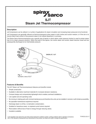
- 1. Description Jet Compressors can be utilized in a number of applications for steam circulation and increasing lower pressures to be functional. Jet Compressors are generally referred as thermocompressors when steam is both motive and suction medium, or if the aim is to recover latent heat content of low pressure steam to be utilized elsewhere in a process. The Spirax Sarco thermocompressors are a specific type of ejector in which steam under pressure (motive) is used to entrain steam that is at a lower pressure (suction). Within the body of the ejector, the motive steam and suction steam become mixed and are subsequently discharged at an intermediate pressure. Features & Benefits The SJT Steam Jet Thermocompressors features and benefits include: • Simple construction • Available in alternative machined materials for increased abrasion resistance. • Compact design and comparatively lightweight which enables overhead installations. • Low capital cost and operating costs. • No moving or rotating parts with minimal maintenance and therefore the units can be installed in remote or with limited accessibility. • No specialist maintenance experience required. • Discharge steam is oil free, no lubrication contamination. • Suitable for hazardous areas, no explosion proof motors required. • Recirculation without loss of heat or energy through reducing valves. • Insulation available. DN200 (8") SJT SJT Steam Jet Thermocompressor Fig. 1 Isometric view of SJT Local regulation may restrict the use of this product below the conditions quoted. Limiting conditions refer to standard connections only. In the interests of development and improvement of the product, we reserve the right to change the specification. TI-P493-02-US 6.17
- 2. SJT Construction and Operation SJT’s typically include the following main design features:- • Body • Nozzle • Diffuser • Spindle • Actuator to move spindle (option for variable type SJT) SJTs can be supplied in alternative materials to suit various application conditions. High pressure motive steam enters the SJT Steam Jet Thermocompressor and passes through the nozzle where the high pressure steam energy is converted into kinetic energy. On leaving the nozzle at high velocity, the steam enters the suction chamber where it is brought in contact with the suction steam. There is then an exchange of momentum between the motive and suction steam, resulting in an acceleration of the suction steam, giving rise to their subsequent entrainment. A uniform mixture results at the narrowest part of the diffuser (called the throat) and finally the reconversion of the velocity energy into pressure energy occurs in the diverging section of the diffuser. Types of Thermocompressor Fixed nozzle type This type of compressor has no regulating spindle. An element of control is achievable by throttling the motive steam pressure via a separate valve upstream of the SJT (See Fig. 3). Typically the fixed nozzle is used when operating loads are stable. Fig. 3 Cross section of fixed nozzel type SJT Fixed Orifice (loads stable, less than 10% variation) Variable Area This compressor includes a motive steam regulating spindle to vary the cross sectional area of the motive steam nozzle (See Fig. 4). It varies the area through which the steam is flowing. This approach maximizes the energy per lb of motive steam that is available at the nozzle to do the work. Typically the variable area SJT is used when either; motive, or suction, or discharge steam varies in condition, and the specific flow or pressure of the discharge is required. Fig. 4 Cross section of variable area SJT Variable Area (Loads/Conditions vary) GASKET BODY NOZZLE DIFFUSER NAME-PLATE Fig. 2 Labeled cross section of SJT Spirax Sarco, Inc., 1150 Northpoint Blvd, Blythewood, SC 29016 Telephone: (803) 714-2000 FAX (803) 714-2222 TI-P493-02-US 6.17
- 3. Performance - Critical or Noncritical Thermocompressors can be categorized as either critical or noncritical based on the compression ratio. In order to determine what type of design the SJT will be, the following compression calculation is completed; If the steam velocity in the diffuser throat is sonic, the design is defined as critical. Sonic velocity exists when the compression ratio (discharge pressure/suction pressure) is equal to or greater than 1.8 to 1. The ratio value changes as a function of the ratio of the specific heat of the motive and suction steam. Unless motive pressure and discharge pressure are decreased proportionally with a critical design, a reduction in motive steam pressure will result in a sudden increase to suction pressure. The relationship between motive pressure and discharge pressure depends on the specific characteristics of the individual design. Sonic designs Subsonic designs Compression ratio (K) greater than 1.8 Compression ratio (K) is less than 1.8 Compression ratio (K) greater than 1.8 With a subsonic design, the motive (HP) steam flowrate can be varied to 'save' steam when process conditions become more favorable. The Suction (LP) steam flowrate can operate with full turndown (100% to 0%) The Suction (LP) steam flowrate can operate with full turndown (100% to 0%). Spirax Sarco offer a special design called a 'Variable Orifice' thermocompressor which has integrated motive steam control. Control options The schematic below illustrates every possible control option that could be used to control an SJT Steam Jet Thermocompressor. Subsonic designs: Option 1 Can be used to control the motive (HP) steam flow from 100% to 80% Option 2 Can be used to control the motive (HP) steam flow from 100% to 35% Option 3 Can be used to bypass additional steam to the discharge. Options 4 or 5 or 6 are occasionally used to maintain the suction (LP) pressure Sonic designs: Option 3 Can be used to bypass additional steam to the discharge Option 4 or 5 Are occasionally used instead of option 6 Option 6 Is usually used to maintain the Suction (LP) pressure (if required) Compression ratio (K) = Discharge pressure (Pd) Suction pressure (Ps) Is K > 1.8 Sonic design Subsonic design For Example: • The discharge pressure = 36.3 psig (2.5 bar g) = 51.0 psi a (3.513 bar a) • The suction pressure = 17.4 psig (1.2 bar g) = 32.1 psi a (2.213 bar a) • The compression ratio (K) = 51.0 psig (3.513 bar g)/32.1 psig (2.213 barg) = 1.59 motive Suction Discharge 1 3 5 6 4 Note: You cannot choose Options 1 or 2 if the SJT Steam Jet Thermocompressor is 'Sonic' Most applications will only use one of the options. Some applications do not require any control. An SJT Steam Jet Thermocompressor will always balance itself to the system pressures. Fig. 5 Control options for SJT Spirax Sarco, Inc., 1150 Northpoint Blvd, Blythewood, SC 29016 Telephone: (803) 714-2000 FAX (803) 714-2222 TI-P493-02-US 6.17
- 4. Variable orifice SJT Steam Jet Thermocompressors Spirax Sarco offers several types of Thermocompressor. The first is the fixed nozzle type where control is achievable by throttling the motive steam pressure via a separate valve upstream of the SJT Steam Jet Thermocompressor (See Control Option 1, previous page, for subsonic units). The other type relies on a motive steam regulating spindle to vary the cross sectional area of the motive steam nozzle (Control Option 2, previous page). Unlike a throttling valve positioned upstream, the regulating spindle does not reduce the motive steam pressure, it simply varies the area through which the steam is flowing, maximizing the utilization of energy in the motive steam. SJT Steam Jet Thermocompressors utilizing a motive steam regulating spindle are often referred to as Variable Orifice Ejectors. The spindle is operated automatically. Selection Variable orifice SJT Steam Jet Thermocompressors should be specified in cases where the suction load, suction pressure or discharge pressure are continually varying, and it is necessary to control one or more of these process parameters as quickly as possible. For cases which involve large variations in load, it is sometimes more cost effective to use several various sized units connected in parallel, than to have one large controlled unit. It may also be necessary to install a bypass valve in some applications. Defining the parameters to be controlled (E.g. pressure, flow, etc.) Will determine the optimum solution for the application, and best return on investment. Spirax Sarco can provide assistance in selecting the right solution for your needs. Typical Applications The following lists the applications where SJT Steam Jet Thermocompressors can be installed, typically for circulating and boosting low pressure steam which would normally go to waste: Applications Industries Drum dryers Paper and Board Industries Flash evaporators Desalination Condensate receivers Chemical, Petro-chemical, Oil and Power Generation Vulcanisers Rubber Industry Single and Multi-stage effect evaporators Food, Dairy, Pharmaceutical & Chemical Industries Wort vessels Brewing Industry Exhaust steam lines Most Process Industries Blanching machines Food Industry How to order Please use the following format to specify a Thermocompressor and include a datasheet detailing all values. Example: 1 off Spirax Sarco Size 6 SJT150CS Steam Jet Thermocompressor having ASME 300 RF slip on flange connections. Note: Attach the SJT Datasheet to the order. Spirax Sarco, Inc., 1150 Northpoint Blvd, Blythewood, SC 29016 Telephone: (803) 714-2000 FAX (803) 714-2222 TI-P493-02-US 6.17
- 5. Datasheet generated by the online software program A typical example is illustrated below: Spirax Sarco SJT Steam Jet Thermocompressor Datasheet 1 Client: Spirax-Sarco Inc. Client Project Ref: 2 Client's Ref: Plant Location: 3 Spirax Ref: SJT Example/SJT00824 Name-plate Tag No. 4 Description: Size 6 Steam Jet Thermocompressor No. OFF: 1 5 Unit Ref: SJT150CS4F0 Operation: 6 Drawing No: DE-SJT00824-1 Serial No: 7 Unit Body Size: 6 8 MOTIVE CONDITIONS MATERIALS OF CONSTRUCTION 9 Pressure (psig) 293.92 Main body Carbon Steel 10 Temperature (°F) 419.0 Nozzle Stainless Steel 11 Flowrate (lb/hr) 5689 Diffuser Carbon Steel 12 Flanges Carbon Steel 13 SUCTION CONDITIONS Gaskets Spirax Sarco to select 14 Pressure (psig) 1.47 Bolts Carbon Steel (if applicable) 15 Temperature (°F) 216.9 Name-plate Stainless Steel 16 Flowrate (lb/hr) 3308 17 MECHANICAL DESIGN Motive Suction/Discharge 18 DISCHARGE CONDITIONS Side Side 19 Pressure (psig) 22.04 Max Design Pressure 22.04 22.04 (psig) 20 Temperature (°F) 294.1 Max Design Temp 428 428 (°F) 21 Flowrate (lb/hr) 8996 Internal Corrosion Allowance 38.1 38.1 (in) 22 DIFFUSER IS SONIC Mechanical Design Code ASME B31.3 23 Welding Standard ASME IX 24 External Surface Finish High Temp Silicone Aluminum 25 Weight TBC (lb) 26 27 DIMENSIONS CONNECTIONS DETAILS Size Rating 28 A - 9.65 in Motive Steam (A) 2 ½ 300 lb 29 B - 11.42 in Suction Steam (B) 6 300 lb 30 C - 54.13 in Discharge Steam (C) 6 300 lb 31 D - 65.55 in Flange Type ASME B 16.5 Slip-On 32 GA DRAWING NOTE: Confirmed dimensions to be issued shortly after order placement 33 34 35 36 37 38 39 40 41 42 43 D A GASKET BODY NOZZLE DIFFUSER NAME-PLATE C B Spirax Sarco, Inc., 1150 Northpoint Blvd, Blythewood, SC 29016 Telephone: (803) 714-2000 FAX (803) 714-2222 TI-P493-02-US 6.17