Downloaded 19 times
![20
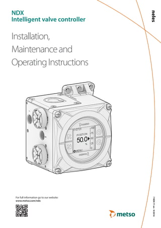
NDX VALVE CONTROLLER
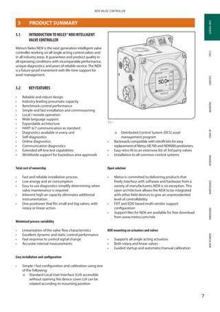
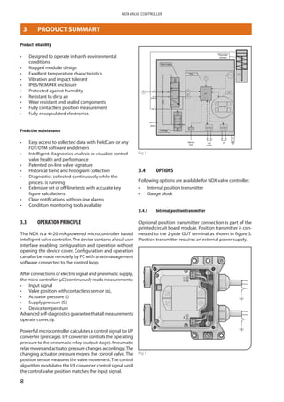
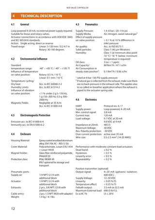
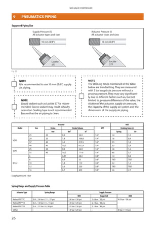
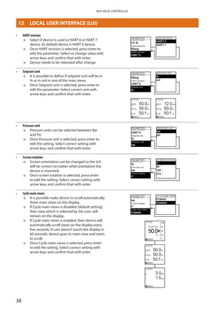
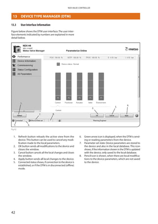
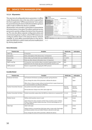
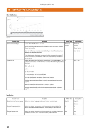
7.3 Installation to any linear actuator
NDX can be easily installed to any linear actuator when the
following installation rules are followed. In order to guar
antee the best possible position measurement accuracy,
NDX and position feedback magnet must be positioned
according to the following guidelines.
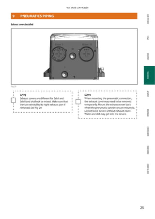
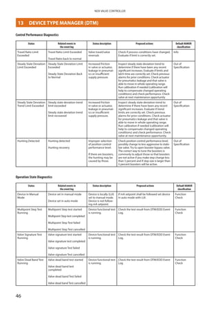
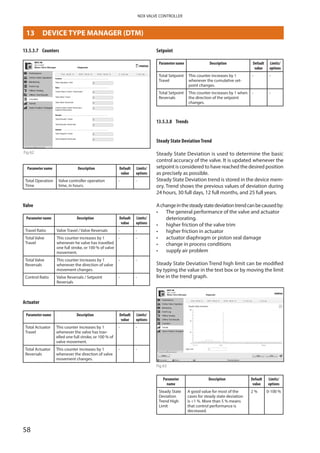
Tolerance +/- 3 [mm]
Magnet center
Magnet center travel limit
(fixing bolt line)
Magnet center travel limit
(fixing bolt line)
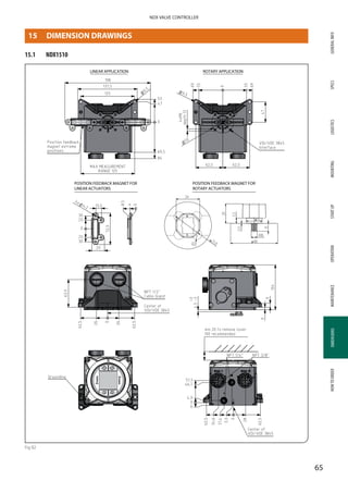
Fig 20
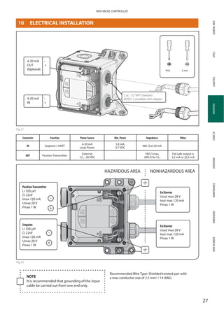
When installing the device to any other actuator model
make sure that the following tolerances are followed with
magnet mounting.
1. Magnet shall be centered within +/- 3 mm tolerance
as shown in the picture.
2. Magnet center shall never exceed the magnet center
travel limits shown in the picture.
NOTE
Use only Metso original magnets.
Bracket and fixing bolt material should have
low magnetic permeability (e.g. AISI316 or
aluminium).
NOTE
Always ensure that the magnet center stays
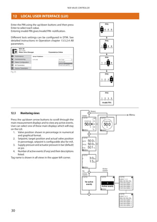
within magnet center travel limits on the
complete operation range of the valve.
NOTE
Shorter actuator stroke allows more freedom
for alignment of the magnet and NDX in
actuator stroke direction. Magnet position does
not affect the measurement accuracy as long
as the magnet center stays within the magnet
center travel limits for whole travel range.
MOUNTING
7 LINEAR MOUNTING](https://image.slidesharecdn.com/neles-ndx-intelligent-valve-positioner-mead-obrien-170129160719/85/Neles-NDX-Intelligent-Valve-Positioner-20-320.jpg)
![GENERALINFOSPECSMOUNTINGSTARTUPOPERATIONMAINTENANCEDIMENSIONSHOWTOORDERLOGISTICS
21
NDX VALVE CONTROLLER
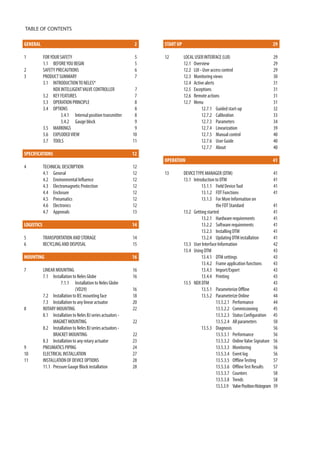
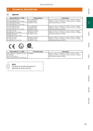
MOUNTING
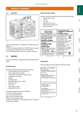
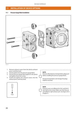
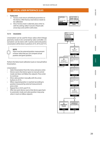
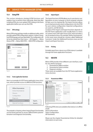
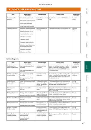
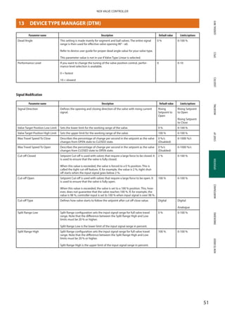
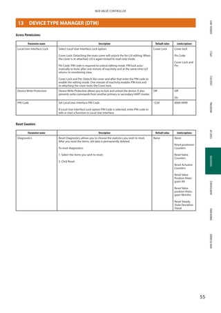
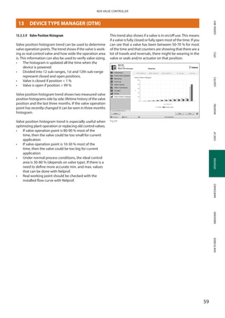
3. The distance between the magnet and the device
bottom shall be 4.5 mm with +/- 3 mm tolerance
(1.5 - 7.5 mm).
4. Check that following magnet alignment require
ments are not exceeded.
Figure 23 shows the exclusion zone. There is no material
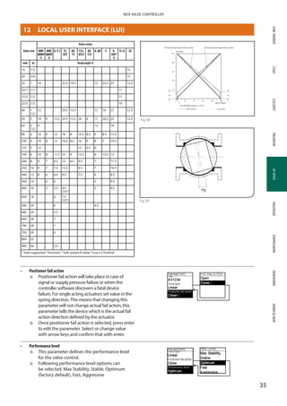
limitation outside the exclusion zone, but to guarantee the
optimal performance do not use any magnetic material
inside the zone. Inside the exclusion zone but close to the
”walls”AISI 304 and any austenitic steel can be used.
Fig 23
4.5 +/- 3 [mm]
Fig 21
Max 6 deg
Max 1 mm
Max 3 mm
Max 4 deg Max 3 deg
Max 2 mm
Fig 22
7 LINEAR MOUNTING](https://image.slidesharecdn.com/neles-ndx-intelligent-valve-positioner-mead-obrien-170129160719/85/Neles-NDX-Intelligent-Valve-Positioner-21-320.jpg)

The document provides installation, maintenance, and operation instructions for the Neles® NDX intelligent valve controller, detailing its features, safety precautions, and technical specifications. It emphasizes the controller's robust design, easy integration with various actuators, and advanced diagnostics capabilities. Additionally, it includes guidelines for setup, configuration, troubleshooting, and maintenance, ensuring safe and efficient use in various industrial applications.


![Shaft Alignment Trainer [SAT] presentation](https://cdn.slidesharecdn.com/ss_thumbnails/satpresentation-130805143252-phpapp01-thumbnail.jpg?width=640&height=640&fit=bounds)