SlideShare a Scribd company logo
1 of 104
Slayt No: 1/120Mustafa Münir ATAGÜN DRILLING FLUID ENGINEERING
Drilling Fluid Engineering MMA
1- DRILLING FLUID SELECTION …………………………………… 2
2- SOLID CONTROL IN DRILLING FLUIDS……………………… 9
3- SUBSURFACE PRESSURES……………………………………….32
4- HYDRAULIC OF DRILLING FLUIDS………………………. …..49
4- OIL BASE DRILLING FLUID………………………………………. 66
5-CLAYS AND CLAYS CHEMISTRY………………………………… 80
6- MUD PROGRAMS, RECAPS…………………………………….. 98
Slayt No: 2/120Mustafa Münir ATAGÜN DRILLING FLUID ENGINEERING
Drilling Fluid Engineering
DRILLING FLUID SELECTION:
Drilling fluid selection for a particular well starts with a full
consideration of all the factors mentioned below.. The study should
include examining well records from nearby wells, looking at the type
of drilling fluid used, and any fluid related problems which might have
been experienced. This could range from slow ROP’s to Hole Stability
issues, to Reservoir Damage.
It is not subject within the scope of this section go deeply into
the drilling fluid selection factors. The intention is to introduce to you
with the factors for selection the Drilling Fluids.
MMA
Slayt No: 3/120Mustafa Münir ATAGÜN DRILLING FLUID ENGINEERING
DRILLING FLUID SELECTION
1- ABNORMAL PRESSURES: To prevent the rock from failing mechanically at
the borehole (sloughing or caving), and to prevent fluids within permeable zones from
flowing into the borehole, a sufficient pressure must be maintained by the drilling fluid
to at least balance the fluid, or pore, pressure within the rock. Balancing the physical
stresses that effect wellbore stability then, are simply a matter of adjusting the Mud
Weight.
2- ACTIVE CLAYS: It is impossible to prevent hydration of shale formation
when using a water based drilling fluid. This is because, while Osmotic Forces may be
overcome by adding salt to the mud, there is no way to counter the Clay Mineral
Hydration force, when drilling with a water based fluid. Further, water may be sucked
into the formation from Invert Emulsion Oil and Synthetic base muds, if an inadequate
water phase salinity is run. As a general rule, deeper, hotter and older shale is less
chemically reactive than younger, shallower and cooler clay sediment. It should be
obvious that these factors need to be taken into consideration when planning a Drilling
Fluid Program, particularly if planning to use a water base mud.
3- HIGH TEMPERATURES: From the drilling fluid point of view high temperatures can
be considered as those above which conventional drilling fluid additives begin to thermally
degrade at an appreciable rate. The degradation leads to loss of product function, and system
maintenance becomes difficult and expensive.
MMA
Slayt No: 4/120Mustafa Münir ATAGÜN DRILLING FLUID ENGINEERING
DRILLING FLUID SELECTION
4- DRILLING AND CLEANING THE HOLE: The choice of Drilling Fluid
will effect the potential Rate of Penetration. Drilling Fluid Properties are also
critical to Hole Cleaning. It is useful to have an understanding of the
mechanisms involved both in selecting and designing the Fluid for a specific
well, and in getting the most out of the Fluid being used.
5- RATE OF PENETRATION: The choice of Drilling Fluid will effect the
potential Rate of Penetration. Drilling Fluid Properties are also critical to Hole
Cleaning. It is useful to have an understanding of the mechanisms involved
both in selecting and designing the Fluid for a specific well, and in getting the
most out of the Fluid being used. This relationship varies considerably
between conventional roller cone bits, and the more modern PDC drag bits.
6- CUTTINGS TRANSPORT / HOLE CLEANING : The transportation of
the cuttings from bit to surface has always been one of the main functions of
drilling fluids. The relationship of mud rheology to cuttings transport in
vertical holes has been understood for a long time. In deviated holes
however, other factors aside from the “carrying capacity” of the mud come
into play. Cutting properties is also effect the hole cleaning and ROP related
with the mud selection.
MMA
Slayt No: 5/120Mustafa Münir ATAGÜN DRILLING FLUID ENGINEERING
DRILLING FLUID SELECTION
7- CUTTINGS PROPERTIES: Researchers who experimented with
different density cuttings found that the greater the density, the greater
the tendency to settle out, and the harder to remove. The density and
other properties of the cuttings affect the cleaning of the well. While mud
selection it must be considered.
8- HYDRAULİC: Hydraulics is defined as “the physical science and
technology of the static and dynamic behavior of fluids”. In this section we
are concerned with pumping Drilling Fluids from the mud tanks, through
surface lines and hoses, down the drill string, and circulating it back up the
annulus. A certain increment of pressure is required to move the mud
through each section of the circulating system.
The pressure required to circulate a fluid through a particular
section of pipe or hose, depends on cross sectional area and length of the
tubular section, the physical properties of density and rheology of the
fluid, and the flow rate. In a Drilling Fluid, the Rheology defines the flow
properties of that fluid.
MMA
Slayt No: 6/120Mustafa Münir ATAGÜN DRILLING FLUID ENGINEERING
DRILLING FLUID SELECTION
9- FORMATION DAMAGE:: As a drill bit cuts a permeable zone,
and fresh virgin rock is exposed to the drilling fluid, there is initially a
spurt of whole mud into the pores of the rock. If the particle size
distribution of the solids in the mud is good, mud solids will almost
instantly bridge the pore throats. Whole mud will not penetrate more
than a few millimeters at most into the rock, and a filter cake will
quickly be formed, restricting the flow of filtrate into the formation.
10- CORROSION: Acid conditions promote corrosion. CO2 gas
and the action of bacteria on some mud products produce acids, or
corrosive byproducts. Increasing pH reduces corrosion and bacterial
action, and reacts out CO2, but is not always viable when drilling
reactive formations. Techniques for minimizing corrosion include
raising pH, using oxygen scavengers, and adding amine type products
to the fluid to coat steel components and reduce reactivity.
MMA
Slayt No: 7/120Mustafa Münir ATAGÜN DRILLING FLUID ENGINEERING
DRILLING FLUID SELECTION
11- LUBRICITY: Lubricity is generally not a problem with oil or
Synthetic base muds. High torque can be a problem in some water based
drilling fluids, mainly those with a low solids content. Solid particles within
drilling fluids are the main source of lubricating properties. Emulsified fluids
act as finely divided particles and have the same effect. Diesel oil added to
water base mud has an initial lubricating effect, not from the properties of the
oil, but as a particle within the fluid
12- GAS HYDRATE: Gas hydrates are solid mixtures of gas and water,
which react to form a rigid lattice type structure. They form, usually at the
seabed, due to a combination of high hydrostatic pressures, and low seabed
temperatures. High fluid velocities, and pressure pulses may also contribute
to hydrate formation. They may form above the freezing temperature of
water. Oil and Synthetic base muds, which have high CaCl2 water phase
salinities will not exhibit hydrate formation problems. Hydrates can however
form in these muds if the water phase salinity is too low. This should not be a
problem in any Unocal operation.
MMA
Slayt No: 8/120Mustafa Münir ATAGÜN DRILLING FLUID ENGINEERING
DRILLING FLUID SELECTION MMA
Slayt No: 9/120Mustafa Münir ATAGÜN DRILLING FLUID ENGINEERING
SOLID CONTROL IN DRILLING FLUIDS
Introduction
Laboratory tests and practical field experience show that closely monitoring
drilled solids in the mud and minimizing their concentration can result in large
savings of both money and time. These savings manifest in three ways:
Improved drilling rate
Increased bit life
Reduced wear on mud pumps.
MMA
Solids control methods are based on the average diameters of the particles being
handled:
Coarse Particles: Greater than 2000 microns
Intermediate Particles: From 250 and 2000 microns
Medium Particles: from 75 to 249 microns
Fine Particles: from 45 to 74 microns
Ultra-fine Particles: from 2 to 44 microns
Collodial Particles: less than 2 microns
Slayt No: 10/120Mustafa Münir ATAGÜN DRILLING FLUID ENGINEERING
SOLID CONTROL IN DRILLING FLUIDS MMA
Slayt No: 11/120Mustafa Münir ATAGÜN DRILLING FLUID ENGINEERING
SOLID CONTROL IN DRILLING FLUIDS MMA
Slayt No: 12/120Mustafa Münir ATAGÜN DRILLING FLUID ENGINEERING
SOLID CONTROL IN DRILLING FLUIDS
SETTLING: Treatment of solids-related mud problems may involve
one or more of the following mechanisms: settling, dilution, mechanical
separation and chemical treatment.
Settling involves retaining mud in a nearly quiescent state long
enough to allow the undissolved solids, which are heavier than water, to "fall
out" of the fluid. The relative success of this method depends on several
factors, including the size and shape of the particles, the density of the
particles, the density of the fluid, and the overall retention (settling) time.
The settling time can be reduced by using a flocculant to increase the particle
size, or by inducing centrifugal force to increase the gravitational effect.
MMA
Slayt No: 13/120Mustafa Münir ATAGÜN DRILLING FLUID ENGINEERING
SOLID CONTROL IN DRILLING FLUIDS
Dilution, unlike the other solids control methods, does not involve removing solid
particles from the mud; rather, it is a means of decreasing the solids concentration by
adding base fluid to the system. Dilution is most often used to correct mud properties that
have been altered by the accumulation of drilled solids. The drawback to this method is that
as drilling progresses, concentrations of drilled solids continue to increase, and undesirable
mud properties eventually reappear. Also, dilution is often expensive for the following
reasons:
The consumption of the products required to maintain desired mud properties is
continually increasing.
Lack of storage space for the increased mud volume often leads to the discarding of
hundreds of barrels of valuable drilling mud.
Extra cleanup and transportation costs are incurred in environmentally sensitive areas.
MMA
Slayt No: 14/120Mustafa Münir ATAGÜN DRILLING FLUID ENGINEERING
SOLID CONTROL IN DRILLING FLUIDS
Mechanical separation devices are available in two basic types:
vibrating screening devices (shakers) and systems that use centrifugal force to
increase settling rate. Mechanical treatment of solids buildup is often the
most practical and cost effective of the four available methods—it does not
alter essential mud properties and it decreases the need for dilution.
Generally speaking, the greater the cost per barrel of a given mud, the greater
the savings in using mechanical equipment to rectify mud properties.
The equipment used to mechanically remove solids from the mud must be
designed to fit the requirements of a given drilling operation; not every piece
of equipment is appropriate in every situation. Furthermore, the equipment
specifically selected to aid in mechanical removal of solids must be rigged up
and maintained to ensure that the units operate at peak performance.
MMA
Slayt No: 15/120Mustafa Münir ATAGÜN DRILLING FLUID ENGINEERING
SOLID CONTROL IN DRILLING FLUIDS
Shale Shakers: The
double-decker shale shaker has
two screens mounted on a flat-
bed construction. The screens
can range down to 100 mesh
with the mesh cross section
varying from square to an
exaggerated rectangle. Drilled
solids down to 177 microns are
removed by 80-mesh screens,
and 840-micron size particles by
20-mesh screens.
MMA
Slayt No: 16/120Mustafa Münir ATAGÜN DRILLING FLUID ENGINEERING
SOLID CONTROL IN DRILLING FLUIDS
Desilters and Desanders: The desilters/desanders must be equipped with centrifugal
pumps capable of providing sufficient pressure to the hydrocyclones to allow them to operate in
the desired pressure range. When correctly installed and operating in the design range, desilters
and desanders are capable of removing up to 95% of solid particles larger than 15 microns.
MMA
Slayt No: 17/120Mustafa Münir ATAGÜN DRILLING FLUID ENGINEERING
SOLID CONTROL IN DRILLING FLUIDS
Centrifuge: In weighted mud systems it is often desirable to reduce mud maintenance
costs by methods other than dilution. Since it is not practical to use desilting equipment in these
systems, a centrifuge is often used.
Mud centrifuges work on the decanting principle. The mud flow enters a chamber
rotating at a high speed, and centrifugal force separates the mud stream into three components:
fluid phase, low-specific-gravity solids, and high-specific-gravity solids. Following separation of the
low-gravity solids, the high-gravity solids are returned to the active mud system.
In unweighted mud systems, a high-volume decanting centrifuge removes low-specific-
gravity drilled solids most efficiently and economically. The centrifuge can be operated on
unweighted muds at speeds up to 2200 to 2400 rpm, creating centrifugal forces greater than 1500
G-force. The high-volume centrifuge can remove fine solids down to two microns (e.g., bentonite
and clays) .
The separation efficiency of hydrocyclones depends on four general factors:
1. Fluid properties;
2. Particle properties;
3. Flow parameters;
4. Hydrocyclone parameters.
MMA
Slayt No: 18/120Mustafa Münir ATAGÜN DRILLING FLUID ENGINEERING
Slayt No: 19/120Mustafa Münir ATAGÜN DRILLING FLUID ENGINEERING
SOLID CONTROL IN DRILLING FLUIDS MMA
Slayt No: 20/120Mustafa Münir ATAGÜN DRILLING FLUID ENGINEERING
SOLID CONTROL IN DRILLING FLUIDS MMA
Slayt No: 21/120Mustafa Münir ATAGÜN DRILLING FLUID ENGINEERING
Barium sulfate (barite) is the primary additive used to increase the density of
clay/water muds. Densities ranging from 9 – 19 lbm/gal can be obtained using mixtures of barium
sulfate, clay, and water. The specific gravity of pure barium fulfate is 4.5, but the commercial grade
used in drilling fluids (API barite) has an average specific gravity of about 4.2.
Recently, alternative density control agents such as hematite (Fe2O3) with specific
gravity ranging from 4.9 to 5.3 and ilmenite (FeO.TiO2), with specific gravity ranging from 4.5 to 5.1
have been introduced. Because of their hardness, there is a concern about the abrasive of these
materials in the circulating system.
SOLID CONTROL IN DRILLING FLUIDS
Density control
MMA
Slayt No: 22/120Mustafa Münir ATAGÜN DRILLING FLUID ENGINEERING
SOLID CONTROL IN DRILLING FLUIDS
The mixture density is given by
If the storage capacity is available, to increase the density of the drilling fluid, we simply add barite to the mud.
Therefore, the known and unknown variables in this case are:
Known: V1, r1, rB, r2 Unknown: V2, mB
MMA
r1, V1
r2, V2
rB, VB
Slayt No: 23/120Mustafa Münir ATAGÜN DRILLING FLUID ENGINEERING
SOLID CONTROL IN DRILLING FLUIDS
For ideal mixing the volume of mud, V1 and
weight material, VB, must sum to the desired new volume, V2
Likewise, the total mass of mud and weight material must sum
to the desired density-volume product
Solving these equations simultaneously for unknowns V2 and
mB yields
MMA
Slayt No: 24/120Mustafa Münir ATAGÜN DRILLING FLUID ENGINEERING
SOLID CONTROL IN DRILLING FLUIDS
The addition of large amounts of API barite to the drilling fluid can cause the
drilling fluid to become quite viscous. The finely divided API barite has an extremely large
surface area and can absorb a significant amount of free water in the drilling fluid. This
problem can be overcome by adding water with the weight material to make up for the
water adsorbed on the surface of the finely divided particles. It is often desirable to add only
the minimum water required to wet the surface of the weight material. The addition of
approximately 1 gallon of water per 100 lbm of API barite is usually sufficient to prevent an
unacceptable increase in fluid viscosity.
Mass balance
MMA
Slayt No: 25/120Mustafa Münir ATAGÜN DRILLING FLUID ENGINEERING
SOLID CONTROL IN DRILLING FLUIDS
Solving these equations for unknowns V1 and mB gives
Note that VwB is the volume of water need to add with one pound of barite. VwB = 0.01
For mB pounds of barite, VwB = 0.01 mB.
MMA
Slayt No: 26/120Mustafa Münir ATAGÜN DRILLING FLUID ENGINEERING
SOLID CONTROL IN DRILLING FLUIDS MMA
Slayt No: 27/120Mustafa Münir ATAGÜN DRILLING FLUID ENGINEERING
SOLID CONTROL IN DRILLING FLUIDS MMA
Example-1: is desired to increase the density of 200 bbl of 11-lbm/gal mud to
11.5 lbm/gal using API barite. The final volume is not limited. Compute the weight of
API barite required.
Solution:
The final volume is given
The weight barite required
For a final volume of 800 bbl. V1 is given
Thus, 99.47 bbl of mud should be discarded before adding any API barite. The mass of
API barite needed is given by
The volume of water to be added with the barite
0.01mB = 1,083 gal or 25.79 bbl.
Slayt No: 28/120Mustafa Münir ATAGÜN DRILLING FLUID ENGINEERING
SOLID CONTROL IN DRILLING FLUIDS MMA
Slayt No: 29/120Mustafa Münir ATAGÜN DRILLING FLUID ENGINEERING
SOLID CONTROL IN DRILLING FLUIDS
Poor Boy Degasser
MMA
Slayt No: 30/120Mustafa Münir ATAGÜN DRILLING FLUID ENGINEERING
SOLID CONTROL IN DRILLING FLUIDS
Vacum Type Degasser
MMA
Slayt No: 31/120Mustafa Münir ATAGÜN DRILLING FLUID ENGINEERING
SOLID CONTROL IN DRILLING FLUIDS
Three Phase Degasser
MMA
Slayt No: 32/120Mustafa Münir ATAGÜN DRILLING FLUID ENGINEERING
Subsurface Pressures
Pressure
MMA
Stress/pressure What is the difference?
•Pressure - Scalar quantity •Stress - Tensor quantity
•Pressure – in fluids •Stress – in solid bodies
Slayt No: 33/120Mustafa Münir ATAGÜN DRILLING FLUID ENGINEERING
Subsurface Pressures
Hydrostatic Pressure
MMA
Slayt No: 34/120Mustafa Münir ATAGÜN DRILLING FLUID ENGINEERING
Subsurface Pressures
Hydrostatic Pressure In Drilling Wells
MMA
Slayt No: 35/120Mustafa Münir ATAGÜN DRILLING FLUID ENGINEERING
Subsurface Pressures MMA
Drilling a hole through a rock formation interrupts the pattern of stresses
present within the rock. These stresses have both horizontal and vertical components,
and are generally present due to the vertical loading, or overburden load, upon a given
point within the rock.
During a period of erosion and sedimentation, grains of sediment are
continuously building up on top of each other, generally in a water filled environment.
As the thickness of the layer of sediment increases, the grains of the sediment are
packed closer together, and some of the water is expelled from the pore spaces.
However, if the pore throats through the sediment are interconnecting all the way to
surface the pressure of the fluid at any depth in the sediment will be same as that
which would be found in a simple colom of fluid. This pressure is called NORMAL
PRESSURE and only dependents on the density of the fluid in the pore space and the
depth of the pressure measurement (equal to the height of the colom of liquid). it will
be independent of the pore size or pore throat geometry.
Normal Pressure
Slayt No: 36/120Mustafa Münir ATAGÜN DRILLING FLUID ENGINEERING
Subsurface Pressures MMA
The vertical pressure at any point in the earth is known as the overburden
pressure or geostatic pressure. The overburden pressure at any point is a function of
the mass of rock and fluid above the point of interest. In order to calculate the
overburden pressure at any point, the average density of the material (rock and
fluids) above the point of interest must be determined. The average density of the
rock and fluid in the pore space is known as the bulk density of the rock
Overburden Pressure
Slayt No: 37/120Mustafa Münir ATAGÜN DRILLING FLUID ENGINEERING
Subsurface Pressures MMA
Slayt No: 38/120Mustafa Münir ATAGÜN DRILLING FLUID ENGINEERING
Subsurface Pressures
Normal Pressure
MMA
The altitude which is generally used during drilling operations is the drill
floor elevation but a more general altitude, used almost universally, is Mean Sea
Level, MSL. When the pore throats through the sediment are interconnecting, the
pressure of the fluid at any depth in the sediment will be same as that which would
be found in a simple column of fluid and therefore the pore pressure gradient is a
straight line. The gradient of the line is a representation of the density of the fluid.
Hence the density of the fluid in the pore space is often expressed in units of psi/ft.
Slayt No: 39/120Mustafa Münir ATAGÜN DRILLING FLUID ENGINEERING
Subsurface Pressures MMA
Normal Pressure – Overburden Pressure
Slayt No: 40/120Mustafa Münir ATAGÜN DRILLING FLUID ENGINEERING
Subsurface Pressures
Pore pressures which are found to lie above or below the “normal”
pore pressure gradient line are called abnormal pore pressures. These
formation pressures may be either Subnormal (i.e. less than 0.465 psi/ft) or
Overpressured (i.e. greater than 0.465 psi/ft).
Compaction is a slow process of increasing load from above, re-
alignment of clay particles, and gradual expulsion of fluid from the rock, with
resulting decrease in porosity and increase in density. In this process if excess
fluid is trapped in the rock, the formation water may take up more than its
share of the overburden load, and by definition, be abnormally pressured.
The mechanisms which generate these abnormal pore pressures can
be quite complex and vary from region to region. However, the most common
mechanism for generating overpressures is called Undercompaction and can
be best described by the undercompaction model.
MMA
Abnormal Pressure
Slayt No: 41/120Mustafa Münir ATAGÜN DRILLING FLUID ENGINEERING
Subsurface Pressures
Abnormal Pressure
MMA
The weight material barite required
Slayt No: 42/120Mustafa Münir ATAGÜN DRILLING FLUID ENGINEERING
Subsurface Pressures MMA
(a) Formation Foreshortening
During a compression process there is some bending of strata. The upper beds can
bend upwards, while the lower beds can bend downwards. The intermediate beds must
expand to fill the void and so create a subnormally pressured zone. This is thought to
apply to some subnormal zones in Indonesia and the US. Notice that this may also
cause overpressures in the top and bottom beds.
Subnormal Formation Pressure
Causes of Subnormal Pressure
Slayt No: 43/120Mustafa Münir ATAGÜN DRILLING FLUID ENGINEERING
Subsurface Pressures MMA
(b) Thermal Expansion: As sediments and pore fluids are buried the temperature
rises. If the fluid is allowed to expand the density will decrease, and the pressure will
reduce.
(c) Depletion: When hydrocarbons or water are produced from a competent
formation in which no subsidence occurs a subnormally pressured zone may result.
This will be important when drilling development wells through a reservoir which has
already been producing for some time. Some pressure gradients in Texas aquifers
have been as low as 0.36 psi/ft
Subnormal Formation Pressure
Slayt No: 44/120Mustafa Münir ATAGÜN DRILLING FLUID ENGINEERING
(d) Potentiometric Surface: This mechanism refers to the structural relief of a
formation and can result in both subnormal and overpressured zones. The potentiometric surface is
defined by the eight to which confined water will rise in wells drilled into the same aquifer. The
potentiometric surface can therefore be thousands of feet above or below ground level
MMASubsurface Pressures
Slayt No: 45/120Mustafa Münir ATAGÜN DRILLING FLUID ENGINEERING
(a) Incomplete sediment compaction or undercompaction:
is the most common mechanism causing overpressures. In the rapid burial of low permeability
clays or shales there is little time for fluids to escape. The formation pressure will build up and
becomes overpressured formtion. In other words, If the burial is rapid and the sand is enclosed
by impermeable barriers, there is no time for this process to take place, and the trapped fluid
will help to support the overburden.
(b) Faulting
Faults may redistribute sediments, and place permeable zones opposite impermeable zones,
thus creating barriers to fluid movement. This may prevent water being expelled from a shale,
which will cause high porosity and pressure within that shale under compaction.
(c) Massive Rock Salt Deposition
Deposition of salt can occur over wide areas. Since salt is impermeable to fluids, the underlying
formations become overpressured. Abnormal pressures are frequently found in zones directly
below a salt layer.
Subsurface Pressures MMA
Causes of Abnormal Pressure
Slayt No: 46/120Mustafa Münir ATAGÜN DRILLING FLUID ENGINEERING
Subsurface Pressures MMA
(d) Phase Changes during Compaction: Minerals may change phase under increasing
pressure, e.g. gypsum (CaSO4.H2O) converts to anhydrite plus free water. It has been
estimated that a phase change in gypsum will result in the release of water. The volume of
water released is approximately 40% of the volume of the gypsum. If the water cannot
escape then overpressures will be generated. Conversely, when anhydrite is hydrated at
depth it will yield gypsum and result in a 40% increase in rock volume. The transformation
of montmorillonite to illite also releases large amounts of water.
(e) Repressuring from Deeper Levels: This is caused by the migration of fluid from a
high to a low presssure zone at shallower depth. This may be due to faulting or from a
poor casing/cement job. The unexpectedly high pressure could cause a kick, since no
lithology change would be apparent. High pressures can occur in shallow sands if they are
charged by gas from lower formations.
(f) Generation of Hydrocarbons: Shales which are deposited with a large content of
organic material will produce gas as the organic material degrades under compaction. If it
is not allowed to escape the gas will cause overpressures to develop. The organic by-
products will also form salts which will be precipitated in the pore space, thus helping to
reduce porosity and create a seal.
Slayt No: 47/120Mustafa Münir ATAGÜN DRILLING FLUID ENGINEERING
Subsurface Pressures MMA
When two aqueous fluids as shown below having different salinities are
exposed to each other, there is a tendency for the less salty fluid to dilute the
more salty fluid, due to Osmotic Force. When a hole is drilled through a shale, if
the Drilling Fluid contains less salt than the shale, there will be a tendency for
water to migrate into the shale. This will cause swelling and failure of the rock.
Osmotic Pressure
Slayt No: 48/120Mustafa Münir ATAGÜN DRILLING FLUID ENGINEERING
Subsurface Pressures MMA
Fracture pressure is the pressure in the wellbore at which a formation will crack
The stress within a rock can be resolved into three principal stresses. A formation will fracture when
the pressure in the borehole exceeds the least of the stresses within the rock structure. Normally, these fractures
will propagate in a direction perpendicular to the leastss.
At sufficient depths (usually below 1000 m or 3000 ft) the minimum principal stress is horizontal;
therefore, the fracture faces will be vertical. For shallow formations, where the minimum principal stress is
vertical, horizontal (pancake) fractures will be created.
Fracture Pressure
Slayt No: 49/120Mustafa Münir ATAGÜN DRILLING FLUID ENGINEERING
Hydraulics of Drilling Fluids MMA
Mud-Weight Equivalent, also known as Equivalent Mud Weight
(EMW) is the total amount of pressure exerted at a true vertical depth which is
denoted in the mud density. The formation during circulation can hold a specific
mud weight and pressure. This amount of mud weight is referred to as Mud-
Weight Equivalent.
Hydrostatic Pressure of in fluid column
if Po = 0
Hydrostatic Pressure in Fluid Column
0052.0 pDp  r
Dp 052.0 r
D
p
052.0
rThe fluid density
Example: Calculate the static mud density required to prevent flow from a permeable
stratum at 12,200ft if the pore pressure of the formation fluid is 8500psig.
Solution:
The mud density must be at least 13.4 lbm/gal
gallbm
D
p
/4.13
200,12052.0
8500
052.0


r
Slayt No: 50/120Mustafa Münir ATAGÜN DRILLING FLUID ENGINEERING
Hydraulics of Drilling Fluids MMA
Hydrostatic Pressure in Gas Column
Hydrostatic pressure of the column
İdeal gas equation
Finally
dDdp r052.0
TR
M
m
ZTRnZpV 
TZ3.80
pM
ZRT
pM
V
m
r
dD
Mp
dp
TZ80.3
052.0
  
D
D
dD
M
00 TZ1544p
dpp
p
TZ1544
)(
0
0DDM
epp


P0
P0 +
dP
Slayt No: 51/120Mustafa Münir ATAGÜN DRILLING FLUID ENGINEERING
Hydraulics of Drilling Fluids MMA
A well contains tubing filled with methane gas (MW = 16) to a vertical depth of
10000ft. The annular space is filled with a 9.0 lbm/gal brine. Assuming ideal gas behavior,
compute the amount by which the exterior pressure on the tubing exceeds the interior
tubing pressure at 10,000ft if the surface tubing pressure is 1000 psia and the mean gas
temperature is 140F. If the collapse resistance of the tubing is 8330 psi, will the tubing
collapse due to the high external pressure?
The pressure in the annulus (external pressure) at D = 10,000 ft is
P2 = 0.052 * 9.0 * 10,000 + 14.7 = 4,695 psia
The pressure in the tubing (internal pressure) at D = 10,000ft
Pressure difference = p2 – p = 4695 – 1188 = 3507 < 8330 psia
The tubing will withstand the high external pressure
Hydrostatic Pressure in Gas Column
psiae
DDM
epp 11881000
TZ1544
)0(
0
)140460(*1544
10000*16




Slayt No: 52/120Mustafa Münir ATAGÜN DRILLING FLUID ENGINEERING
Hydraulics of Drilling Fluids MMA
The effective density exerted by a circulating fluid against the formation that
takes into account the pressure drop in the annulus above the point being considered.
The ECD is calculated as:
r – mud density, ppg
P – Sum of the hydrostatic pressure and the frictional pressure drop in the annulus between
the depth D and surface, Psig
D – the true vertical depth, ft
Example: A 9.5-PPG drilling fluid is circulated through the drill pipe and the
annulus. The frictional pressure losses gradient in the annulus is 0.15. Calculate the
equivalent circulating density in PPG.
Solution:
r = 9.5 + P/0.052 = 9.5 + 0.15 / 0.052 = 12.4 PPG
Equivalent Circulating Density (ECD)
Slayt No: 53/120Mustafa Münir ATAGÜN DRILLING FLUID ENGINEERING
Hydraulics of Drilling Fluids MMA
Flow Rate
WHERE
v = average velocity, ft/s
q = flow rate, gal/min
d = internal diameter of pipe, in.
d2 = internal diameter of outer pipe or
borehole, in.
d1 =external diameter of inner pipe, in.
2
448.2 d
q
v 
 2
1
2
2448.2 dd
q
v


Annular Flow
Pipe Flow
Flow rate is one of the main factors affecting hole cleaning. More flow rate is not always the way to
improve hole cleaning because might cause erosion or hole washout, therefore enlarging the hole causing
less annular velocity and decreasing cuttings transport.
Below a useful table showing the recommended flow rate for highly deviated and horizontal wells:
Slayt No: 54/120Mustafa Münir ATAGÜN DRILLING FLUID ENGINEERING
Hydraulics of Drilling Fluids MMA
Buoyancy
The behavior of an object submerged in a fluid is governed by Archimedes'
Principle. Archimedes determined that a body which is completely or partially submerged
in a fluid experiences an upward force called the Buoyant Force, B , which is equal in
magnitude to the weight of the fluid displaced by the object. This principle can be used to
explain why ships, loaded with millions of kilograms of cargo, are able to float.







o
l
oe WW
r
r
1
We ,: effective weight,
W: weight of the object in air,
Wbo: Buoyant force.
rl , ro: densities of liquid and the object
Slayt No: 55/120Mustafa Münir ATAGÜN DRILLING FLUID ENGINEERING
Hydraulics of Drilling Fluids MMA
10,000 ft of 19.5-lbm/ft drillpipe and 600 ft of 147 lbm/ft drill collars are
suspended off bottom in a 15-lbm/gal mud. Calculate the effective hook load that
must be supported by the derrick. Density of steel is 65.5 lbm/gal
Solution:
W = 19.5 * 10000 + 147 * 600 = 283200 lbm
We = W(1 - rf/rs) = 283200*(1 - 15/65.5)= 218300 lbm
(density of steel = 65.5 lbm/gal = 490lbm/cu ft) W
Fb
PT
Pb
H
+
Slayt No: 56/120Mustafa Münir ATAGÜN DRILLING FLUID ENGINEERING
Hydraulics of Drilling Fluids
1.48
MMA
Efficient cuttings transport and hole cleaning is a very important factor that must be
considered during drilling operations. In inclined and horizontal drilling, hole cleaning is a
common issue since there is high tendency for formation of cuttings bed in the hole
which can lead to several complex problems. The optimization of cuttings transport
depends on so many factors like hole angle, cutting size, drill string rotation, drill pipe
eccentricity, bit hydraulics ( flow rate, anulus velocity, slip velocity, nozzle velocity, jet
impact force, bit hydraulic horse power) etc.
Here is a rule of thumb for optimization and cleanin the hole for roller cone bits.
Jet Velocity- Jet Impact Force
Slayt No: 57/120Mustafa Münir ATAGÜN DRILLING FLUID ENGINEERING
Hydraulics of Drilling Fluids MMA
Pressure drop across the bit
factorcorrectionC
p
Cv
d
b
dn
10074.8 4



 
r
22
d
2-5
C
10*8.311
t
bit
A
q
Δp
r

ti
i
n
n
n
A
q
A
q
A
q
A
q
A
q
A
q
v 

....
3
3
2
2
1
1
Assuming a constant Pb velocity through all the nozzles
pqcF dj  r01823.0Hydraulic İmpact Force
Slayt No: 58/120Mustafa Münir ATAGÜN DRILLING FLUID ENGINEERING
Hydraulics of Drilling Fluids MMA
Example: A 12.0 lbm/gal drilling fluid is flowing through a bit containing three
13/32 in nozzles at a rate of 400 gal/min. Calculate the pressure drop across the bit
and the impact force developed by the bit.
Solution: Assume Cd = 0.95
Total Nozzle Area
Pressure Drop
Hydraulic impact force:
2
2
3889.0
32
13
4
3 inAt 







psi
A
q
Δp
t
bit 1169
3889.0*95.0
400*12*10*311.8
C
10*8.311
22
25
22
d
2-5

r
lbfpqcF dj 820169,1*1240095.001823.001823.0  r
Slayt No: 59/120Mustafa Münir ATAGÜN DRILLING FLUID ENGINEERING
Hydraulics of Drilling Fluids MMA
Pseudoplastic
(Time-independent shear thinning fluids) If the
apparent viscosity decreases with increasing shear
rate.
Dilatant
(Time-independent shear thickening fluids) If the
apparent viscosity increases with increasing shear
rate
Thixotropic
(Time-dependent shear thinning fluids): If the
apparent viscosity decreases with time after the
shear rate is increased to a new constant value
Rheopectic
(Time-dependent shear thickening fluids): If the
apparent viscosity increases with time after the shear
rate is increased to a new constant value
Drilling fluids and cement slurries are generally
thixotropic
or time-dependent thinning
or time-dependent thickening
Fluid Type
Slayt No: 60/120Mustafa Münir ATAGÜN DRILLING FLUID ENGINEERING
Hydraulics of Drilling Fluids
• Newtonian fluids:
• Power law fluids:
• Bingham fluids:
• Herschel-Bulkley
(Yield power law fluids)
Flow curves of time-independent fluids
n
y K 
 py 
n
K 
 
Rheological Model
MMA
Slayt No: 61/120Mustafa Münir ATAGÜN DRILLING FLUID ENGINEERING
Hydraulics of Drilling Fluids
Type Of Flow
Laminar Flow
Flow pattern is linear (no radial flow)
 Velocity at wall is ZERO
 Produces minimal hole erosion
*Mud properties strongly affect pressure losses
*Preferred flow type for annulus(in vertical wells)
*Laminar flow is sometimes referred to as sheet
flow, or layered flow.
* As the flow velocity increases, the flow type
changes from laminar to turbulent.
Turbulent flow criteria is Reynold number:
Turbulent Flow
 Flow pattern is random (flow in all directions)
 Tends to produce hole erosion
 Results in higher pressure losses takes more energy
 Provides excellent hole cleaning…but
Mud properties have little effect on pressure losses
Is the usual flow type inside the drill pipe and collars
Thin laminar boundary layer at the wall
μ
dvρ928
N
_
Re 
cp.fluid,ofviscosityμ
inI.D.,piped
ft/svelocity,fluidavg.v
lbm/galdensity,fluidρwhere
_




MMA
Slayt No: 62/120Mustafa Münir ATAGÜN DRILLING FLUID ENGINEERING
Hydraulics of Drilling Fluids
When an operator felt that the hole was not being cleared of cuttings at a satisfactory rate, he
would:
Increase the circulation rate
Thicken the mud (increase YP/PV)
Turbulent flow cleans the hole better.
 Pipe rotation aids cuttings removal.
 With water as drilling fluid, annular velocities of 100-125 ft/min are generally adequate
(vertical wells)
A relatively “flat” velocity, profile is better than a highly pointed one.
 Mud properties can be modified to obtain a flatter profile in laminar flow decrease n
Drilled cuttings typically have a density of about 21 lb/gal.
Since the fluid density is less than 21 lb/gal the cuttings will tend to settle, or ‘slip’ relative to
the drilling mud.
Slip velocity of the d diameter cuttings: (ft/s)
Lifting Capacity- slip Velocity

rr

2
sfs
s
d)(138
v
MMA
Slayt No: 63/120Mustafa Münir ATAGÜN DRILLING FLUID ENGINEERING
Hydraulics of Drilling Fluids MMA
Slayt No: 64/120Mustafa Münir ATAGÜN DRILLING FLUID ENGINEERING
Hydraulics of Drilling Fluids MMA
Slayt No: 65/120Mustafa Münir ATAGÜN DRILLING FLUID ENGINEERING
Hydraulics of Drilling Fluids
Drilling Fluid Circulation System
MMA
Slayt No: 66/120Mustafa Münir ATAGÜN DRILLING FLUID ENGINEERING
OIL BASE DRILLING FLUID
Definitions
MMA
Slayt No: 67/120Mustafa Münir ATAGÜN DRILLING FLUID ENGINEERING
OIL BASE DRILLING FLUID MMA
The most common base oils used have been diesel and kerosene. They
have an acceptable viscosity, low flammability, and a low solvency for any rubber
in the drilling system. Diesel, however, is relatively toxic, making the
environmental impact of diesel-base muds generally higher than those of water-
base muds.
Mineral oils have replaced diesel oil and kerosene in environmentally
sensitive areas of the world. Mineral oils contain a much smaller percentage of
aromatics than diesel or kerosene, and thus are less toxic to marine life. There is
a wide range in aromatic content in mineral oils marketed today.
Crude oil can be used in oil muds; however, it has some drawbacks. For
example, crude oil usually has a significant fraction of light ends, and thus
exhibits low flash and fire points. Crude oil may need to be weathered prior to
use. Also, crudes often contain significant amounts of asphaltenes that may
present problems during drilling or completion operations, and may affect the
performance of invert emulsion additives.
Continuous Phase
Slayt No: 68/120Mustafa Münir ATAGÜN DRILLING FLUID ENGINEERING
OIL BASE DRILLING FLUID
Emulsifiers
MMA
1.60
Water present in an oil mud is in the form of an emulsion. A chemical emulsifier must
be added to prevent the water droplets from coalescing and settling out of the emulsion.
The emulsifier also permits water originally present in the rock destroyed by the bit to
emulsify easily. A chemical wettability reversal agent is added to make the solids in the
mud preferentially wet by oil rather than water. Otherwise, the solids will by absorbed by
the water droplets and cause high viscosities and eventually settling of barite.
The emulsified water of an oil mud tends to increase the viscosity of the mud in the
same manner as inert solids. It also causes a slight increase in fluid density. Since the water
is much less expensive than oil, it also decreases the total cost of an oil mud.
The calcium or magnesium fatty acid soap frequently is used as an emulsifier for oil
muds. Fatty acids are organic asids present in naturally occurring fats and oils that have a
structure:
CH3 – CH2 – (CH2)n –COOH
While the fatty acid soaps are the most common type of emulsifier used in oil muds,
almost any type of oil soluble soap can be used. Calcium naphthenic acid soaps and soaps
made from rosin (pipe tree sap) also are common organic acid type soaps.
Slayt No: 69/120Mustafa Münir ATAGÜN DRILLING FLUID ENGINEERING
OIL BASE DRILLING FLUID MMA
Slayt No: 70/120Mustafa Münir ATAGÜN DRILLING FLUID ENGINEERING
OIL BASE DRILLING FLUID MMA
Slayt No: 71/120Mustafa Münir ATAGÜN DRILLING FLUID ENGINEERING
OIL BASE DRILLING FLUID
Wettability
MMA
1.63
When a drop of liquid is placed on the surface of a solid, it may spread to cover the solid surface or
it may remain as a stable drop. The shape that the drop assumes depends upon the strength of the
adhesive forces between molecules of the liquid and solid phases. The wettability of a given solid
surface to a given liquid is defined in terms of the contact angle q. A liquid that exhibits a small contact
angle has a strong wetting tendency. If q = 1800, the liquid is said to be completely nonwetting
Most natural minerals are preferentially wet by water. When water-wet solids are introduced to a
water-in-oil emulsion, the solids tend to agglomerate with the water, causing high viscosities and
settling. To overcome this problem, wettability control agents are added to the oil phase of the mud.
The wetting agents are surfactants similar to the emulsifiers. This effectively changes the solids from
being preferentially wet by water to preferentially wet by oil.
The soaps added to serve as emulsifiers also function to some extent as wetting agents. However,
they usually do not act fast enough to handle a large influx of water-wet solids during fast drilling or
mud weighting operations.
Slayt No: 72/120Mustafa Münir ATAGÜN DRILLING FLUID ENGINEERING
OIL BASE DRILLING FLUID
Oil Base and Synthetic Base Muds Testing
MMA
1.64
The field tests for rheology, mud density, and gel strength are accomplished in the
same manner as outlined for water-based muds. The main difference is that rheology
is tested at a specific temperature, usually 120°F or 150°F. Because oils tend to thin
with temperature, heating fluid is required and should be reported on the API Mud
Report.
Sand Content: Sand content measurement is the same as for water-base muds
except that the mud's base oil instead of water should be used for dilution. The sand
content of oil-base mud is not generally tested.
HPHT Filtration The API filtration test result for oil-base muds is usually zero. In
relaxed filtrate oil-based muds, the API filtrate should be all oil. The API test does not
indicate downhole filtration rates. The alternative high-temperature-high pressure
(HTHP) filtration test will generally give a better indication of the fluid loss
characteristics of a fluid under downhole conditions. See the figure below.
Slayt No: 73/120Mustafa Münir ATAGÜN DRILLING FLUID ENGINEERING
OIL BASE DRILLING FLUID MMA
1.65
The instruments for the HTHP filtration test consists essentially of a controlled
pressure source, a cell designed to withstand a working pressure of at least 1,000 psi, a
system for heating the cell, and a suitable frame to hold the cell and the heating system.
For filtration tests at temperatures above 200°F, a pressurized collection cell is attached to
the delivery tube. The filter cell is equipped with a thermometer well, oil-resistant
gaskets, and a support for the filter paper (Whatman no. 50 or the equivalent). A valve on
the filtrate delivery tube controls flow from the cell.
A non-hazardous gas such as nitrogen or carbon dioxide
should be used as the pressure source. The test is usually
performed at a temperature of 220 -350°F and a pressure of 500
psi (differential) over a 30-minute period. When other
temperatures, pressures, or times are used, their values should
be reported together with test results. If the cake compressibility
is desired, the test should be repeated with pressures of 200 psi
on the filter cell and 100 psi back pressure on the collection cell.
The volume of oil collected at the end of the test should be
doubled to correct to a surface area of 7.1 inches.
Slayt No: 74/120Mustafa Münir ATAGÜN DRILLING FLUID ENGINEERING
OIL BASE DRILLING FLUID
Electrical Stability : The electrical stability test indicates the stability of emulsions of
water in oil mixtures. The emulsion tester consists of a reliable circuit using a source of
variable AC current (or DC current in portable units) connected to strip electrodes
(Figure 1.9). The voltage imposed across the electrodes can be increased until a
predetermined amount of current flows through the mud emulsion-breakdown point.
Relative stability is indicated as the voltage at the breakdown point and is reported as
the electric stability of the fluid on the daily API test report.
MMA
1.66
Slayt No: 75/120Mustafa Münir ATAGÜN DRILLING FLUID ENGINEERING
OIL BASE DRILLING FLUID
Liquids and Solids Content Oil, water, and solids volume percent is determined
by retort analysis as in a water-base mud. More time is required to get a complete
distillation of an oil mud than for a water mud. The corrected water phase volume,
the volume percent of low-gravity solids, and the oil-to-water ratio can be calculated.
The volume oil-to-water ratio can be found from the procedure below:
Oil fraction 100
% by volume oil or synthetic oil % by volume oil or synthetic oil - % by volume water
MMA
Slayt No: 76/120Mustafa Münir ATAGÜN DRILLING FLUID ENGINEERING
OIL BASE DRILLING FLUID
Chemical analysis procedures for nonaqueous fluids can be found in the API 13B
bulletin available from the American Petroleum Institute.
Alkalinity and Lime Content (NAF) The whole mud alkalinity test procedure is a
titration method that measures the volume of standard acid required to react with the
alkaline (basic) materials in an oil mud sample. The alkalinity value is used to calculate the
pounds per barrel of unreacted, "excess" lime in an oil mud. Excess alkaline materials,
such as lime, help to stabilize the emulsion and neutralize carbon dioxide or hydrogen
sulfide acidic gases.
Total Salinity (Water-Phase Salinity [WAF] for NAF) The salinity control of NAF fluids is
very important for stabilizing water-sensitive shales and clays. Depending on the ionic
concentration of the shale waters and of the mud water phase, an osmotic flow of pure
water from the weaker salt concentration (in shale) to the stronger salt concentration (in
mud) will occur. This may cause dehydration of the shale and, consequently, affect its
stabilization.
MMA
Slayt No: 77/120Mustafa Münir ATAGÜN DRILLING FLUID ENGINEERING
OIL BASE DRILLING FLUID
Anilin Point, is the lowest temperature at which oil is completely miscible with equal
volume of anilin (C6H5NH2) is called anilin point. . The aniline point (AP) correlates roughly
with the amount and type of aromatic hydrocarbons in an oil sample. A low AP is indicative
of higher aromatics, while a high AP is indicative of lower aromatics content. Diesel oil with
AP below 120°F [49°C] is probably risky to use in oil-base mud. The API has developed test
procedures that are the standard for the industry.
Test Procedure:
1. Clean and dry the apparatus. Measure 4 ml of aniline
and 4 ml of the oil to be tested into the test tube.
2. Place stopper into the test tube and insert
thermometer, making sure the bulb does not touch the
sides or bottom of the tube.
3. Heat the tube slowly while stirring the mixture (stir by
moving the thermometer up and down) until complete
miscibility (the mixture becomes clear) occurs.
4. Remove from heat source and continue stirring until
aniline-oil mixture becomes cloudy. Read thermometer
temperature at cloud point and report aniline point in °F.
MMA
Slayt No: 78/120Mustafa Münir ATAGÜN DRILLING FLUID ENGINEERING
OIL BASE DRILLING FLUID MMA
Slayt No: 79/120Mustafa Münir ATAGÜN DRILLING FLUID ENGINEERING
OIL BASE DRILLING FLUID
Particle-Size Distribution (PSD) Test The PSD examines the volume and particle size
distribution of solids in a fluid. This test is valuable in determining the type and size of
solids control equipment that will be needed to properly clean a fluid of undesirable
solids.
Lubricity Testing Various lubricity
meters and devices are available
to the industry to determine how
lubricous a fluid is when exposed
to steel or shale. In high-angle
drilling applications, a highly
lubricious fluid is desirable to
allow proper transmission of
weight to the bit and reduce side
wall sticking tendencies.
MMA
Slayt No: 80/120Mustafa Münir ATAGÜN DRILLING FLUID ENGINEERING
OIL BASE DRILLING FLUID
Capillary Suction Time (CST) Inhibition testing looks at the inhibitive nature of a drilling
fluid filtrate when exposed to formation shale samples. The CST is one of many tests that
are run routinely on shale samples to optimize the mud chemistry of a water-base fluid.
Linear-Swell Meter (LSM) Another diagnostic test to determine the inhibitive nature
of a drilling fluid on field shale samples. The LSM looks at long-term exposure of a fluid
filtrate to a formation shale sample. Test times for LSM can run up to 14 days.
Shale Erosion Shale inhibition testing looks at the inhibitive nature of a drilling fluid and
examines the erodability of a shale when exposed to a drilling fluid. Various tests
procedures for this analytical tool.
Return Permeability Formation damage characterization of a fluid through an actual
or simulated core is accomplished with the return permeability test. This test is a must
when designing specialized reservoir drilling fluids to minimize formation impairment.
MMA
Slayt No: 81/120Mustafa Münir ATAGÜN DRILLING FLUID ENGINEERING
CLAYS AND CLAYS CHEMISTRY
• Clays and clay minerals are very important as
drilling Engineering point.
8-35 km crust
12500 km dia
O = 49.2
Si = 25.7
Al = 7.5
Fe = 4.7
Ca = 3.4
Na = 2.6
K = 2.4
Mg = 1.9
other = 2.6
% by weight in crust
82.4%
MMA
Slayt No: 82/120Mustafa Münir ATAGÜN DRILLING FLUID ENGINEERING
CLAYS AND CLAYS CHEMISTRY
Clay particles are like plates or needles. They are negatively charged.
Clays are plastic; Silts, sands and gravels are non-plastic
Clays exhibit high dry strength and slow dilatancy
There are three main groups of clay minerals:
1- Kaolinite - also includes dickite and nacrite; formed by the decomposition
of orthoclase feldspar (e.g. in granite); kaolin is the principal constituent in
china clay.
2- Illite - also includes glauconite (a green clay sand) and are the commonest
clay minerals; formed by the decomposition of some micas and feldspars;
predominant in marine clays and shales.
3- Smectites or montmorillonites - also includes bentonite and vermiculite;
formed by the alteration of mafic igneous rocks rich in Ca and Mg; weak
linkage by cations (e.g. Na+, Ca++) results in high swelling/shrinking potential
MMA
Slayt No: 83/120Mustafa Münir ATAGÜN DRILLING FLUID ENGINEERING
CLAYS AND CLAYS CHEMISTRY
Clay minerals are made of two distinct structural units.
Basic structures of clay minerals
Tetrahedral Silica Sheet:
Formula of the tetrahedral sheet: Si4O6 (OH)4
negative charge: only exists in combination with cations
and additional oxygens
Octahedral AliminumSheet: Al2(OH)6
Formula of the octahedral sheet:
Brucite: Mg3(OH)6 􀃆 all octahedrals occupied 􀃆 trioctahedral
Gibbsite: Al2(OH)6 􀃆 2/3 of octahedrals occupied 􀃆 dioctahedral
MMA
Slayt No: 84/120Mustafa Münir ATAGÜN DRILLING FLUID ENGINEERING
CLAYS AND CLAYS CHEMISTRY
SILICATE SHEET (T) ALUMINA SHEET (O)
+ + +
TO or 1:1KAOLINITE
MONTMORILLONITE
AND MICA (INCLUDE ILLITE)
+
+ + + TOT or 2:1
CHLORITE: TOT :0: TOT or 2:1:1
ATTAPULGITE/SEPIOLITE: TOT or 2:1
Clay Structures
MMA
Slayt No: 85/120Mustafa Münir ATAGÜN DRILLING FLUID ENGINEERING
Property Kaolin Mica Mont Attap Chlorite
Layer type 1 : 1 2 : 1 2 : 1 2 : 1 2 : 1 : 1
Crystal
Structure Sheet Sheet Sheet Sheet Sheet
Particle Hexagonal Extensive Flakes Needles Plates
Shape Plate Plates
Particle 0.5 - 5 0.5 - Large 0.1 - 2 0.1 - 1 0.1 - 5
Size (µ) Sheets
Surface Area
BET-N2-m2/g 15 - 20 50 - 110 30 - 80 200 140
BET-H2O-m2/g - - 200 - 800 - -
CEC-meq/100g 3 - 15 10 - 40 80 - 150 15 - 25 10 - 40
Viscosity
in Water Low Low High High Low
Effects of
Salts Flocculates Flocculates Flocculates Little or none Flocculates
Comparison of Structures
CLAYS AND CLAYS CHEMISTRY MMA
Slayt No: 86/120Mustafa Münir ATAGÜN DRILLING FLUID ENGINEERING
There are over 400 mineral and rock names to describe clay minerals. Only the following are common and
applicable to drilling fluids chemistry
• Kaolin often hydro-termal alternation of feldspars, of volcanic ash, and is found in shales and marine
– Composed of single tetrahedral sheet and single octahedral sheet
– Charges within structure are balanced with few substitutions
– Strong hydrogen bonding between layers limits swelling
– Edge charges are sensitive to pH
• Micas found in sedimentary shale sections is normally clsassed as illite
– 2:1 lattice with 2 silica sheets sandwiching an octahedral layer
– Ion replacement occurs in the TETRAHEDRAL layer
– Charge deficiency is balanced by potassium ions
– The Potassium fits neatly in the hexagonal holes made by the silica tetrahedral and securely binds the
separate layers together.
• Montmorillonite The most common mineral in the group of minerals called the smectites.
– A 2:1 lattice structure very similar to mica
– Ionic substitution occurs in the OCTAHEDRAL layer
– Cations are unable to approach close enough to completely loose their ionic character
– The residual ionic character provides attractive forces for adsorbing water.
• Sepiolite and Attapulgite
– Both consist of long needles.
– They cannot swell but have a large surface are and can bind water strongly. This means that they are
effective viscosifiers
• Chlorite 2:1:1 lattice type mineral
CLAYS AND CLAYS CHEMISTRY MMA
Slayt No: 87/120Mustafa Münir ATAGÜN DRILLING FLUID ENGINEERING
CLAYS AND CLAYS CHEMISTRY
Atterberg observed that the consistency of fine-grained soils are greatly affected by the amount
of moisture content present in these soils, therefore, the moisture content at which the soil changes
from one state to another state is defined Consistency Limits or Atterberg Limits (Murthy, 2002).
Depends on water content, fine-grained soil can exist in any of four states. A) Solid State B) Semi Solid
State C) Plastic State D) Liquid State.
Liquid limit: The boundary between
the liquid and plastic states;
Plastic limit: The boundary between
the plastic and semi-solid states;
Shrinkage limit: The boundary between
the semi-solid and solid states.
Liquid, Plastic, Shrinkage limits
Slayt No: 88/120Mustafa Münir ATAGÜN DRILLING FLUID ENGINEERING
CLAYS AND CLAYS CHEMISTRY MMA
1.78
Slayt No: 89/120Mustafa Münir ATAGÜN DRILLING FLUID ENGINEERING
CLAYS AND CLAYS CHEMISTRY
0
10
20
30
40
50
60
0 10 20 30 40 50 60 70 80 90 100
PlasticityIndex
Liquid Limit
A-line
U-line
montmorillonite
kaolinite
halloysite
chlorite
illite
Plastisity Index –Liquid Limit Chart
MMA
1.79
Slayt No: 90/120Mustafa Münir ATAGÜN DRILLING FLUID ENGINEERING
CLAYS AND CLAYS CHEMISTRY
++
+ +
Na+ Na+ Na+
Na+ Na+
Na+ Na+ Na+ Na+
K+ K+
+ K+
K+ K+
Ion Exchange Properties of Clays
The negative charge generated by isomorphous is balanced by cations held near the clay surface ,
Common charge- balancing cations are Na, K, Ca, Mg, these cations are readly exchangeable in
montmorillenite.
e.G KCl solution
Different cations have different attractions for the exchange sites.
Assuming all the cations are the same, the order of increasing replacing power of cations is generally
Li+ < Na+ < K+ < Mg2+ < Ca2+ < H+
e.g. : At equal concentrations potassium will displace more sodium than sodium will displace potassium.
Increasing the concentration of any given cation will increase the probability that it will displace another
cation.
e.g. : It is possible for high concentrations of potassium to displace calcium cations.
Cation exchange capacity of clay can be measured by methylene blue test (MBT) or chemical analysis of
displaced.
MMA
Slayt No: 91/120Mustafa Münir ATAGÜN DRILLING FLUID ENGINEERING
CLAYS AND CLAYS CHEMISTRY
*The properties of the exchange cations have an important influence on clay properties.
*Hydration of cations depends on their charge and size.
– High charge & small diameter cations are usually most highly hydrated
– Low charge & large diameter cations are usually least hydrated
*The important diameter is the hydrated ionic diameter
Atom Dehydrated Ion Hydrated Ion
Diameter A Diameter A
Na - Sodium 1.90 11.2
K - Potassium 2.66 7.6
Cs - Cesium 3.34 7.6
Mg - Magnesium 1.30 21.6
Ca - Calcium 1.90 19.0
Hydration of Cations (Clays)
MMA
Slayt No: 92/120Mustafa Münir ATAGÜN DRILLING FLUID ENGINEERING
CLAYS AND CLAYS CHEMISTRY
*The most common swelling clay mineral is montmorillonite.
* Montmorillonite (bentonite) is used in some drilling fluids to give viscosity and fluid loss control.
* Montmorillonite is found in many reactive shales.
* Montmorillonite is found in some sandstone (including reservoir sands).
* The amount of water taken up by a montmorillonite (& hence the degree of swelling) depends on :
– Layer charge of the clay / Ion exchange
– Nature of the exchangeable cation
– Nature of the external solution
* Swelling promoted by highly hydrated, low charge exchangeable cations
e.g.. Li+ , Na+
* Swelling reduced by high charge, less hydrated cations
e.g.. Al3+
K+ reduces swelling because poorly hydrated even though low charge.
Ca2+, Mg2+ reduces swelling because high charge, though highly hydrated.
Clays Swelling
MMA
Slayt No: 93/120Mustafa Münir ATAGÜN DRILLING FLUID ENGINEERING
CLAYS AND CLAYS CHEMISTRY
relative distribution of particles
with a given spacing, %
relative distribution of particles
with a given spacing, %
High Salinity Solutions Reduce Clay Swelling
Effect of Low Salt Concentration on
space between sheets
Effect of High Salt Concentration on
space between sheets
MMA
Slayt No: 94/120Mustafa Münir ATAGÜN DRILLING FLUID ENGINEERING
CLAYS AND CLAYS CHEMISTRY
Clay particles in a fluid can be :
– Deflocculated
– Flocculated
– Aggregated
– Dispersed
Degree of dispersion / deflocculation of clays will affect viscosity, fluid loss control and shale
inhibition.
There are four basic colloidal states of clay particles in a fluid :
– Deflocculated. There is an overall repulsive force between the particles. This is done by
ensuring all the particles have the same charge. (The particles may be aggregates)
– Flocculated. There are net attractive forces for the particles and they can associate with
each other to form a loose structure.
– Aggregated. The clay sheets are still attached to each other and hydration has not
occurred, or the hydration process has been reversed. The aggregate maybe disaggregated
by hydration and or mechanical shear.
– Dispersed. This is where the aggregates have all been broken down. The dispersed clays
may be flocculated or deflocculated.
Clay Dispersion / Deflocculation
MMA
Slayt No: 95/120Mustafa Münir ATAGÜN DRILLING FLUID ENGINEERING
CLAYS AND CLAYS CHEMISTRY
Edge to edge
flocculated
and aggregated
Edge to face
flocculated
and aggregated
Edge to edge
flocculated
but dispersed
Edge to face
flocculated
but dispersed
Aggregated but
deflocculated
Dispersed and
deflocculated
FlocculatedDispersed
Effect of Clays in Mud:
Viscosity normal
Yield normal
Fluid loss normal
Effect of Clays in Mud:
Viscosity High
Yield High
Fluid loss High
Effect of Clays in Mud :
Viscosity Normal
Yield Low
Fluid loss Low
Effect of Clays in Mud:
Viscosity Low
Yield Low
Fluid loss High
Effect of Clays in Mud:
Viscosity Low
Yield High
Fluid loss High
Effect of Clays in Mud:
Viscosity Normal
Yield Normal
Fluid loss High
Effect of Clays in Mud:
Viscosity Normal
Yield High
Fluid loss High
Effect of Clays in Mud:
Viscosity High
Yield Normal
Fluid loss High
MMA
Slayt No: 96/120Mustafa Münir ATAGÜN DRILLING FLUID ENGINEERING
CLAYS AND CLAYS CHEMISTRY
Deflocculation
MMA
Slayt No: 97/120Mustafa Münir ATAGÜN DRILLING FLUID ENGINEERING
CLAYS AND CLAYS CHEMISTRY
Chemical name and formulas of the compounds releated with drilling fluids
MMA
Slayt No: 98/120Mustafa Münir ATAGÜN DRILLING FLUID ENGINEERING
CLAYS AND CLAYS CHEMISTRY
In the normal deposition, compaction and diagenesis of sediments, a gradually increasing
overburden load, forces fluid (seawater) out of the compacting clastic material. Granular
sediments, such as sand and silt take up the weight of this overburden load by grain to grain
contact and the integral strength of the grains. Clay type rocks on the other hand are
composed of flat platelet and rod shaped materials, and the matrix tends to be
compressible.
Abnormal pressuring of a rock always refers to the pore pressure or the pressure of the
included fluids within the rock. In shallow formations it may be due to rapid burial. In
deeper shales. it is commonly caused through diagenesis of montmorillonites to Illite,
releasing bound water,
From the driller’s perspective, increasing pore pressure in a shale will be coincidental
with increasing porosity and decreasing density. The rock will therefore drill faster. It will
contain more fluid, and if some of the fluid is gas, more gas will be released from the drill
cuttings into the mud. Background gas will increase.
From the driller’s perspective, increasing pore pressure in a shale will be coincidental
with increasing porosity and decreasing density. The rock will therefore drill faster. It will
contain more fluid, and if some of the fluid is gas, more gas will be released from the drill
cuttings into the mud. Background gas will increase
High Pressures
Slayt No: 99/120Mustafa Münir ATAGÜN DRILLING FLUID ENGINEERING
MUD PROGRAMS, RECAPS
It is usual for a Mud Program to be submitted by the Mud Company supplying the
drilling fluid products and engineering service, for each well. The exception to this may
be where a standard mud formulation, such as SBM, is used for all wells. In that case a
general Mud Guideline document should be prepared to act as a mud program for all
wells.
Drilling Fluid selection should be based on a thorough evaluation of the functions that
will be required of the Fluid. This evaluation should include a look at any offset well
data, particularly any problems that might have been encountered, plus a look at any
Geological data that is available. This may include age, type, and potential reactivity of
formations to be drilled; as well as pore pressure and temperature
In the situation where the Mud Company is recommending a Fluid for a particular well
or series of wells, the Program should be fully detailed. It should justify the
recommendation of a particular Fluid system, and fully explain the components of the
system and their functions. It should give recommended mud properties and estimated
mud consumption for each interval. There should be a recommended make-up range for
the various products recommended, and an estimated total amount of each product to
be used. Finally an estimated total cost for each interval, and for the well should be
given. A good Mud Program may also include a discussion on solids control,
Mud Programs
Slayt No: 100/120Mustafa Münir ATAGÜN DRILLING FLUID ENGINEERING
MUD PROGRAMS, RECAPS
• A good Mud Program has the following components:
A brief discussion of the well to be drilled covering any special considerations related
to the selection of the recommended Mud System.
A discussion of the Mud System, its functions and cost effectiveness, and why it is
particularly suitable for the well to be drilled.
A discussion of the mud products used to make up the recommended Mud System,
what each product is, and its function in the System.
A phase by phase breakdown, recommending mud properties and mud formulation
for each interval. This should include an estimate of the quantity of mud that will be
required to drill the interval, the amount of each product that will be required, and an
estimated cost for mud for the interval.
A summary of mud consumption, product requirements, and cost estimates.
A list of products and quantities to be sent to the rig for the well, including
contingency items such as lost circulation material.
There should be a discussion on solids control.
If there is a potential for lost circulation, a discussion on the type of lost circulation
expected, and recommended cure procedures. There should be a discussion of products
and should include recommended make up formulations for LCM pills, and
recommended spotting procedures.
A discussion on recommended contingency products, other than LCM.
In a water base mud program, corrosion control should be discussed, and if applicable,
a recommendation for corrosion control should be included – corrosion monitoring,
products for corrosion control, concentrations and procedures for using the products.
Slayt No: 101/120Mustafa Münir ATAGÜN DRILLING FLUID ENGINEERING
MUD PROGRAMS, RECAPS
The Drilling Fluids Recap is the Mud Engineers end of well summary of
the use of mud on a particular well. A Recap should have the following
elements:
A recap should start with a brief well history, followed by a discussion of
any mud-related problems that occurred, and recommendations for their
remediation. This should include mud consumption, hole problems, lost
circulation, etc. These may be on a phase by phase basis.
The Recap should give tables showing mud and mud product usage by
phase, and mud cost for each phase, as well as a summary of total mud and
product consumption and cost.
The Recap should also have tables showing Mud Properties on a day to
day basis for the whole well.
Finally it is common to show graphs of Depth vs. Days, Depth vs. Mud
Cost, and Depth vs. Mud Weight.
Mud Recapss
Slayt No: 102/120Mustafa Münir ATAGÜN DRILLING FLUID ENGINEERING
Slayt No: 103/120Mustafa Münir ATAGÜN DRILLING FLUID ENGINEERING
Slayt No: 104/120Mustafa Münir ATAGÜN DRILLING FLUID ENGINEERING

More Related Content

What's hot

drilling fluids and its rheology
drilling fluids and its rheology drilling fluids and its rheology
drilling fluids and its rheology SHIKHA THAPA
 
Non damaging drilling fluids for oil and gas
Non damaging drilling fluids for oil and gasNon damaging drilling fluids for oil and gas
Non damaging drilling fluids for oil and gasSidharth Gautam
 
Dst (Drill Stem Test)
Dst (Drill Stem Test)Dst (Drill Stem Test)
Dst (Drill Stem Test)Mubarik Rao
 
GUIDELINES FOR EFFECTIVE HOLE CLEANING IN DIRECTIONAL WELLS
GUIDELINES FOR EFFECTIVE HOLE CLEANING IN DIRECTIONAL WELLSGUIDELINES FOR EFFECTIVE HOLE CLEANING IN DIRECTIONAL WELLS
GUIDELINES FOR EFFECTIVE HOLE CLEANING IN DIRECTIONAL WELLSMohan Doshi
 
Casing of oil well
Casing of oil wellCasing of oil well
Casing of oil wellRakesh Kumar
 
Drilling fluids
Drilling fluidsDrilling fluids
Drilling fluidsAAPG SU SC
 
Tech drilling-coil tubing
Tech drilling-coil tubingTech drilling-coil tubing
Tech drilling-coil tubingTito Pétro Fac
 
DRILLING FLUIDS FOR THE HPHT ENVIRONMENT
DRILLING FLUIDS FOR THE HPHT ENVIRONMENTDRILLING FLUIDS FOR THE HPHT ENVIRONMENT
DRILLING FLUIDS FOR THE HPHT ENVIRONMENTMohan Doshi
 
Well completion d.pptx
Well completion d.pptxWell completion d.pptx
Well completion d.pptxAihamAltayeh1
 
Drilling Fluid Circulation Systems
Drilling Fluid Circulation SystemsDrilling Fluid Circulation Systems
Drilling Fluid Circulation SystemsAFATous
 
Drilling Engineering - Primary Cementing
Drilling Engineering - Primary CementingDrilling Engineering - Primary Cementing
Drilling Engineering - Primary CementingJames Craig
 

What's hot (20)

drilling fluids and its rheology
drilling fluids and its rheology drilling fluids and its rheology
drilling fluids and its rheology
 
Non damaging drilling fluids for oil and gas
Non damaging drilling fluids for oil and gasNon damaging drilling fluids for oil and gas
Non damaging drilling fluids for oil and gas
 
Drilling operations
Drilling operationsDrilling operations
Drilling operations
 
Dst (Drill Stem Test)
Dst (Drill Stem Test)Dst (Drill Stem Test)
Dst (Drill Stem Test)
 
GUIDELINES FOR EFFECTIVE HOLE CLEANING IN DIRECTIONAL WELLS
GUIDELINES FOR EFFECTIVE HOLE CLEANING IN DIRECTIONAL WELLSGUIDELINES FOR EFFECTIVE HOLE CLEANING IN DIRECTIONAL WELLS
GUIDELINES FOR EFFECTIVE HOLE CLEANING IN DIRECTIONAL WELLS
 
Casing of oil well
Casing of oil wellCasing of oil well
Casing of oil well
 
Drilling fluids
Drilling fluidsDrilling fluids
Drilling fluids
 
Tech drilling-coil tubing
Tech drilling-coil tubingTech drilling-coil tubing
Tech drilling-coil tubing
 
Drill stem test
Drill stem testDrill stem test
Drill stem test
 
Well Control
Well ControlWell Control
Well Control
 
DRILLING FLUIDS FOR THE HPHT ENVIRONMENT
DRILLING FLUIDS FOR THE HPHT ENVIRONMENTDRILLING FLUIDS FOR THE HPHT ENVIRONMENT
DRILLING FLUIDS FOR THE HPHT ENVIRONMENT
 
cement plug job
cement plug jobcement plug job
cement plug job
 
Well completion d.pptx
Well completion d.pptxWell completion d.pptx
Well completion d.pptx
 
Cementing
CementingCementing
Cementing
 
Drilling Fluid Circulation Systems
Drilling Fluid Circulation SystemsDrilling Fluid Circulation Systems
Drilling Fluid Circulation Systems
 
Drilling Engineering - Primary Cementing
Drilling Engineering - Primary CementingDrilling Engineering - Primary Cementing
Drilling Engineering - Primary Cementing
 
Well test analysis
Well test analysisWell test analysis
Well test analysis
 
Gas lift design
Gas lift designGas lift design
Gas lift design
 
Drilling Mannual
Drilling MannualDrilling Mannual
Drilling Mannual
 
Cementing
CementingCementing
Cementing
 

Similar to Drilling Fluids

06 drilling fluids
06  drilling fluids06  drilling fluids
06 drilling fluidsgraham101231
 
IRJET- To Study the Strength Characteristics of Concrete by Replacing Curing ...
IRJET- To Study the Strength Characteristics of Concrete by Replacing Curing ...IRJET- To Study the Strength Characteristics of Concrete by Replacing Curing ...
IRJET- To Study the Strength Characteristics of Concrete by Replacing Curing ...IRJET Journal
 
Drilling fluids recovery in oil and gas drilling operations
Drilling fluids recovery in oil and gas drilling operationsDrilling fluids recovery in oil and gas drilling operations
Drilling fluids recovery in oil and gas drilling operationsMohsen Khb
 
drillingfluids-121124044021-phpapp02.pdf
drillingfluids-121124044021-phpapp02.pdfdrillingfluids-121124044021-phpapp02.pdf
drillingfluids-121124044021-phpapp02.pdfMuammerAlakary
 
IRJET- Effect of Shale on the basis of its Particle Size, on the Rheology of ...
IRJET- Effect of Shale on the basis of its Particle Size, on the Rheology of ...IRJET- Effect of Shale on the basis of its Particle Size, on the Rheology of ...
IRJET- Effect of Shale on the basis of its Particle Size, on the Rheology of ...IRJET Journal
 
Halliburton cementing presentation
Halliburton cementing presentationHalliburton cementing presentation
Halliburton cementing presentationBoubenia ali
 
Analyzing Effects of Various Kinds of Multi-Wall Carbo Nanotubes (MWCNT) on P...
Analyzing Effects of Various Kinds of Multi-Wall Carbo Nanotubes (MWCNT) on P...Analyzing Effects of Various Kinds of Multi-Wall Carbo Nanotubes (MWCNT) on P...
Analyzing Effects of Various Kinds of Multi-Wall Carbo Nanotubes (MWCNT) on P...crimsonpublisherscojrr
 
IRJET - Removal of Oil Spillage in Marine Environment using Grooved Type Cyli...
IRJET - Removal of Oil Spillage in Marine Environment using Grooved Type Cyli...IRJET - Removal of Oil Spillage in Marine Environment using Grooved Type Cyli...
IRJET - Removal of Oil Spillage in Marine Environment using Grooved Type Cyli...IRJET Journal
 
Formation damage introduction.pptx
Formation damage introduction.pptxFormation damage introduction.pptx
Formation damage introduction.pptxmilap12
 
MINI20(RICHGOURD)DRILLING20DHARUN20(APE20001) (1).pdf
MINI20(RICHGOURD)DRILLING20DHARUN20(APE20001) (1).pdfMINI20(RICHGOURD)DRILLING20DHARUN20(APE20001) (1).pdf
MINI20(RICHGOURD)DRILLING20DHARUN20(APE20001) (1).pdfKaranRaja20
 
Usage of Support Balls, Meshes & Hold Down Screens
Usage of Support Balls, Meshes & Hold Down ScreensUsage of Support Balls, Meshes & Hold Down Screens
Usage of Support Balls, Meshes & Hold Down ScreensGerard B. Hawkins
 
Acid Fracturing Stimulation
Acid Fracturing StimulationAcid Fracturing Stimulation
Acid Fracturing StimulationHimanshu Rajawat
 
Cement additives
Cement additivesCement additives
Cement additivesOYLex LMS
 
Technological Aadvances Hydraulic Fracture
Technological Aadvances Hydraulic FractureTechnological Aadvances Hydraulic Fracture
Technological Aadvances Hydraulic FractureJuan Carlos Bonapace
 
Key Process Considerations for Pipeline Design Basis
Key Process Considerations for Pipeline Design BasisKey Process Considerations for Pipeline Design Basis
Key Process Considerations for Pipeline Design BasisVijay Sarathy
 
Mechanical Face Seals for Seawater, Oil-Sand Separator & High abrasive Applic...
Mechanical Face Seals for Seawater, Oil-Sand Separator & High abrasive Applic...Mechanical Face Seals for Seawater, Oil-Sand Separator & High abrasive Applic...
Mechanical Face Seals for Seawater, Oil-Sand Separator & High abrasive Applic...sapparts
 
Bakri Final Presentation 2
Bakri Final Presentation  2Bakri Final Presentation  2
Bakri Final Presentation 2ahmadbakri991
 

Similar to Drilling Fluids (20)

Water control
Water controlWater control
Water control
 
06 drilling fluids
06  drilling fluids06  drilling fluids
06 drilling fluids
 
IRJET- To Study the Strength Characteristics of Concrete by Replacing Curing ...
IRJET- To Study the Strength Characteristics of Concrete by Replacing Curing ...IRJET- To Study the Strength Characteristics of Concrete by Replacing Curing ...
IRJET- To Study the Strength Characteristics of Concrete by Replacing Curing ...
 
Mechanical Seals
Mechanical SealsMechanical Seals
Mechanical Seals
 
Drilling fluids recovery in oil and gas drilling operations
Drilling fluids recovery in oil and gas drilling operationsDrilling fluids recovery in oil and gas drilling operations
Drilling fluids recovery in oil and gas drilling operations
 
drillingfluids-121124044021-phpapp02.pdf
drillingfluids-121124044021-phpapp02.pdfdrillingfluids-121124044021-phpapp02.pdf
drillingfluids-121124044021-phpapp02.pdf
 
IRJET- Effect of Shale on the basis of its Particle Size, on the Rheology of ...
IRJET- Effect of Shale on the basis of its Particle Size, on the Rheology of ...IRJET- Effect of Shale on the basis of its Particle Size, on the Rheology of ...
IRJET- Effect of Shale on the basis of its Particle Size, on the Rheology of ...
 
Halliburton cementing presentation
Halliburton cementing presentationHalliburton cementing presentation
Halliburton cementing presentation
 
Analyzing Effects of Various Kinds of Multi-Wall Carbo Nanotubes (MWCNT) on P...
Analyzing Effects of Various Kinds of Multi-Wall Carbo Nanotubes (MWCNT) on P...Analyzing Effects of Various Kinds of Multi-Wall Carbo Nanotubes (MWCNT) on P...
Analyzing Effects of Various Kinds of Multi-Wall Carbo Nanotubes (MWCNT) on P...
 
IRJET - Removal of Oil Spillage in Marine Environment using Grooved Type Cyli...
IRJET - Removal of Oil Spillage in Marine Environment using Grooved Type Cyli...IRJET - Removal of Oil Spillage in Marine Environment using Grooved Type Cyli...
IRJET - Removal of Oil Spillage in Marine Environment using Grooved Type Cyli...
 
Formation damage introduction.pptx
Formation damage introduction.pptxFormation damage introduction.pptx
Formation damage introduction.pptx
 
MINI20(RICHGOURD)DRILLING20DHARUN20(APE20001) (1).pdf
MINI20(RICHGOURD)DRILLING20DHARUN20(APE20001) (1).pdfMINI20(RICHGOURD)DRILLING20DHARUN20(APE20001) (1).pdf
MINI20(RICHGOURD)DRILLING20DHARUN20(APE20001) (1).pdf
 
Usage of Support Balls, Meshes & Hold Down Screens
Usage of Support Balls, Meshes & Hold Down ScreensUsage of Support Balls, Meshes & Hold Down Screens
Usage of Support Balls, Meshes & Hold Down Screens
 
Acid Fracturing Stimulation
Acid Fracturing StimulationAcid Fracturing Stimulation
Acid Fracturing Stimulation
 
Cement additives
Cement additivesCement additives
Cement additives
 
Technological Aadvances Hydraulic Fracture
Technological Aadvances Hydraulic FractureTechnological Aadvances Hydraulic Fracture
Technological Aadvances Hydraulic Fracture
 
Production Engineering #2
Production Engineering #2Production Engineering #2
Production Engineering #2
 
Key Process Considerations for Pipeline Design Basis
Key Process Considerations for Pipeline Design BasisKey Process Considerations for Pipeline Design Basis
Key Process Considerations for Pipeline Design Basis
 
Mechanical Face Seals for Seawater, Oil-Sand Separator & High abrasive Applic...
Mechanical Face Seals for Seawater, Oil-Sand Separator & High abrasive Applic...Mechanical Face Seals for Seawater, Oil-Sand Separator & High abrasive Applic...
Mechanical Face Seals for Seawater, Oil-Sand Separator & High abrasive Applic...
 
Bakri Final Presentation 2
Bakri Final Presentation  2Bakri Final Presentation  2
Bakri Final Presentation 2
 

Recently uploaded

APPLICATIONS-AC/DC DRIVES-OPERATING CHARACTERISTICS
APPLICATIONS-AC/DC DRIVES-OPERATING CHARACTERISTICSAPPLICATIONS-AC/DC DRIVES-OPERATING CHARACTERISTICS
APPLICATIONS-AC/DC DRIVES-OPERATING CHARACTERISTICSKurinjimalarL3
 
MANUFACTURING PROCESS-II UNIT-2 LATHE MACHINE
MANUFACTURING PROCESS-II UNIT-2 LATHE MACHINEMANUFACTURING PROCESS-II UNIT-2 LATHE MACHINE
MANUFACTURING PROCESS-II UNIT-2 LATHE MACHINESIVASHANKAR N
 
Model Call Girl in Narela Delhi reach out to us at 🔝8264348440🔝
Model Call Girl in Narela Delhi reach out to us at 🔝8264348440🔝Model Call Girl in Narela Delhi reach out to us at 🔝8264348440🔝
Model Call Girl in Narela Delhi reach out to us at 🔝8264348440🔝soniya singh
 
High Profile Call Girls Nashik Megha 7001305949 Independent Escort Service Na...
High Profile Call Girls Nashik Megha 7001305949 Independent Escort Service Na...High Profile Call Girls Nashik Megha 7001305949 Independent Escort Service Na...
High Profile Call Girls Nashik Megha 7001305949 Independent Escort Service Na...Call Girls in Nagpur High Profile
 
Internship report on mechanical engineering
Internship report on mechanical engineeringInternship report on mechanical engineering
Internship report on mechanical engineeringmalavadedarshan25
 
Introduction to IEEE STANDARDS and its different types.pptx
Introduction to IEEE STANDARDS and its different types.pptxIntroduction to IEEE STANDARDS and its different types.pptx
Introduction to IEEE STANDARDS and its different types.pptxupamatechverse
 
Sheet Pile Wall Design and Construction: A Practical Guide for Civil Engineer...
Sheet Pile Wall Design and Construction: A Practical Guide for Civil Engineer...Sheet Pile Wall Design and Construction: A Practical Guide for Civil Engineer...
Sheet Pile Wall Design and Construction: A Practical Guide for Civil Engineer...Dr.Costas Sachpazis
 
Architect Hassan Khalil Portfolio for 2024
Architect Hassan Khalil Portfolio for 2024Architect Hassan Khalil Portfolio for 2024
Architect Hassan Khalil Portfolio for 2024hassan khalil
 
Processing & Properties of Floor and Wall Tiles.pptx
Processing & Properties of Floor and Wall Tiles.pptxProcessing & Properties of Floor and Wall Tiles.pptx
Processing & Properties of Floor and Wall Tiles.pptxpranjaldaimarysona
 
Call Girls in Nagpur Suman Call 7001035870 Meet With Nagpur Escorts
Call Girls in Nagpur Suman Call 7001035870 Meet With Nagpur EscortsCall Girls in Nagpur Suman Call 7001035870 Meet With Nagpur Escorts
Call Girls in Nagpur Suman Call 7001035870 Meet With Nagpur EscortsCall Girls in Nagpur High Profile
 
(MEERA) Dapodi Call Girls Just Call 7001035870 [ Cash on Delivery ] Pune Escorts
(MEERA) Dapodi Call Girls Just Call 7001035870 [ Cash on Delivery ] Pune Escorts(MEERA) Dapodi Call Girls Just Call 7001035870 [ Cash on Delivery ] Pune Escorts
(MEERA) Dapodi Call Girls Just Call 7001035870 [ Cash on Delivery ] Pune Escortsranjana rawat
 
SPICE PARK APR2024 ( 6,793 SPICE Models )
SPICE PARK APR2024 ( 6,793 SPICE Models )SPICE PARK APR2024 ( 6,793 SPICE Models )
SPICE PARK APR2024 ( 6,793 SPICE Models )Tsuyoshi Horigome
 
(ANVI) Koregaon Park Call Girls Just Call 7001035870 [ Cash on Delivery ] Pun...
(ANVI) Koregaon Park Call Girls Just Call 7001035870 [ Cash on Delivery ] Pun...(ANVI) Koregaon Park Call Girls Just Call 7001035870 [ Cash on Delivery ] Pun...
(ANVI) Koregaon Park Call Girls Just Call 7001035870 [ Cash on Delivery ] Pun...ranjana rawat
 
IMPLICATIONS OF THE ABOVE HOLISTIC UNDERSTANDING OF HARMONY ON PROFESSIONAL E...
IMPLICATIONS OF THE ABOVE HOLISTIC UNDERSTANDING OF HARMONY ON PROFESSIONAL E...IMPLICATIONS OF THE ABOVE HOLISTIC UNDERSTANDING OF HARMONY ON PROFESSIONAL E...
IMPLICATIONS OF THE ABOVE HOLISTIC UNDERSTANDING OF HARMONY ON PROFESSIONAL E...RajaP95
 
Porous Ceramics seminar and technical writing
Porous Ceramics seminar and technical writingPorous Ceramics seminar and technical writing
Porous Ceramics seminar and technical writingrakeshbaidya232001
 
Software Development Life Cycle By Team Orange (Dept. of Pharmacy)
Software Development Life Cycle By  Team Orange (Dept. of Pharmacy)Software Development Life Cycle By  Team Orange (Dept. of Pharmacy)
Software Development Life Cycle By Team Orange (Dept. of Pharmacy)Suman Mia
 
What are the advantages and disadvantages of membrane structures.pptx
What are the advantages and disadvantages of membrane structures.pptxWhat are the advantages and disadvantages of membrane structures.pptx
What are the advantages and disadvantages of membrane structures.pptxwendy cai
 
Call Girls Service Nagpur Tanvi Call 7001035870 Meet With Nagpur Escorts
Call Girls Service Nagpur Tanvi Call 7001035870 Meet With Nagpur EscortsCall Girls Service Nagpur Tanvi Call 7001035870 Meet With Nagpur Escorts
Call Girls Service Nagpur Tanvi Call 7001035870 Meet With Nagpur EscortsCall Girls in Nagpur High Profile
 

Recently uploaded (20)

APPLICATIONS-AC/DC DRIVES-OPERATING CHARACTERISTICS
APPLICATIONS-AC/DC DRIVES-OPERATING CHARACTERISTICSAPPLICATIONS-AC/DC DRIVES-OPERATING CHARACTERISTICS
APPLICATIONS-AC/DC DRIVES-OPERATING CHARACTERISTICS
 
MANUFACTURING PROCESS-II UNIT-2 LATHE MACHINE
MANUFACTURING PROCESS-II UNIT-2 LATHE MACHINEMANUFACTURING PROCESS-II UNIT-2 LATHE MACHINE
MANUFACTURING PROCESS-II UNIT-2 LATHE MACHINE
 
Model Call Girl in Narela Delhi reach out to us at 🔝8264348440🔝
Model Call Girl in Narela Delhi reach out to us at 🔝8264348440🔝Model Call Girl in Narela Delhi reach out to us at 🔝8264348440🔝
Model Call Girl in Narela Delhi reach out to us at 🔝8264348440🔝
 
High Profile Call Girls Nashik Megha 7001305949 Independent Escort Service Na...
High Profile Call Girls Nashik Megha 7001305949 Independent Escort Service Na...High Profile Call Girls Nashik Megha 7001305949 Independent Escort Service Na...
High Profile Call Girls Nashik Megha 7001305949 Independent Escort Service Na...
 
Internship report on mechanical engineering
Internship report on mechanical engineeringInternship report on mechanical engineering
Internship report on mechanical engineering
 
Introduction to IEEE STANDARDS and its different types.pptx
Introduction to IEEE STANDARDS and its different types.pptxIntroduction to IEEE STANDARDS and its different types.pptx
Introduction to IEEE STANDARDS and its different types.pptx
 
Sheet Pile Wall Design and Construction: A Practical Guide for Civil Engineer...
Sheet Pile Wall Design and Construction: A Practical Guide for Civil Engineer...Sheet Pile Wall Design and Construction: A Practical Guide for Civil Engineer...
Sheet Pile Wall Design and Construction: A Practical Guide for Civil Engineer...
 
Architect Hassan Khalil Portfolio for 2024
Architect Hassan Khalil Portfolio for 2024Architect Hassan Khalil Portfolio for 2024
Architect Hassan Khalil Portfolio for 2024
 
Processing & Properties of Floor and Wall Tiles.pptx
Processing & Properties of Floor and Wall Tiles.pptxProcessing & Properties of Floor and Wall Tiles.pptx
Processing & Properties of Floor and Wall Tiles.pptx
 
★ CALL US 9953330565 ( HOT Young Call Girls In Badarpur delhi NCR
★ CALL US 9953330565 ( HOT Young Call Girls In Badarpur delhi NCR★ CALL US 9953330565 ( HOT Young Call Girls In Badarpur delhi NCR
★ CALL US 9953330565 ( HOT Young Call Girls In Badarpur delhi NCR
 
Call Girls in Nagpur Suman Call 7001035870 Meet With Nagpur Escorts
Call Girls in Nagpur Suman Call 7001035870 Meet With Nagpur EscortsCall Girls in Nagpur Suman Call 7001035870 Meet With Nagpur Escorts
Call Girls in Nagpur Suman Call 7001035870 Meet With Nagpur Escorts
 
(MEERA) Dapodi Call Girls Just Call 7001035870 [ Cash on Delivery ] Pune Escorts
(MEERA) Dapodi Call Girls Just Call 7001035870 [ Cash on Delivery ] Pune Escorts(MEERA) Dapodi Call Girls Just Call 7001035870 [ Cash on Delivery ] Pune Escorts
(MEERA) Dapodi Call Girls Just Call 7001035870 [ Cash on Delivery ] Pune Escorts
 
Exploring_Network_Security_with_JA3_by_Rakesh Seal.pptx
Exploring_Network_Security_with_JA3_by_Rakesh Seal.pptxExploring_Network_Security_with_JA3_by_Rakesh Seal.pptx
Exploring_Network_Security_with_JA3_by_Rakesh Seal.pptx
 
SPICE PARK APR2024 ( 6,793 SPICE Models )
SPICE PARK APR2024 ( 6,793 SPICE Models )SPICE PARK APR2024 ( 6,793 SPICE Models )
SPICE PARK APR2024 ( 6,793 SPICE Models )
 
(ANVI) Koregaon Park Call Girls Just Call 7001035870 [ Cash on Delivery ] Pun...
(ANVI) Koregaon Park Call Girls Just Call 7001035870 [ Cash on Delivery ] Pun...(ANVI) Koregaon Park Call Girls Just Call 7001035870 [ Cash on Delivery ] Pun...
(ANVI) Koregaon Park Call Girls Just Call 7001035870 [ Cash on Delivery ] Pun...
 
IMPLICATIONS OF THE ABOVE HOLISTIC UNDERSTANDING OF HARMONY ON PROFESSIONAL E...
IMPLICATIONS OF THE ABOVE HOLISTIC UNDERSTANDING OF HARMONY ON PROFESSIONAL E...IMPLICATIONS OF THE ABOVE HOLISTIC UNDERSTANDING OF HARMONY ON PROFESSIONAL E...
IMPLICATIONS OF THE ABOVE HOLISTIC UNDERSTANDING OF HARMONY ON PROFESSIONAL E...
 
Porous Ceramics seminar and technical writing
Porous Ceramics seminar and technical writingPorous Ceramics seminar and technical writing
Porous Ceramics seminar and technical writing
 
Software Development Life Cycle By Team Orange (Dept. of Pharmacy)
Software Development Life Cycle By  Team Orange (Dept. of Pharmacy)Software Development Life Cycle By  Team Orange (Dept. of Pharmacy)
Software Development Life Cycle By Team Orange (Dept. of Pharmacy)
 
What are the advantages and disadvantages of membrane structures.pptx
What are the advantages and disadvantages of membrane structures.pptxWhat are the advantages and disadvantages of membrane structures.pptx
What are the advantages and disadvantages of membrane structures.pptx
 
Call Girls Service Nagpur Tanvi Call 7001035870 Meet With Nagpur Escorts
Call Girls Service Nagpur Tanvi Call 7001035870 Meet With Nagpur EscortsCall Girls Service Nagpur Tanvi Call 7001035870 Meet With Nagpur Escorts
Call Girls Service Nagpur Tanvi Call 7001035870 Meet With Nagpur Escorts
 

Drilling Fluids

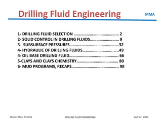
  • 1. Slayt No: 1/120Mustafa Münir ATAGÜN DRILLING FLUID ENGINEERING Drilling Fluid Engineering MMA 1- DRILLING FLUID SELECTION …………………………………… 2 2- SOLID CONTROL IN DRILLING FLUIDS……………………… 9 3- SUBSURFACE PRESSURES……………………………………….32 4- HYDRAULIC OF DRILLING FLUIDS………………………. …..49 4- OIL BASE DRILLING FLUID………………………………………. 66 5-CLAYS AND CLAYS CHEMISTRY………………………………… 80 6- MUD PROGRAMS, RECAPS…………………………………….. 98
  • 2. Slayt No: 2/120Mustafa Münir ATAGÜN DRILLING FLUID ENGINEERING Drilling Fluid Engineering DRILLING FLUID SELECTION: Drilling fluid selection for a particular well starts with a full consideration of all the factors mentioned below.. The study should include examining well records from nearby wells, looking at the type of drilling fluid used, and any fluid related problems which might have been experienced. This could range from slow ROP’s to Hole Stability issues, to Reservoir Damage. It is not subject within the scope of this section go deeply into the drilling fluid selection factors. The intention is to introduce to you with the factors for selection the Drilling Fluids. MMA
  • 3. Slayt No: 3/120Mustafa Münir ATAGÜN DRILLING FLUID ENGINEERING DRILLING FLUID SELECTION 1- ABNORMAL PRESSURES: To prevent the rock from failing mechanically at the borehole (sloughing or caving), and to prevent fluids within permeable zones from flowing into the borehole, a sufficient pressure must be maintained by the drilling fluid to at least balance the fluid, or pore, pressure within the rock. Balancing the physical stresses that effect wellbore stability then, are simply a matter of adjusting the Mud Weight. 2- ACTIVE CLAYS: It is impossible to prevent hydration of shale formation when using a water based drilling fluid. This is because, while Osmotic Forces may be overcome by adding salt to the mud, there is no way to counter the Clay Mineral Hydration force, when drilling with a water based fluid. Further, water may be sucked into the formation from Invert Emulsion Oil and Synthetic base muds, if an inadequate water phase salinity is run. As a general rule, deeper, hotter and older shale is less chemically reactive than younger, shallower and cooler clay sediment. It should be obvious that these factors need to be taken into consideration when planning a Drilling Fluid Program, particularly if planning to use a water base mud. 3- HIGH TEMPERATURES: From the drilling fluid point of view high temperatures can be considered as those above which conventional drilling fluid additives begin to thermally degrade at an appreciable rate. The degradation leads to loss of product function, and system maintenance becomes difficult and expensive. MMA
  • 4. Slayt No: 4/120Mustafa Münir ATAGÜN DRILLING FLUID ENGINEERING DRILLING FLUID SELECTION 4- DRILLING AND CLEANING THE HOLE: The choice of Drilling Fluid will effect the potential Rate of Penetration. Drilling Fluid Properties are also critical to Hole Cleaning. It is useful to have an understanding of the mechanisms involved both in selecting and designing the Fluid for a specific well, and in getting the most out of the Fluid being used. 5- RATE OF PENETRATION: The choice of Drilling Fluid will effect the potential Rate of Penetration. Drilling Fluid Properties are also critical to Hole Cleaning. It is useful to have an understanding of the mechanisms involved both in selecting and designing the Fluid for a specific well, and in getting the most out of the Fluid being used. This relationship varies considerably between conventional roller cone bits, and the more modern PDC drag bits. 6- CUTTINGS TRANSPORT / HOLE CLEANING : The transportation of the cuttings from bit to surface has always been one of the main functions of drilling fluids. The relationship of mud rheology to cuttings transport in vertical holes has been understood for a long time. In deviated holes however, other factors aside from the “carrying capacity” of the mud come into play. Cutting properties is also effect the hole cleaning and ROP related with the mud selection. MMA
  • 5. Slayt No: 5/120Mustafa Münir ATAGÜN DRILLING FLUID ENGINEERING DRILLING FLUID SELECTION 7- CUTTINGS PROPERTIES: Researchers who experimented with different density cuttings found that the greater the density, the greater the tendency to settle out, and the harder to remove. The density and other properties of the cuttings affect the cleaning of the well. While mud selection it must be considered. 8- HYDRAULİC: Hydraulics is defined as “the physical science and technology of the static and dynamic behavior of fluids”. In this section we are concerned with pumping Drilling Fluids from the mud tanks, through surface lines and hoses, down the drill string, and circulating it back up the annulus. A certain increment of pressure is required to move the mud through each section of the circulating system. The pressure required to circulate a fluid through a particular section of pipe or hose, depends on cross sectional area and length of the tubular section, the physical properties of density and rheology of the fluid, and the flow rate. In a Drilling Fluid, the Rheology defines the flow properties of that fluid. MMA
  • 6. Slayt No: 6/120Mustafa Münir ATAGÜN DRILLING FLUID ENGINEERING DRILLING FLUID SELECTION 9- FORMATION DAMAGE:: As a drill bit cuts a permeable zone, and fresh virgin rock is exposed to the drilling fluid, there is initially a spurt of whole mud into the pores of the rock. If the particle size distribution of the solids in the mud is good, mud solids will almost instantly bridge the pore throats. Whole mud will not penetrate more than a few millimeters at most into the rock, and a filter cake will quickly be formed, restricting the flow of filtrate into the formation. 10- CORROSION: Acid conditions promote corrosion. CO2 gas and the action of bacteria on some mud products produce acids, or corrosive byproducts. Increasing pH reduces corrosion and bacterial action, and reacts out CO2, but is not always viable when drilling reactive formations. Techniques for minimizing corrosion include raising pH, using oxygen scavengers, and adding amine type products to the fluid to coat steel components and reduce reactivity. MMA
  • 7. Slayt No: 7/120Mustafa Münir ATAGÜN DRILLING FLUID ENGINEERING DRILLING FLUID SELECTION 11- LUBRICITY: Lubricity is generally not a problem with oil or Synthetic base muds. High torque can be a problem in some water based drilling fluids, mainly those with a low solids content. Solid particles within drilling fluids are the main source of lubricating properties. Emulsified fluids act as finely divided particles and have the same effect. Diesel oil added to water base mud has an initial lubricating effect, not from the properties of the oil, but as a particle within the fluid 12- GAS HYDRATE: Gas hydrates are solid mixtures of gas and water, which react to form a rigid lattice type structure. They form, usually at the seabed, due to a combination of high hydrostatic pressures, and low seabed temperatures. High fluid velocities, and pressure pulses may also contribute to hydrate formation. They may form above the freezing temperature of water. Oil and Synthetic base muds, which have high CaCl2 water phase salinities will not exhibit hydrate formation problems. Hydrates can however form in these muds if the water phase salinity is too low. This should not be a problem in any Unocal operation. MMA
  • 8. Slayt No: 8/120Mustafa Münir ATAGÜN DRILLING FLUID ENGINEERING DRILLING FLUID SELECTION MMA
  • 9. Slayt No: 9/120Mustafa Münir ATAGÜN DRILLING FLUID ENGINEERING SOLID CONTROL IN DRILLING FLUIDS Introduction Laboratory tests and practical field experience show that closely monitoring drilled solids in the mud and minimizing their concentration can result in large savings of both money and time. These savings manifest in three ways: Improved drilling rate Increased bit life Reduced wear on mud pumps. MMA Solids control methods are based on the average diameters of the particles being handled: Coarse Particles: Greater than 2000 microns Intermediate Particles: From 250 and 2000 microns Medium Particles: from 75 to 249 microns Fine Particles: from 45 to 74 microns Ultra-fine Particles: from 2 to 44 microns Collodial Particles: less than 2 microns
  • 10. Slayt No: 10/120Mustafa Münir ATAGÜN DRILLING FLUID ENGINEERING SOLID CONTROL IN DRILLING FLUIDS MMA
  • 11. Slayt No: 11/120Mustafa Münir ATAGÜN DRILLING FLUID ENGINEERING SOLID CONTROL IN DRILLING FLUIDS MMA
  • 12. Slayt No: 12/120Mustafa Münir ATAGÜN DRILLING FLUID ENGINEERING SOLID CONTROL IN DRILLING FLUIDS SETTLING: Treatment of solids-related mud problems may involve one or more of the following mechanisms: settling, dilution, mechanical separation and chemical treatment. Settling involves retaining mud in a nearly quiescent state long enough to allow the undissolved solids, which are heavier than water, to "fall out" of the fluid. The relative success of this method depends on several factors, including the size and shape of the particles, the density of the particles, the density of the fluid, and the overall retention (settling) time. The settling time can be reduced by using a flocculant to increase the particle size, or by inducing centrifugal force to increase the gravitational effect. MMA
  • 13. Slayt No: 13/120Mustafa Münir ATAGÜN DRILLING FLUID ENGINEERING SOLID CONTROL IN DRILLING FLUIDS Dilution, unlike the other solids control methods, does not involve removing solid particles from the mud; rather, it is a means of decreasing the solids concentration by adding base fluid to the system. Dilution is most often used to correct mud properties that have been altered by the accumulation of drilled solids. The drawback to this method is that as drilling progresses, concentrations of drilled solids continue to increase, and undesirable mud properties eventually reappear. Also, dilution is often expensive for the following reasons: The consumption of the products required to maintain desired mud properties is continually increasing. Lack of storage space for the increased mud volume often leads to the discarding of hundreds of barrels of valuable drilling mud. Extra cleanup and transportation costs are incurred in environmentally sensitive areas. MMA
  • 14. Slayt No: 14/120Mustafa Münir ATAGÜN DRILLING FLUID ENGINEERING SOLID CONTROL IN DRILLING FLUIDS Mechanical separation devices are available in two basic types: vibrating screening devices (shakers) and systems that use centrifugal force to increase settling rate. Mechanical treatment of solids buildup is often the most practical and cost effective of the four available methods—it does not alter essential mud properties and it decreases the need for dilution. Generally speaking, the greater the cost per barrel of a given mud, the greater the savings in using mechanical equipment to rectify mud properties. The equipment used to mechanically remove solids from the mud must be designed to fit the requirements of a given drilling operation; not every piece of equipment is appropriate in every situation. Furthermore, the equipment specifically selected to aid in mechanical removal of solids must be rigged up and maintained to ensure that the units operate at peak performance. MMA
  • 15. Slayt No: 15/120Mustafa Münir ATAGÜN DRILLING FLUID ENGINEERING SOLID CONTROL IN DRILLING FLUIDS Shale Shakers: The double-decker shale shaker has two screens mounted on a flat- bed construction. The screens can range down to 100 mesh with the mesh cross section varying from square to an exaggerated rectangle. Drilled solids down to 177 microns are removed by 80-mesh screens, and 840-micron size particles by 20-mesh screens. MMA
  • 16. Slayt No: 16/120Mustafa Münir ATAGÜN DRILLING FLUID ENGINEERING SOLID CONTROL IN DRILLING FLUIDS Desilters and Desanders: The desilters/desanders must be equipped with centrifugal pumps capable of providing sufficient pressure to the hydrocyclones to allow them to operate in the desired pressure range. When correctly installed and operating in the design range, desilters and desanders are capable of removing up to 95% of solid particles larger than 15 microns. MMA
  • 17. Slayt No: 17/120Mustafa Münir ATAGÜN DRILLING FLUID ENGINEERING SOLID CONTROL IN DRILLING FLUIDS Centrifuge: In weighted mud systems it is often desirable to reduce mud maintenance costs by methods other than dilution. Since it is not practical to use desilting equipment in these systems, a centrifuge is often used. Mud centrifuges work on the decanting principle. The mud flow enters a chamber rotating at a high speed, and centrifugal force separates the mud stream into three components: fluid phase, low-specific-gravity solids, and high-specific-gravity solids. Following separation of the low-gravity solids, the high-gravity solids are returned to the active mud system. In unweighted mud systems, a high-volume decanting centrifuge removes low-specific- gravity drilled solids most efficiently and economically. The centrifuge can be operated on unweighted muds at speeds up to 2200 to 2400 rpm, creating centrifugal forces greater than 1500 G-force. The high-volume centrifuge can remove fine solids down to two microns (e.g., bentonite and clays) . The separation efficiency of hydrocyclones depends on four general factors: 1. Fluid properties; 2. Particle properties; 3. Flow parameters; 4. Hydrocyclone parameters. MMA
  • 18. Slayt No: 18/120Mustafa Münir ATAGÜN DRILLING FLUID ENGINEERING
  • 19. Slayt No: 19/120Mustafa Münir ATAGÜN DRILLING FLUID ENGINEERING SOLID CONTROL IN DRILLING FLUIDS MMA
  • 20. Slayt No: 20/120Mustafa Münir ATAGÜN DRILLING FLUID ENGINEERING SOLID CONTROL IN DRILLING FLUIDS MMA
  • 21. Slayt No: 21/120Mustafa Münir ATAGÜN DRILLING FLUID ENGINEERING Barium sulfate (barite) is the primary additive used to increase the density of clay/water muds. Densities ranging from 9 – 19 lbm/gal can be obtained using mixtures of barium sulfate, clay, and water. The specific gravity of pure barium fulfate is 4.5, but the commercial grade used in drilling fluids (API barite) has an average specific gravity of about 4.2. Recently, alternative density control agents such as hematite (Fe2O3) with specific gravity ranging from 4.9 to 5.3 and ilmenite (FeO.TiO2), with specific gravity ranging from 4.5 to 5.1 have been introduced. Because of their hardness, there is a concern about the abrasive of these materials in the circulating system. SOLID CONTROL IN DRILLING FLUIDS Density control MMA
  • 22. Slayt No: 22/120Mustafa Münir ATAGÜN DRILLING FLUID ENGINEERING SOLID CONTROL IN DRILLING FLUIDS The mixture density is given by If the storage capacity is available, to increase the density of the drilling fluid, we simply add barite to the mud. Therefore, the known and unknown variables in this case are: Known: V1, r1, rB, r2 Unknown: V2, mB MMA r1, V1 r2, V2 rB, VB
  • 23. Slayt No: 23/120Mustafa Münir ATAGÜN DRILLING FLUID ENGINEERING SOLID CONTROL IN DRILLING FLUIDS For ideal mixing the volume of mud, V1 and weight material, VB, must sum to the desired new volume, V2 Likewise, the total mass of mud and weight material must sum to the desired density-volume product Solving these equations simultaneously for unknowns V2 and mB yields MMA
  • 24. Slayt No: 24/120Mustafa Münir ATAGÜN DRILLING FLUID ENGINEERING SOLID CONTROL IN DRILLING FLUIDS The addition of large amounts of API barite to the drilling fluid can cause the drilling fluid to become quite viscous. The finely divided API barite has an extremely large surface area and can absorb a significant amount of free water in the drilling fluid. This problem can be overcome by adding water with the weight material to make up for the water adsorbed on the surface of the finely divided particles. It is often desirable to add only the minimum water required to wet the surface of the weight material. The addition of approximately 1 gallon of water per 100 lbm of API barite is usually sufficient to prevent an unacceptable increase in fluid viscosity. Mass balance MMA
  • 25. Slayt No: 25/120Mustafa Münir ATAGÜN DRILLING FLUID ENGINEERING SOLID CONTROL IN DRILLING FLUIDS Solving these equations for unknowns V1 and mB gives Note that VwB is the volume of water need to add with one pound of barite. VwB = 0.01 For mB pounds of barite, VwB = 0.01 mB. MMA
  • 26. Slayt No: 26/120Mustafa Münir ATAGÜN DRILLING FLUID ENGINEERING SOLID CONTROL IN DRILLING FLUIDS MMA
  • 27. Slayt No: 27/120Mustafa Münir ATAGÜN DRILLING FLUID ENGINEERING SOLID CONTROL IN DRILLING FLUIDS MMA Example-1: is desired to increase the density of 200 bbl of 11-lbm/gal mud to 11.5 lbm/gal using API barite. The final volume is not limited. Compute the weight of API barite required. Solution: The final volume is given The weight barite required For a final volume of 800 bbl. V1 is given Thus, 99.47 bbl of mud should be discarded before adding any API barite. The mass of API barite needed is given by The volume of water to be added with the barite 0.01mB = 1,083 gal or 25.79 bbl.
  • 28. Slayt No: 28/120Mustafa Münir ATAGÜN DRILLING FLUID ENGINEERING SOLID CONTROL IN DRILLING FLUIDS MMA
  • 29. Slayt No: 29/120Mustafa Münir ATAGÜN DRILLING FLUID ENGINEERING SOLID CONTROL IN DRILLING FLUIDS Poor Boy Degasser MMA
  • 30. Slayt No: 30/120Mustafa Münir ATAGÜN DRILLING FLUID ENGINEERING SOLID CONTROL IN DRILLING FLUIDS Vacum Type Degasser MMA
  • 31. Slayt No: 31/120Mustafa Münir ATAGÜN DRILLING FLUID ENGINEERING SOLID CONTROL IN DRILLING FLUIDS Three Phase Degasser MMA
  • 32. Slayt No: 32/120Mustafa Münir ATAGÜN DRILLING FLUID ENGINEERING Subsurface Pressures Pressure MMA Stress/pressure What is the difference? •Pressure - Scalar quantity •Stress - Tensor quantity •Pressure – in fluids •Stress – in solid bodies
  • 33. Slayt No: 33/120Mustafa Münir ATAGÜN DRILLING FLUID ENGINEERING Subsurface Pressures Hydrostatic Pressure MMA
  • 34. Slayt No: 34/120Mustafa Münir ATAGÜN DRILLING FLUID ENGINEERING Subsurface Pressures Hydrostatic Pressure In Drilling Wells MMA
  • 35. Slayt No: 35/120Mustafa Münir ATAGÜN DRILLING FLUID ENGINEERING Subsurface Pressures MMA Drilling a hole through a rock formation interrupts the pattern of stresses present within the rock. These stresses have both horizontal and vertical components, and are generally present due to the vertical loading, or overburden load, upon a given point within the rock. During a period of erosion and sedimentation, grains of sediment are continuously building up on top of each other, generally in a water filled environment. As the thickness of the layer of sediment increases, the grains of the sediment are packed closer together, and some of the water is expelled from the pore spaces. However, if the pore throats through the sediment are interconnecting all the way to surface the pressure of the fluid at any depth in the sediment will be same as that which would be found in a simple colom of fluid. This pressure is called NORMAL PRESSURE and only dependents on the density of the fluid in the pore space and the depth of the pressure measurement (equal to the height of the colom of liquid). it will be independent of the pore size or pore throat geometry. Normal Pressure
  • 36. Slayt No: 36/120Mustafa Münir ATAGÜN DRILLING FLUID ENGINEERING Subsurface Pressures MMA The vertical pressure at any point in the earth is known as the overburden pressure or geostatic pressure. The overburden pressure at any point is a function of the mass of rock and fluid above the point of interest. In order to calculate the overburden pressure at any point, the average density of the material (rock and fluids) above the point of interest must be determined. The average density of the rock and fluid in the pore space is known as the bulk density of the rock Overburden Pressure
  • 37. Slayt No: 37/120Mustafa Münir ATAGÜN DRILLING FLUID ENGINEERING Subsurface Pressures MMA
  • 38. Slayt No: 38/120Mustafa Münir ATAGÜN DRILLING FLUID ENGINEERING Subsurface Pressures Normal Pressure MMA The altitude which is generally used during drilling operations is the drill floor elevation but a more general altitude, used almost universally, is Mean Sea Level, MSL. When the pore throats through the sediment are interconnecting, the pressure of the fluid at any depth in the sediment will be same as that which would be found in a simple column of fluid and therefore the pore pressure gradient is a straight line. The gradient of the line is a representation of the density of the fluid. Hence the density of the fluid in the pore space is often expressed in units of psi/ft.
  • 39. Slayt No: 39/120Mustafa Münir ATAGÜN DRILLING FLUID ENGINEERING Subsurface Pressures MMA Normal Pressure – Overburden Pressure
  • 40. Slayt No: 40/120Mustafa Münir ATAGÜN DRILLING FLUID ENGINEERING Subsurface Pressures Pore pressures which are found to lie above or below the “normal” pore pressure gradient line are called abnormal pore pressures. These formation pressures may be either Subnormal (i.e. less than 0.465 psi/ft) or Overpressured (i.e. greater than 0.465 psi/ft). Compaction is a slow process of increasing load from above, re- alignment of clay particles, and gradual expulsion of fluid from the rock, with resulting decrease in porosity and increase in density. In this process if excess fluid is trapped in the rock, the formation water may take up more than its share of the overburden load, and by definition, be abnormally pressured. The mechanisms which generate these abnormal pore pressures can be quite complex and vary from region to region. However, the most common mechanism for generating overpressures is called Undercompaction and can be best described by the undercompaction model. MMA Abnormal Pressure
  • 41. Slayt No: 41/120Mustafa Münir ATAGÜN DRILLING FLUID ENGINEERING Subsurface Pressures Abnormal Pressure MMA The weight material barite required
  • 42. Slayt No: 42/120Mustafa Münir ATAGÜN DRILLING FLUID ENGINEERING Subsurface Pressures MMA (a) Formation Foreshortening During a compression process there is some bending of strata. The upper beds can bend upwards, while the lower beds can bend downwards. The intermediate beds must expand to fill the void and so create a subnormally pressured zone. This is thought to apply to some subnormal zones in Indonesia and the US. Notice that this may also cause overpressures in the top and bottom beds. Subnormal Formation Pressure Causes of Subnormal Pressure
  • 43. Slayt No: 43/120Mustafa Münir ATAGÜN DRILLING FLUID ENGINEERING Subsurface Pressures MMA (b) Thermal Expansion: As sediments and pore fluids are buried the temperature rises. If the fluid is allowed to expand the density will decrease, and the pressure will reduce. (c) Depletion: When hydrocarbons or water are produced from a competent formation in which no subsidence occurs a subnormally pressured zone may result. This will be important when drilling development wells through a reservoir which has already been producing for some time. Some pressure gradients in Texas aquifers have been as low as 0.36 psi/ft Subnormal Formation Pressure
  • 44. Slayt No: 44/120Mustafa Münir ATAGÜN DRILLING FLUID ENGINEERING (d) Potentiometric Surface: This mechanism refers to the structural relief of a formation and can result in both subnormal and overpressured zones. The potentiometric surface is defined by the eight to which confined water will rise in wells drilled into the same aquifer. The potentiometric surface can therefore be thousands of feet above or below ground level MMASubsurface Pressures
  • 45. Slayt No: 45/120Mustafa Münir ATAGÜN DRILLING FLUID ENGINEERING (a) Incomplete sediment compaction or undercompaction: is the most common mechanism causing overpressures. In the rapid burial of low permeability clays or shales there is little time for fluids to escape. The formation pressure will build up and becomes overpressured formtion. In other words, If the burial is rapid and the sand is enclosed by impermeable barriers, there is no time for this process to take place, and the trapped fluid will help to support the overburden. (b) Faulting Faults may redistribute sediments, and place permeable zones opposite impermeable zones, thus creating barriers to fluid movement. This may prevent water being expelled from a shale, which will cause high porosity and pressure within that shale under compaction. (c) Massive Rock Salt Deposition Deposition of salt can occur over wide areas. Since salt is impermeable to fluids, the underlying formations become overpressured. Abnormal pressures are frequently found in zones directly below a salt layer. Subsurface Pressures MMA Causes of Abnormal Pressure
  • 46. Slayt No: 46/120Mustafa Münir ATAGÜN DRILLING FLUID ENGINEERING Subsurface Pressures MMA (d) Phase Changes during Compaction: Minerals may change phase under increasing pressure, e.g. gypsum (CaSO4.H2O) converts to anhydrite plus free water. It has been estimated that a phase change in gypsum will result in the release of water. The volume of water released is approximately 40% of the volume of the gypsum. If the water cannot escape then overpressures will be generated. Conversely, when anhydrite is hydrated at depth it will yield gypsum and result in a 40% increase in rock volume. The transformation of montmorillonite to illite also releases large amounts of water. (e) Repressuring from Deeper Levels: This is caused by the migration of fluid from a high to a low presssure zone at shallower depth. This may be due to faulting or from a poor casing/cement job. The unexpectedly high pressure could cause a kick, since no lithology change would be apparent. High pressures can occur in shallow sands if they are charged by gas from lower formations. (f) Generation of Hydrocarbons: Shales which are deposited with a large content of organic material will produce gas as the organic material degrades under compaction. If it is not allowed to escape the gas will cause overpressures to develop. The organic by- products will also form salts which will be precipitated in the pore space, thus helping to reduce porosity and create a seal.
  • 47. Slayt No: 47/120Mustafa Münir ATAGÜN DRILLING FLUID ENGINEERING Subsurface Pressures MMA When two aqueous fluids as shown below having different salinities are exposed to each other, there is a tendency for the less salty fluid to dilute the more salty fluid, due to Osmotic Force. When a hole is drilled through a shale, if the Drilling Fluid contains less salt than the shale, there will be a tendency for water to migrate into the shale. This will cause swelling and failure of the rock. Osmotic Pressure
  • 48. Slayt No: 48/120Mustafa Münir ATAGÜN DRILLING FLUID ENGINEERING Subsurface Pressures MMA Fracture pressure is the pressure in the wellbore at which a formation will crack The stress within a rock can be resolved into three principal stresses. A formation will fracture when the pressure in the borehole exceeds the least of the stresses within the rock structure. Normally, these fractures will propagate in a direction perpendicular to the leastss. At sufficient depths (usually below 1000 m or 3000 ft) the minimum principal stress is horizontal; therefore, the fracture faces will be vertical. For shallow formations, where the minimum principal stress is vertical, horizontal (pancake) fractures will be created. Fracture Pressure
  • 49. Slayt No: 49/120Mustafa Münir ATAGÜN DRILLING FLUID ENGINEERING Hydraulics of Drilling Fluids MMA Mud-Weight Equivalent, also known as Equivalent Mud Weight (EMW) is the total amount of pressure exerted at a true vertical depth which is denoted in the mud density. The formation during circulation can hold a specific mud weight and pressure. This amount of mud weight is referred to as Mud- Weight Equivalent. Hydrostatic Pressure of in fluid column if Po = 0 Hydrostatic Pressure in Fluid Column 0052.0 pDp  r Dp 052.0 r D p 052.0 rThe fluid density Example: Calculate the static mud density required to prevent flow from a permeable stratum at 12,200ft if the pore pressure of the formation fluid is 8500psig. Solution: The mud density must be at least 13.4 lbm/gal gallbm D p /4.13 200,12052.0 8500 052.0   r
  • 50. Slayt No: 50/120Mustafa Münir ATAGÜN DRILLING FLUID ENGINEERING Hydraulics of Drilling Fluids MMA Hydrostatic Pressure in Gas Column Hydrostatic pressure of the column İdeal gas equation Finally dDdp r052.0 TR M m ZTRnZpV  TZ3.80 pM ZRT pM V m r dD Mp dp TZ80.3 052.0    D D dD M 00 TZ1544p dpp p TZ1544 )( 0 0DDM epp   P0 P0 + dP
  • 51. Slayt No: 51/120Mustafa Münir ATAGÜN DRILLING FLUID ENGINEERING Hydraulics of Drilling Fluids MMA A well contains tubing filled with methane gas (MW = 16) to a vertical depth of 10000ft. The annular space is filled with a 9.0 lbm/gal brine. Assuming ideal gas behavior, compute the amount by which the exterior pressure on the tubing exceeds the interior tubing pressure at 10,000ft if the surface tubing pressure is 1000 psia and the mean gas temperature is 140F. If the collapse resistance of the tubing is 8330 psi, will the tubing collapse due to the high external pressure? The pressure in the annulus (external pressure) at D = 10,000 ft is P2 = 0.052 * 9.0 * 10,000 + 14.7 = 4,695 psia The pressure in the tubing (internal pressure) at D = 10,000ft Pressure difference = p2 – p = 4695 – 1188 = 3507 < 8330 psia The tubing will withstand the high external pressure Hydrostatic Pressure in Gas Column psiae DDM epp 11881000 TZ1544 )0( 0 )140460(*1544 10000*16    
  • 52. Slayt No: 52/120Mustafa Münir ATAGÜN DRILLING FLUID ENGINEERING Hydraulics of Drilling Fluids MMA The effective density exerted by a circulating fluid against the formation that takes into account the pressure drop in the annulus above the point being considered. The ECD is calculated as: r – mud density, ppg P – Sum of the hydrostatic pressure and the frictional pressure drop in the annulus between the depth D and surface, Psig D – the true vertical depth, ft Example: A 9.5-PPG drilling fluid is circulated through the drill pipe and the annulus. The frictional pressure losses gradient in the annulus is 0.15. Calculate the equivalent circulating density in PPG. Solution: r = 9.5 + P/0.052 = 9.5 + 0.15 / 0.052 = 12.4 PPG Equivalent Circulating Density (ECD)
  • 53. Slayt No: 53/120Mustafa Münir ATAGÜN DRILLING FLUID ENGINEERING Hydraulics of Drilling Fluids MMA Flow Rate WHERE v = average velocity, ft/s q = flow rate, gal/min d = internal diameter of pipe, in. d2 = internal diameter of outer pipe or borehole, in. d1 =external diameter of inner pipe, in. 2 448.2 d q v   2 1 2 2448.2 dd q v   Annular Flow Pipe Flow Flow rate is one of the main factors affecting hole cleaning. More flow rate is not always the way to improve hole cleaning because might cause erosion or hole washout, therefore enlarging the hole causing less annular velocity and decreasing cuttings transport. Below a useful table showing the recommended flow rate for highly deviated and horizontal wells:
  • 54. Slayt No: 54/120Mustafa Münir ATAGÜN DRILLING FLUID ENGINEERING Hydraulics of Drilling Fluids MMA Buoyancy The behavior of an object submerged in a fluid is governed by Archimedes' Principle. Archimedes determined that a body which is completely or partially submerged in a fluid experiences an upward force called the Buoyant Force, B , which is equal in magnitude to the weight of the fluid displaced by the object. This principle can be used to explain why ships, loaded with millions of kilograms of cargo, are able to float.        o l oe WW r r 1 We ,: effective weight, W: weight of the object in air, Wbo: Buoyant force. rl , ro: densities of liquid and the object
  • 55. Slayt No: 55/120Mustafa Münir ATAGÜN DRILLING FLUID ENGINEERING Hydraulics of Drilling Fluids MMA 10,000 ft of 19.5-lbm/ft drillpipe and 600 ft of 147 lbm/ft drill collars are suspended off bottom in a 15-lbm/gal mud. Calculate the effective hook load that must be supported by the derrick. Density of steel is 65.5 lbm/gal Solution: W = 19.5 * 10000 + 147 * 600 = 283200 lbm We = W(1 - rf/rs) = 283200*(1 - 15/65.5)= 218300 lbm (density of steel = 65.5 lbm/gal = 490lbm/cu ft) W Fb PT Pb H +
  • 56. Slayt No: 56/120Mustafa Münir ATAGÜN DRILLING FLUID ENGINEERING Hydraulics of Drilling Fluids 1.48 MMA Efficient cuttings transport and hole cleaning is a very important factor that must be considered during drilling operations. In inclined and horizontal drilling, hole cleaning is a common issue since there is high tendency for formation of cuttings bed in the hole which can lead to several complex problems. The optimization of cuttings transport depends on so many factors like hole angle, cutting size, drill string rotation, drill pipe eccentricity, bit hydraulics ( flow rate, anulus velocity, slip velocity, nozzle velocity, jet impact force, bit hydraulic horse power) etc. Here is a rule of thumb for optimization and cleanin the hole for roller cone bits. Jet Velocity- Jet Impact Force
  • 57. Slayt No: 57/120Mustafa Münir ATAGÜN DRILLING FLUID ENGINEERING Hydraulics of Drilling Fluids MMA Pressure drop across the bit factorcorrectionC p Cv d b dn 10074.8 4      r 22 d 2-5 C 10*8.311 t bit A q Δp r  ti i n n n A q A q A q A q A q A q v   .... 3 3 2 2 1 1 Assuming a constant Pb velocity through all the nozzles pqcF dj  r01823.0Hydraulic İmpact Force
  • 58. Slayt No: 58/120Mustafa Münir ATAGÜN DRILLING FLUID ENGINEERING Hydraulics of Drilling Fluids MMA Example: A 12.0 lbm/gal drilling fluid is flowing through a bit containing three 13/32 in nozzles at a rate of 400 gal/min. Calculate the pressure drop across the bit and the impact force developed by the bit. Solution: Assume Cd = 0.95 Total Nozzle Area Pressure Drop Hydraulic impact force: 2 2 3889.0 32 13 4 3 inAt         psi A q Δp t bit 1169 3889.0*95.0 400*12*10*311.8 C 10*8.311 22 25 22 d 2-5  r lbfpqcF dj 820169,1*1240095.001823.001823.0  r
  • 59. Slayt No: 59/120Mustafa Münir ATAGÜN DRILLING FLUID ENGINEERING Hydraulics of Drilling Fluids MMA Pseudoplastic (Time-independent shear thinning fluids) If the apparent viscosity decreases with increasing shear rate. Dilatant (Time-independent shear thickening fluids) If the apparent viscosity increases with increasing shear rate Thixotropic (Time-dependent shear thinning fluids): If the apparent viscosity decreases with time after the shear rate is increased to a new constant value Rheopectic (Time-dependent shear thickening fluids): If the apparent viscosity increases with time after the shear rate is increased to a new constant value Drilling fluids and cement slurries are generally thixotropic or time-dependent thinning or time-dependent thickening Fluid Type
  • 60. Slayt No: 60/120Mustafa Münir ATAGÜN DRILLING FLUID ENGINEERING Hydraulics of Drilling Fluids • Newtonian fluids: • Power law fluids: • Bingham fluids: • Herschel-Bulkley (Yield power law fluids) Flow curves of time-independent fluids n y K   py  n K    Rheological Model MMA
  • 61. Slayt No: 61/120Mustafa Münir ATAGÜN DRILLING FLUID ENGINEERING Hydraulics of Drilling Fluids Type Of Flow Laminar Flow Flow pattern is linear (no radial flow)  Velocity at wall is ZERO  Produces minimal hole erosion *Mud properties strongly affect pressure losses *Preferred flow type for annulus(in vertical wells) *Laminar flow is sometimes referred to as sheet flow, or layered flow. * As the flow velocity increases, the flow type changes from laminar to turbulent. Turbulent flow criteria is Reynold number: Turbulent Flow  Flow pattern is random (flow in all directions)  Tends to produce hole erosion  Results in higher pressure losses takes more energy  Provides excellent hole cleaning…but Mud properties have little effect on pressure losses Is the usual flow type inside the drill pipe and collars Thin laminar boundary layer at the wall μ dvρ928 N _ Re  cp.fluid,ofviscosityμ inI.D.,piped ft/svelocity,fluidavg.v lbm/galdensity,fluidρwhere _     MMA
  • 62. Slayt No: 62/120Mustafa Münir ATAGÜN DRILLING FLUID ENGINEERING Hydraulics of Drilling Fluids When an operator felt that the hole was not being cleared of cuttings at a satisfactory rate, he would: Increase the circulation rate Thicken the mud (increase YP/PV) Turbulent flow cleans the hole better.  Pipe rotation aids cuttings removal.  With water as drilling fluid, annular velocities of 100-125 ft/min are generally adequate (vertical wells) A relatively “flat” velocity, profile is better than a highly pointed one.  Mud properties can be modified to obtain a flatter profile in laminar flow decrease n Drilled cuttings typically have a density of about 21 lb/gal. Since the fluid density is less than 21 lb/gal the cuttings will tend to settle, or ‘slip’ relative to the drilling mud. Slip velocity of the d diameter cuttings: (ft/s) Lifting Capacity- slip Velocity  rr  2 sfs s d)(138 v MMA
  • 63. Slayt No: 63/120Mustafa Münir ATAGÜN DRILLING FLUID ENGINEERING Hydraulics of Drilling Fluids MMA
  • 64. Slayt No: 64/120Mustafa Münir ATAGÜN DRILLING FLUID ENGINEERING Hydraulics of Drilling Fluids MMA
  • 65. Slayt No: 65/120Mustafa Münir ATAGÜN DRILLING FLUID ENGINEERING Hydraulics of Drilling Fluids Drilling Fluid Circulation System MMA
  • 66. Slayt No: 66/120Mustafa Münir ATAGÜN DRILLING FLUID ENGINEERING OIL BASE DRILLING FLUID Definitions MMA
  • 67. Slayt No: 67/120Mustafa Münir ATAGÜN DRILLING FLUID ENGINEERING OIL BASE DRILLING FLUID MMA The most common base oils used have been diesel and kerosene. They have an acceptable viscosity, low flammability, and a low solvency for any rubber in the drilling system. Diesel, however, is relatively toxic, making the environmental impact of diesel-base muds generally higher than those of water- base muds. Mineral oils have replaced diesel oil and kerosene in environmentally sensitive areas of the world. Mineral oils contain a much smaller percentage of aromatics than diesel or kerosene, and thus are less toxic to marine life. There is a wide range in aromatic content in mineral oils marketed today. Crude oil can be used in oil muds; however, it has some drawbacks. For example, crude oil usually has a significant fraction of light ends, and thus exhibits low flash and fire points. Crude oil may need to be weathered prior to use. Also, crudes often contain significant amounts of asphaltenes that may present problems during drilling or completion operations, and may affect the performance of invert emulsion additives. Continuous Phase
  • 68. Slayt No: 68/120Mustafa Münir ATAGÜN DRILLING FLUID ENGINEERING OIL BASE DRILLING FLUID Emulsifiers MMA 1.60 Water present in an oil mud is in the form of an emulsion. A chemical emulsifier must be added to prevent the water droplets from coalescing and settling out of the emulsion. The emulsifier also permits water originally present in the rock destroyed by the bit to emulsify easily. A chemical wettability reversal agent is added to make the solids in the mud preferentially wet by oil rather than water. Otherwise, the solids will by absorbed by the water droplets and cause high viscosities and eventually settling of barite. The emulsified water of an oil mud tends to increase the viscosity of the mud in the same manner as inert solids. It also causes a slight increase in fluid density. Since the water is much less expensive than oil, it also decreases the total cost of an oil mud. The calcium or magnesium fatty acid soap frequently is used as an emulsifier for oil muds. Fatty acids are organic asids present in naturally occurring fats and oils that have a structure: CH3 – CH2 – (CH2)n –COOH While the fatty acid soaps are the most common type of emulsifier used in oil muds, almost any type of oil soluble soap can be used. Calcium naphthenic acid soaps and soaps made from rosin (pipe tree sap) also are common organic acid type soaps.
  • 69. Slayt No: 69/120Mustafa Münir ATAGÜN DRILLING FLUID ENGINEERING OIL BASE DRILLING FLUID MMA
  • 70. Slayt No: 70/120Mustafa Münir ATAGÜN DRILLING FLUID ENGINEERING OIL BASE DRILLING FLUID MMA
  • 71. Slayt No: 71/120Mustafa Münir ATAGÜN DRILLING FLUID ENGINEERING OIL BASE DRILLING FLUID Wettability MMA 1.63 When a drop of liquid is placed on the surface of a solid, it may spread to cover the solid surface or it may remain as a stable drop. The shape that the drop assumes depends upon the strength of the adhesive forces between molecules of the liquid and solid phases. The wettability of a given solid surface to a given liquid is defined in terms of the contact angle q. A liquid that exhibits a small contact angle has a strong wetting tendency. If q = 1800, the liquid is said to be completely nonwetting Most natural minerals are preferentially wet by water. When water-wet solids are introduced to a water-in-oil emulsion, the solids tend to agglomerate with the water, causing high viscosities and settling. To overcome this problem, wettability control agents are added to the oil phase of the mud. The wetting agents are surfactants similar to the emulsifiers. This effectively changes the solids from being preferentially wet by water to preferentially wet by oil. The soaps added to serve as emulsifiers also function to some extent as wetting agents. However, they usually do not act fast enough to handle a large influx of water-wet solids during fast drilling or mud weighting operations.
  • 72. Slayt No: 72/120Mustafa Münir ATAGÜN DRILLING FLUID ENGINEERING OIL BASE DRILLING FLUID Oil Base and Synthetic Base Muds Testing MMA 1.64 The field tests for rheology, mud density, and gel strength are accomplished in the same manner as outlined for water-based muds. The main difference is that rheology is tested at a specific temperature, usually 120°F or 150°F. Because oils tend to thin with temperature, heating fluid is required and should be reported on the API Mud Report. Sand Content: Sand content measurement is the same as for water-base muds except that the mud's base oil instead of water should be used for dilution. The sand content of oil-base mud is not generally tested. HPHT Filtration The API filtration test result for oil-base muds is usually zero. In relaxed filtrate oil-based muds, the API filtrate should be all oil. The API test does not indicate downhole filtration rates. The alternative high-temperature-high pressure (HTHP) filtration test will generally give a better indication of the fluid loss characteristics of a fluid under downhole conditions. See the figure below.
  • 73. Slayt No: 73/120Mustafa Münir ATAGÜN DRILLING FLUID ENGINEERING OIL BASE DRILLING FLUID MMA 1.65 The instruments for the HTHP filtration test consists essentially of a controlled pressure source, a cell designed to withstand a working pressure of at least 1,000 psi, a system for heating the cell, and a suitable frame to hold the cell and the heating system. For filtration tests at temperatures above 200°F, a pressurized collection cell is attached to the delivery tube. The filter cell is equipped with a thermometer well, oil-resistant gaskets, and a support for the filter paper (Whatman no. 50 or the equivalent). A valve on the filtrate delivery tube controls flow from the cell. A non-hazardous gas such as nitrogen or carbon dioxide should be used as the pressure source. The test is usually performed at a temperature of 220 -350°F and a pressure of 500 psi (differential) over a 30-minute period. When other temperatures, pressures, or times are used, their values should be reported together with test results. If the cake compressibility is desired, the test should be repeated with pressures of 200 psi on the filter cell and 100 psi back pressure on the collection cell. The volume of oil collected at the end of the test should be doubled to correct to a surface area of 7.1 inches.
  • 74. Slayt No: 74/120Mustafa Münir ATAGÜN DRILLING FLUID ENGINEERING OIL BASE DRILLING FLUID Electrical Stability : The electrical stability test indicates the stability of emulsions of water in oil mixtures. The emulsion tester consists of a reliable circuit using a source of variable AC current (or DC current in portable units) connected to strip electrodes (Figure 1.9). The voltage imposed across the electrodes can be increased until a predetermined amount of current flows through the mud emulsion-breakdown point. Relative stability is indicated as the voltage at the breakdown point and is reported as the electric stability of the fluid on the daily API test report. MMA 1.66
  • 75. Slayt No: 75/120Mustafa Münir ATAGÜN DRILLING FLUID ENGINEERING OIL BASE DRILLING FLUID Liquids and Solids Content Oil, water, and solids volume percent is determined by retort analysis as in a water-base mud. More time is required to get a complete distillation of an oil mud than for a water mud. The corrected water phase volume, the volume percent of low-gravity solids, and the oil-to-water ratio can be calculated. The volume oil-to-water ratio can be found from the procedure below: Oil fraction 100 % by volume oil or synthetic oil % by volume oil or synthetic oil - % by volume water MMA
  • 76. Slayt No: 76/120Mustafa Münir ATAGÜN DRILLING FLUID ENGINEERING OIL BASE DRILLING FLUID Chemical analysis procedures for nonaqueous fluids can be found in the API 13B bulletin available from the American Petroleum Institute. Alkalinity and Lime Content (NAF) The whole mud alkalinity test procedure is a titration method that measures the volume of standard acid required to react with the alkaline (basic) materials in an oil mud sample. The alkalinity value is used to calculate the pounds per barrel of unreacted, "excess" lime in an oil mud. Excess alkaline materials, such as lime, help to stabilize the emulsion and neutralize carbon dioxide or hydrogen sulfide acidic gases. Total Salinity (Water-Phase Salinity [WAF] for NAF) The salinity control of NAF fluids is very important for stabilizing water-sensitive shales and clays. Depending on the ionic concentration of the shale waters and of the mud water phase, an osmotic flow of pure water from the weaker salt concentration (in shale) to the stronger salt concentration (in mud) will occur. This may cause dehydration of the shale and, consequently, affect its stabilization. MMA
  • 77. Slayt No: 77/120Mustafa Münir ATAGÜN DRILLING FLUID ENGINEERING OIL BASE DRILLING FLUID Anilin Point, is the lowest temperature at which oil is completely miscible with equal volume of anilin (C6H5NH2) is called anilin point. . The aniline point (AP) correlates roughly with the amount and type of aromatic hydrocarbons in an oil sample. A low AP is indicative of higher aromatics, while a high AP is indicative of lower aromatics content. Diesel oil with AP below 120°F [49°C] is probably risky to use in oil-base mud. The API has developed test procedures that are the standard for the industry. Test Procedure: 1. Clean and dry the apparatus. Measure 4 ml of aniline and 4 ml of the oil to be tested into the test tube. 2. Place stopper into the test tube and insert thermometer, making sure the bulb does not touch the sides or bottom of the tube. 3. Heat the tube slowly while stirring the mixture (stir by moving the thermometer up and down) until complete miscibility (the mixture becomes clear) occurs. 4. Remove from heat source and continue stirring until aniline-oil mixture becomes cloudy. Read thermometer temperature at cloud point and report aniline point in °F. MMA
  • 78. Slayt No: 78/120Mustafa Münir ATAGÜN DRILLING FLUID ENGINEERING OIL BASE DRILLING FLUID MMA
  • 79. Slayt No: 79/120Mustafa Münir ATAGÜN DRILLING FLUID ENGINEERING OIL BASE DRILLING FLUID Particle-Size Distribution (PSD) Test The PSD examines the volume and particle size distribution of solids in a fluid. This test is valuable in determining the type and size of solids control equipment that will be needed to properly clean a fluid of undesirable solids. Lubricity Testing Various lubricity meters and devices are available to the industry to determine how lubricous a fluid is when exposed to steel or shale. In high-angle drilling applications, a highly lubricious fluid is desirable to allow proper transmission of weight to the bit and reduce side wall sticking tendencies. MMA
  • 80. Slayt No: 80/120Mustafa Münir ATAGÜN DRILLING FLUID ENGINEERING OIL BASE DRILLING FLUID Capillary Suction Time (CST) Inhibition testing looks at the inhibitive nature of a drilling fluid filtrate when exposed to formation shale samples. The CST is one of many tests that are run routinely on shale samples to optimize the mud chemistry of a water-base fluid. Linear-Swell Meter (LSM) Another diagnostic test to determine the inhibitive nature of a drilling fluid on field shale samples. The LSM looks at long-term exposure of a fluid filtrate to a formation shale sample. Test times for LSM can run up to 14 days. Shale Erosion Shale inhibition testing looks at the inhibitive nature of a drilling fluid and examines the erodability of a shale when exposed to a drilling fluid. Various tests procedures for this analytical tool. Return Permeability Formation damage characterization of a fluid through an actual or simulated core is accomplished with the return permeability test. This test is a must when designing specialized reservoir drilling fluids to minimize formation impairment. MMA
  • 81. Slayt No: 81/120Mustafa Münir ATAGÜN DRILLING FLUID ENGINEERING CLAYS AND CLAYS CHEMISTRY • Clays and clay minerals are very important as drilling Engineering point. 8-35 km crust 12500 km dia O = 49.2 Si = 25.7 Al = 7.5 Fe = 4.7 Ca = 3.4 Na = 2.6 K = 2.4 Mg = 1.9 other = 2.6 % by weight in crust 82.4% MMA
  • 82. Slayt No: 82/120Mustafa Münir ATAGÜN DRILLING FLUID ENGINEERING CLAYS AND CLAYS CHEMISTRY Clay particles are like plates or needles. They are negatively charged. Clays are plastic; Silts, sands and gravels are non-plastic Clays exhibit high dry strength and slow dilatancy There are three main groups of clay minerals: 1- Kaolinite - also includes dickite and nacrite; formed by the decomposition of orthoclase feldspar (e.g. in granite); kaolin is the principal constituent in china clay. 2- Illite - also includes glauconite (a green clay sand) and are the commonest clay minerals; formed by the decomposition of some micas and feldspars; predominant in marine clays and shales. 3- Smectites or montmorillonites - also includes bentonite and vermiculite; formed by the alteration of mafic igneous rocks rich in Ca and Mg; weak linkage by cations (e.g. Na+, Ca++) results in high swelling/shrinking potential MMA
  • 83. Slayt No: 83/120Mustafa Münir ATAGÜN DRILLING FLUID ENGINEERING CLAYS AND CLAYS CHEMISTRY Clay minerals are made of two distinct structural units. Basic structures of clay minerals Tetrahedral Silica Sheet: Formula of the tetrahedral sheet: Si4O6 (OH)4 negative charge: only exists in combination with cations and additional oxygens Octahedral AliminumSheet: Al2(OH)6 Formula of the octahedral sheet: Brucite: Mg3(OH)6 􀃆 all octahedrals occupied 􀃆 trioctahedral Gibbsite: Al2(OH)6 􀃆 2/3 of octahedrals occupied 􀃆 dioctahedral MMA
  • 84. Slayt No: 84/120Mustafa Münir ATAGÜN DRILLING FLUID ENGINEERING CLAYS AND CLAYS CHEMISTRY SILICATE SHEET (T) ALUMINA SHEET (O) + + + TO or 1:1KAOLINITE MONTMORILLONITE AND MICA (INCLUDE ILLITE) + + + + TOT or 2:1 CHLORITE: TOT :0: TOT or 2:1:1 ATTAPULGITE/SEPIOLITE: TOT or 2:1 Clay Structures MMA
  • 85. Slayt No: 85/120Mustafa Münir ATAGÜN DRILLING FLUID ENGINEERING Property Kaolin Mica Mont Attap Chlorite Layer type 1 : 1 2 : 1 2 : 1 2 : 1 2 : 1 : 1 Crystal Structure Sheet Sheet Sheet Sheet Sheet Particle Hexagonal Extensive Flakes Needles Plates Shape Plate Plates Particle 0.5 - 5 0.5 - Large 0.1 - 2 0.1 - 1 0.1 - 5 Size (µ) Sheets Surface Area BET-N2-m2/g 15 - 20 50 - 110 30 - 80 200 140 BET-H2O-m2/g - - 200 - 800 - - CEC-meq/100g 3 - 15 10 - 40 80 - 150 15 - 25 10 - 40 Viscosity in Water Low Low High High Low Effects of Salts Flocculates Flocculates Flocculates Little or none Flocculates Comparison of Structures CLAYS AND CLAYS CHEMISTRY MMA
  • 86. Slayt No: 86/120Mustafa Münir ATAGÜN DRILLING FLUID ENGINEERING There are over 400 mineral and rock names to describe clay minerals. Only the following are common and applicable to drilling fluids chemistry • Kaolin often hydro-termal alternation of feldspars, of volcanic ash, and is found in shales and marine – Composed of single tetrahedral sheet and single octahedral sheet – Charges within structure are balanced with few substitutions – Strong hydrogen bonding between layers limits swelling – Edge charges are sensitive to pH • Micas found in sedimentary shale sections is normally clsassed as illite – 2:1 lattice with 2 silica sheets sandwiching an octahedral layer – Ion replacement occurs in the TETRAHEDRAL layer – Charge deficiency is balanced by potassium ions – The Potassium fits neatly in the hexagonal holes made by the silica tetrahedral and securely binds the separate layers together. • Montmorillonite The most common mineral in the group of minerals called the smectites. – A 2:1 lattice structure very similar to mica – Ionic substitution occurs in the OCTAHEDRAL layer – Cations are unable to approach close enough to completely loose their ionic character – The residual ionic character provides attractive forces for adsorbing water. • Sepiolite and Attapulgite – Both consist of long needles. – They cannot swell but have a large surface are and can bind water strongly. This means that they are effective viscosifiers • Chlorite 2:1:1 lattice type mineral CLAYS AND CLAYS CHEMISTRY MMA
  • 87. Slayt No: 87/120Mustafa Münir ATAGÜN DRILLING FLUID ENGINEERING CLAYS AND CLAYS CHEMISTRY Atterberg observed that the consistency of fine-grained soils are greatly affected by the amount of moisture content present in these soils, therefore, the moisture content at which the soil changes from one state to another state is defined Consistency Limits or Atterberg Limits (Murthy, 2002). Depends on water content, fine-grained soil can exist in any of four states. A) Solid State B) Semi Solid State C) Plastic State D) Liquid State. Liquid limit: The boundary between the liquid and plastic states; Plastic limit: The boundary between the plastic and semi-solid states; Shrinkage limit: The boundary between the semi-solid and solid states. Liquid, Plastic, Shrinkage limits
  • 88. Slayt No: 88/120Mustafa Münir ATAGÜN DRILLING FLUID ENGINEERING CLAYS AND CLAYS CHEMISTRY MMA 1.78
  • 89. Slayt No: 89/120Mustafa Münir ATAGÜN DRILLING FLUID ENGINEERING CLAYS AND CLAYS CHEMISTRY 0 10 20 30 40 50 60 0 10 20 30 40 50 60 70 80 90 100 PlasticityIndex Liquid Limit A-line U-line montmorillonite kaolinite halloysite chlorite illite Plastisity Index –Liquid Limit Chart MMA 1.79
  • 90. Slayt No: 90/120Mustafa Münir ATAGÜN DRILLING FLUID ENGINEERING CLAYS AND CLAYS CHEMISTRY ++ + + Na+ Na+ Na+ Na+ Na+ Na+ Na+ Na+ Na+ K+ K+ + K+ K+ K+ Ion Exchange Properties of Clays The negative charge generated by isomorphous is balanced by cations held near the clay surface , Common charge- balancing cations are Na, K, Ca, Mg, these cations are readly exchangeable in montmorillenite. e.G KCl solution Different cations have different attractions for the exchange sites. Assuming all the cations are the same, the order of increasing replacing power of cations is generally Li+ < Na+ < K+ < Mg2+ < Ca2+ < H+ e.g. : At equal concentrations potassium will displace more sodium than sodium will displace potassium. Increasing the concentration of any given cation will increase the probability that it will displace another cation. e.g. : It is possible for high concentrations of potassium to displace calcium cations. Cation exchange capacity of clay can be measured by methylene blue test (MBT) or chemical analysis of displaced. MMA
  • 91. Slayt No: 91/120Mustafa Münir ATAGÜN DRILLING FLUID ENGINEERING CLAYS AND CLAYS CHEMISTRY *The properties of the exchange cations have an important influence on clay properties. *Hydration of cations depends on their charge and size. – High charge & small diameter cations are usually most highly hydrated – Low charge & large diameter cations are usually least hydrated *The important diameter is the hydrated ionic diameter Atom Dehydrated Ion Hydrated Ion Diameter A Diameter A Na - Sodium 1.90 11.2 K - Potassium 2.66 7.6 Cs - Cesium 3.34 7.6 Mg - Magnesium 1.30 21.6 Ca - Calcium 1.90 19.0 Hydration of Cations (Clays) MMA
  • 92. Slayt No: 92/120Mustafa Münir ATAGÜN DRILLING FLUID ENGINEERING CLAYS AND CLAYS CHEMISTRY *The most common swelling clay mineral is montmorillonite. * Montmorillonite (bentonite) is used in some drilling fluids to give viscosity and fluid loss control. * Montmorillonite is found in many reactive shales. * Montmorillonite is found in some sandstone (including reservoir sands). * The amount of water taken up by a montmorillonite (& hence the degree of swelling) depends on : – Layer charge of the clay / Ion exchange – Nature of the exchangeable cation – Nature of the external solution * Swelling promoted by highly hydrated, low charge exchangeable cations e.g.. Li+ , Na+ * Swelling reduced by high charge, less hydrated cations e.g.. Al3+ K+ reduces swelling because poorly hydrated even though low charge. Ca2+, Mg2+ reduces swelling because high charge, though highly hydrated. Clays Swelling MMA
  • 93. Slayt No: 93/120Mustafa Münir ATAGÜN DRILLING FLUID ENGINEERING CLAYS AND CLAYS CHEMISTRY relative distribution of particles with a given spacing, % relative distribution of particles with a given spacing, % High Salinity Solutions Reduce Clay Swelling Effect of Low Salt Concentration on space between sheets Effect of High Salt Concentration on space between sheets MMA
  • 94. Slayt No: 94/120Mustafa Münir ATAGÜN DRILLING FLUID ENGINEERING CLAYS AND CLAYS CHEMISTRY Clay particles in a fluid can be : – Deflocculated – Flocculated – Aggregated – Dispersed Degree of dispersion / deflocculation of clays will affect viscosity, fluid loss control and shale inhibition. There are four basic colloidal states of clay particles in a fluid : – Deflocculated. There is an overall repulsive force between the particles. This is done by ensuring all the particles have the same charge. (The particles may be aggregates) – Flocculated. There are net attractive forces for the particles and they can associate with each other to form a loose structure. – Aggregated. The clay sheets are still attached to each other and hydration has not occurred, or the hydration process has been reversed. The aggregate maybe disaggregated by hydration and or mechanical shear. – Dispersed. This is where the aggregates have all been broken down. The dispersed clays may be flocculated or deflocculated. Clay Dispersion / Deflocculation MMA
  • 95. Slayt No: 95/120Mustafa Münir ATAGÜN DRILLING FLUID ENGINEERING CLAYS AND CLAYS CHEMISTRY Edge to edge flocculated and aggregated Edge to face flocculated and aggregated Edge to edge flocculated but dispersed Edge to face flocculated but dispersed Aggregated but deflocculated Dispersed and deflocculated FlocculatedDispersed Effect of Clays in Mud: Viscosity normal Yield normal Fluid loss normal Effect of Clays in Mud: Viscosity High Yield High Fluid loss High Effect of Clays in Mud : Viscosity Normal Yield Low Fluid loss Low Effect of Clays in Mud: Viscosity Low Yield Low Fluid loss High Effect of Clays in Mud: Viscosity Low Yield High Fluid loss High Effect of Clays in Mud: Viscosity Normal Yield Normal Fluid loss High Effect of Clays in Mud: Viscosity Normal Yield High Fluid loss High Effect of Clays in Mud: Viscosity High Yield Normal Fluid loss High MMA
  • 96. Slayt No: 96/120Mustafa Münir ATAGÜN DRILLING FLUID ENGINEERING CLAYS AND CLAYS CHEMISTRY Deflocculation MMA
  • 97. Slayt No: 97/120Mustafa Münir ATAGÜN DRILLING FLUID ENGINEERING CLAYS AND CLAYS CHEMISTRY Chemical name and formulas of the compounds releated with drilling fluids MMA
  • 98. Slayt No: 98/120Mustafa Münir ATAGÜN DRILLING FLUID ENGINEERING CLAYS AND CLAYS CHEMISTRY In the normal deposition, compaction and diagenesis of sediments, a gradually increasing overburden load, forces fluid (seawater) out of the compacting clastic material. Granular sediments, such as sand and silt take up the weight of this overburden load by grain to grain contact and the integral strength of the grains. Clay type rocks on the other hand are composed of flat platelet and rod shaped materials, and the matrix tends to be compressible. Abnormal pressuring of a rock always refers to the pore pressure or the pressure of the included fluids within the rock. In shallow formations it may be due to rapid burial. In deeper shales. it is commonly caused through diagenesis of montmorillonites to Illite, releasing bound water, From the driller’s perspective, increasing pore pressure in a shale will be coincidental with increasing porosity and decreasing density. The rock will therefore drill faster. It will contain more fluid, and if some of the fluid is gas, more gas will be released from the drill cuttings into the mud. Background gas will increase. From the driller’s perspective, increasing pore pressure in a shale will be coincidental with increasing porosity and decreasing density. The rock will therefore drill faster. It will contain more fluid, and if some of the fluid is gas, more gas will be released from the drill cuttings into the mud. Background gas will increase High Pressures
  • 99. Slayt No: 99/120Mustafa Münir ATAGÜN DRILLING FLUID ENGINEERING MUD PROGRAMS, RECAPS It is usual for a Mud Program to be submitted by the Mud Company supplying the drilling fluid products and engineering service, for each well. The exception to this may be where a standard mud formulation, such as SBM, is used for all wells. In that case a general Mud Guideline document should be prepared to act as a mud program for all wells. Drilling Fluid selection should be based on a thorough evaluation of the functions that will be required of the Fluid. This evaluation should include a look at any offset well data, particularly any problems that might have been encountered, plus a look at any Geological data that is available. This may include age, type, and potential reactivity of formations to be drilled; as well as pore pressure and temperature In the situation where the Mud Company is recommending a Fluid for a particular well or series of wells, the Program should be fully detailed. It should justify the recommendation of a particular Fluid system, and fully explain the components of the system and their functions. It should give recommended mud properties and estimated mud consumption for each interval. There should be a recommended make-up range for the various products recommended, and an estimated total amount of each product to be used. Finally an estimated total cost for each interval, and for the well should be given. A good Mud Program may also include a discussion on solids control, Mud Programs
  • 100. Slayt No: 100/120Mustafa Münir ATAGÜN DRILLING FLUID ENGINEERING MUD PROGRAMS, RECAPS • A good Mud Program has the following components: A brief discussion of the well to be drilled covering any special considerations related to the selection of the recommended Mud System. A discussion of the Mud System, its functions and cost effectiveness, and why it is particularly suitable for the well to be drilled. A discussion of the mud products used to make up the recommended Mud System, what each product is, and its function in the System. A phase by phase breakdown, recommending mud properties and mud formulation for each interval. This should include an estimate of the quantity of mud that will be required to drill the interval, the amount of each product that will be required, and an estimated cost for mud for the interval. A summary of mud consumption, product requirements, and cost estimates. A list of products and quantities to be sent to the rig for the well, including contingency items such as lost circulation material. There should be a discussion on solids control. If there is a potential for lost circulation, a discussion on the type of lost circulation expected, and recommended cure procedures. There should be a discussion of products and should include recommended make up formulations for LCM pills, and recommended spotting procedures. A discussion on recommended contingency products, other than LCM. In a water base mud program, corrosion control should be discussed, and if applicable, a recommendation for corrosion control should be included – corrosion monitoring, products for corrosion control, concentrations and procedures for using the products.
  • 101. Slayt No: 101/120Mustafa Münir ATAGÜN DRILLING FLUID ENGINEERING MUD PROGRAMS, RECAPS The Drilling Fluids Recap is the Mud Engineers end of well summary of the use of mud on a particular well. A Recap should have the following elements: A recap should start with a brief well history, followed by a discussion of any mud-related problems that occurred, and recommendations for their remediation. This should include mud consumption, hole problems, lost circulation, etc. These may be on a phase by phase basis. The Recap should give tables showing mud and mud product usage by phase, and mud cost for each phase, as well as a summary of total mud and product consumption and cost. The Recap should also have tables showing Mud Properties on a day to day basis for the whole well. Finally it is common to show graphs of Depth vs. Days, Depth vs. Mud Cost, and Depth vs. Mud Weight. Mud Recapss
  • 102. Slayt No: 102/120Mustafa Münir ATAGÜN DRILLING FLUID ENGINEERING
  • 103. Slayt No: 103/120Mustafa Münir ATAGÜN DRILLING FLUID ENGINEERING
  • 104. Slayt No: 104/120Mustafa Münir ATAGÜN DRILLING FLUID ENGINEERING