Competency Training Evidence for Panel Operator Answers
1. Competency Training Evidence for Panel Operator.
ProcessAbbreviations
PV= Process variable.
SP= Set-point.
LP= Low pressure.
MP = Medium pressure.
HP= High pressure
EDC= Energy Department Control (Power station)
Cycle 1
1a. Benzole plant start-up BPP4SWP49
1. Inform all concernedparties (UsuallyRco 4 or Rco 53) there is going to be a benzole plant shutdown.
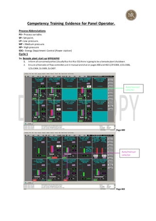
2. Ensure allbenzole oil flow controllers are in manual andshut on pages 400 and 402 1/2FiC404, 1/2LiC406,
1/2LiC404, 2LiC409, 2LiC407.
Page 400
Page 402
Auto/manual
selector
Auto/manual
selector
2. 3. Request the benzole operator (Rco53) to re-establishcirculationpumps 1+2P407/8/or 9s and2P410/12/or 11s, then
check page 466 that all required drives are on. Once thisis done open all oilflowcontrollers to establish a circulation
from scrubbers to the benzole still thento 1/2T405 thenback to scrubbers.
Page 466
4. Open control valves onpages400 and402 1+2FIC-404 lean oil flows backto 1+2C402 scrubbers from the benzole plant.
1+2LiC406 oil level control valves from the 1+2C402 scrubbers to the 1+2C401 scrubbers and1+2LiC404 oil level control
valves from 1+2C401 scrubbers to the benzole plant and2LIC-409 benzole stilllevel controller to establish circulations. 5.
5. Once circulationis established, checkon page 402 that L.P. andM.P. steam controllers 2FiC402 and2TIC-413 are in
manualand closed. Then request benzole operator (Rco 53) to confirm all block valves inandout ofthese controllers are
open.
6. Once confirmed, re-introduce M.P. steam to heater using2TIC-413 until a temperature ofat least 110°c is reached. At
110°c on L.P. steam canintroduced into the still byopening2FiC402 whilst carefullymonitoringthe benzole stillbase
pressure on page 402 aim shouldbe a stillheadof 103 andbase pressure below 200m/bar.
7. As the benzole dephlegmator temperature increases request the benzole operator to put the water back on.
Dephlegmator tempcan be seenon page 403. Whilst at the same time re-introduce water to the dephlegmator via 2TiC433
control valve onpage 403. (Aimapproximately82°c Tryto keep an approximate 50/50 oil to water ratio).
Page 403
Red = pump running.
Green = pump stopped
Dephlegmator temperature
And control valve
Phlegm oil control valve.
2.5m³/HR
3. 8. As the creosote oil temperature rises backto the washers request coolingwater pump0P435 (page 466) to be put back
in service control temperature ofoil thereafter bymanuallyoperating1T409-316 on page 402.
9. Now request 2P414 or 0P422 is startedup whilst checking that phlegm oilflowcontrol valve (2FiC405) is shut. Page 403
10. Once pumpis runningre-establishphlegmoil flow manuallyto benzole still withanaim of 2.5m3/hr. Once A steady
flow is established, 2FiC405 inautomatic control. Page 403
11. Settle plant out andthenrequest benzole operator to put benzole plant back onthe foul gas main (If operational).
Check on page 405 that 0PiC435 is nowshowing suctionof -4m/bar and not a pressure.
12. Now inform benzole operator of intentionto bringpurifier backon line.
13. Ask Benzole operator to confirm all valves “set up” andre-introduce oil flow backintopurifier via 2LIC-407 controller
on page 402 witha runninglevel aim of 50%.
14. It is goodoperations to continuallymonitor page 600 to keep aneye on L.P. steam pressure and vent systemas more
L.P. is nowbeing used, it maybe necessaryto put a turbine inservice as more L.P. steam is now beingused.
Page 600
14. Check page 466 to confirm all necessarydrives are inservice 1+2P407/8/9, 2P410/11/12, 0P435, 0P422 and 2P414.
15. Thereafter checkpages 400, 402, 403 until plant is steady. Whenplant is steadyall controllers canbe put into
automatic control.
1b.
1. Before the operator starts to openanyblockvalves ensure all valves are inmanualandalso inthe closedposition
especiallysteamvalves as a suddenburst of steam intoa cold line will cause steam hammer, possible rupture of
the line andat worst if the operator is in the vicinitytheymaybe injured or worse.
2. Ensure still headis above 110°c before introducing LPsteam.
3. Monitor still vapour pressure as it mayfluctuate if the operator has not remove all condensate from system.
4. Wait till condenser and dephlegmator temperatures beginto rise before cooling water is re-establishedas
blockages mayoccur iftheyare cold.
5. As extra steamis being usednow monitor the let-downstation as a steam turbine mayneedto be put online if
we have to import excess LPsteam.
LP let down station.Try to
maintain a central position.
4. 1a.Gas holder entry. BPP5SWP29
Note EDC will be aware of the impending entry and will lower the gas holder level accordingly overnight.
1. Contact either batterycontrol (Telephone 8106) or Rco6 to have the instrument air compressors checked to
ensure that at least 2 are inoperation and 1 is onstandby. Alsoa pressure of no lessthan5.6 barg is shownon
page 601 on the DCS.
Page 601
2. Inform Falck(8577) of the gas holder entry.
3. Confirm the base holder cabinphone andalarms are inworking order bycontactingthe base man. The base man
should call the By-Products every15 minutesandifnot thisshould be investigated.
4. Switch on the "Men ingas holder" alarmon the control room panel.
5. Inform batterycontrol there are men inthe gas holder once entrytakesplace.
6. If during the entrythe flare stackpilots fail the gasholder personnel shouldbe withdrawn. Ensure the flare stack
is controlledbyEDC.
7. Monitor the gas holder level on local andDCS instrumentationandtake actionto instruct the workingpartyto
withdrawfrom the gas holder if the level exceeds 45,000m3 (82%) or falls below 35,000m3 (64%).
8. Monitor the plant air pressure and be preparedto withdraw gasholder entryteam shouldit dropbelow 5.6barg.
9. On completionnotifythe batterycontrol andFalck. Then switchof the "Meningas holder" alarm.
1b.
1. Monitor air plant pressure at all times and be preparedto have the entryteamleave if there are problems.
(Minimum5.6mBar).
2. Although EDCwill be monitoring the gasholder level this shouldstill be done bythe control roomoperator as
well.
3. Ensure there is contact betweenthe basemanevery15 minutes andif not investigate. (8182).
Plantair/Breathingair
Pressure.Above 5.6 bar
for gas holder entry
5. 1a. SIL TEST BPP1SWP29
1. Liaise withbatterycontrol and ensure there is a batterystopbefore the tests cantake place. (8106).
2. When batterycontrol confirms theyare readyrelaythe information to the team leader (Rco4) soas the tests can
commence.
3. The team leader will start to close the outlet of the online pumpuntil the flushingliquor to the batterystarts to
drop. Once this starts to fallbelow6barg the standbypump shouldcut in to pickup the pressure. Althoughthere
is local gauges notifythe team leader the pressure is stilldroppingifthis is the case. All four pumps will be tested.
1/2p110 and 1/2p111. Page 102
Page 102
4. Once complete notifybatterycontrol that normal operations cancommence. (8106).
1b.
1. There must be a batterystop before the tests begin. (8106).
2. If the pressure continues to dropthe Team Leader (Rco4) shouldbe notifiedimmediately.
3. As this is a noisyarea ensure allradiocommunications are concise and understood.
2a. Weeklyfire fighting wet test AEMT-8DEFC3
1. Notifysecuritythat a wet test is to take place and which zone is to be tested. (6494).
2. Check the level inthe Fire fightingtank. Page 604
Stream1/2 flushing
liquorpressure
6. Page 604
3. Ensure there are no tankers or workbeing carriedout intest zone. Liaise with outside operator.
4. 0p425 runninghardwire alarm shouldlight onthe right handpanel.
5. Once the test is complete, resets hardwire panel alarms andinform securitythe wet test is complete.
2b.
1. Securitymust be informedprior to andafter test. (6494).
2. No benzole tankers to be admitted if benzole loading stationis to be tested.
3. 0p425 shouldbe operated a maximum of3 times in 1hr. whenrunningthis willshow onthe hardwire panel.
4. Occasionallyzonesother thanthe one to be testedalarm in. This must still be investigatedandthen reportedto
securityas a false alarmandalso the engineer to rectify.
5. If the hardwire alarm doesnot clear inform the outside operator to investigate.
3a. Exhauster change BPP1SWP09
Note:Exhauster changes as a panel operator is more a monitoringprocessthat requires relaying process information
to the teamleader andother members ofthe team.
1. Batterycontrol will be aware that an exhauster change is to take place andwill have stoppedpushing and
charging.
2. Ensure the detarrers are shut downbefore commencing change over. Page 166.
Fire fightingtank
level
7. Page 166
3. Once the batteryconfirms that theyare readyrelaythis to the team leader (Rco 4) that the changeover can take
place.
4. During the changeover the exhauster will be switchedinto manual bothinthe exhauster house and the control
room. Monitor the exhauster and if anyproblems arise contact the teamleader. Page 105.
Page 105
5. Once the changeover is done the team leader will radiocontrol to matchthe output signals andonce done the
exhauster canbe put back in auto.
6. The detarrers canbe restarted.
7. On completionnotifythe batterytheycanrestart. (8106)
3b.
1. The Batterymust be boxedupprior to change.
Detarrers
ExhausterAuto/ Manual
8. 2. Detarrers must be stoppedprior to change over.
3. Exhauster suction must be monitoredthroughout as above -31mBar the exhauster will trip onhighsuction.
4. Ensure the inside andoutside suctionsignals are matchedupbefore auto is selectedas this couldleadto a rapid
increase or decrease ofthe exhauster speedwhichcould ultimatelyleadto the exhauster trippingand the
batterybleeders lifting.
Cycle 2
1a. Booster change. BPP5SWP41
Note:Booster changes as a panel operator is more a monitoringprocess that requires relaying process information to the
team leader andother members ofthe team.
1. Inform EDCthat there is going to be a booster change taking place. Telephone 8297.
2. Radio the team leader (Rco 4) andinform himthat he hasthe go aheadto change the booster over.
3. Monitor the gas holder level andpressure inthe gas mainthroughout. Page 500
Page 500
4. Once complete liaisingwith the team leader tryto get the outlet gas pressure as close to the set point EDC
require before finallyputting the booster back in auto. Page 501
Gas holder level
indication
9. Page 501
5. NotifyEDCthe booster change is complete. Telephone 8297.
1b.
1. If work is being carried out inthe 11kvsubstation the booster change cannot take place as this couldpotentially
put the personor persons inharm’s way.
2. Ensure the speedof the booster is goingto be adequate to give the EDCrequiredbooster output pressure before
auto is selectedbecause if not a rapidincrease/ decrease inspeedmayhave a detrimental effect.
3. If two boosters are online ensure the speeds are matched up.
4. Gas holder level, the gas mainandthe booster pressures shouldbe monitoredthroughout.
1a. Ammonia plant start-upwith vapour valve. BPP3SWP74b.
1. The plant will alreadybe on breakwater supplytherefore reducedfeeds to Ammoniawashers to between each
just before the operational restart of the plant.
2. Ensure that 2C304 / OC305 / 1C303 / 2C303 steam controllers are inmanual and closed. DCS page 304.
Booster output set
point.
EDC booster set
point pressure.
10. Page 304
3. Ensure dephlegmator cooling water valves are inmanual and closed. Page 305.
Page 305
4. Confirm that the virginfeedcontrol valves are inmanual and are inthe closedposition, this ensuresthere is no sudden
feed of liquor to the stillswhenthe block valves are opened. DCS page 302/3/6
Dephlegmator valve
positions SP=85°c
Still steamcontrol
valvepositions
12. 4. Check that all oncoming still level controllers are inmanualandinthe closedposition. DCS page 302/3/6.
5. Start slowlywarmingup the selectedstills, byoperating in manual the lowpressure steamcontrol valves. Page
304.
Page 304
6. Monitor the pressure within the vapour pipeworkandensure the pressure is between 5Mb and70Mb at all
times. Page 306, 8/9.
7. The Production Team Leader/Operator willlet you know whenthere is a goodheadof steam at the vents and
then request the steam to be shut back off. The operator will thenclose allreflux drains andvents, thenopenthe
incinerator purge vent.
8. Make sure the operator now starts up1P319 or 2P319. These are coolingwater pumps for the free still
dephlegmator 1&2C303. Page 366
9. Open the liquor fromthe storage tanks to the selectedstill to establisha still base level. Create a strongliquor
closedcircuit circulationto the washers via the 1 or 2P314 or 315 pumps, whilst changingover from the
breakwater supply. Tryto maintaina still level and not use the drainas this will contaminate the lime sump.
10. Start slowlywarmingup the selectedstills by increasingthe LP steam control valves. Start off at 10% on each of
the stills, thencontinue to increase the steam feed to achieve a vapour pressure of between 5 Mb and70mb.
DCS page 305.
Ensure that all of the still head temperatures are above 60 degrees.
11. Adjust cooling water to Dephlegmators or steam control valve to still to help achieve this. Page 305.
Page 305
Dephlegmator cooling
water controllers
Incinerators vapour
pressure.1/2f301 will trip
at 3mbar.
LP steamcontrol
valves
13. 12. Slowlyincrease the steam flow to the free still to andmaintaina minimum of 5mbmaximum of 70 MB pressure.
13. Once there is a goodhead at the purge vent the 15 minute timer will be started. Page 308/9
14. As soonas the timer has finishedset the vapour controller OPI-324 for the desiredincinerator 1/2F301 to 20 %
output. Thenliaise withthe incinerator control room to synchronise the shuttingof the purge vent and pushing
of NH3 vapour start button.
Note:The first chamber temperature must be higher than700 degrees andthe secondchamber temperature higher
than 400 degrees before vapour canbe introducedto the incinerator. Vapour trips below3mbar.
15. There will be an instant reductionof vapour pressure, so the steamto the free ammonia still mayneedto be
increased to maintaina positive pressure withinthe vapour pipework. Trips at 3mb.
16. Once the vapour pressure andflow are establishedto the on-line incinerator, the vapour control valve output
will needto be graduallyopened to 100 % as the steams to the stills, andliquor feedto the still are gradually
increased.
17. Once the vapour valve OPI-324 is 100% open, request the operator start the caustic pumps to online stills as
required, andintroduce the virginfeedflows. Page 366.
18. Continue to warmup all stills to the normal operating parameters. Increase the virginliquor, strong liquor, steam
and water flows to the still andassociatedequipment as required. Alsoincrease / decrease the gas andair mix to
maintainthe optimum burningtemperature for the incinerator. Page 308/9
Page 309
Note, none ofthe still steam control valves canbe put into auto mode until OPI-324 is at 100% output, otherwise any
steam controller put in automode willdefault to manual andzerooutput, causingthe vapour pressure to fall, possibly
trippingthe plant on low vapour.
Note, once the vapour valve is set at 100% output, adjust the vapour pressure usingthe steamonly. Adjustment of
OPI-324 will result insteam defaulting to the trip, zerooutput position, ifthe openlimit is lost.
1b.
1. Ensure the no entryto the ammonia plant board is in place andanyone taggedon signs out and removes there
tag.
2. Before the Ammonia operator starts to openanyblockvalves ensure all valves are inmanualandalso inthe
closedpositionespeciallysteamvalves as a suddenburst of steam intoa cold line will cause steam hammer,
possible rupture of the line andat worst ifthe operator is inthe vicinitytheymaybe injuredor worse.
3. As extra steamis being usednow monitor the let-downstation as a steam turbine mayneedto be put online if
we have to import excess LPsteam.
4. Monitor vapour pressure as the incinerator willtripifit 100mBar or goes below3mBar.
Coke oven
gas Air
controller
Purge
timer
14. 5. Still temperature shouldbe maintainedabove 60°ᶜor the vapour cannot be introduced.
6. Take care not to introduce cooling water too quicklyto the dephlegmator as this will cause the vapour pressure
to crash.
7. Still base pressure andlevels to be monitoredthroughout.
8. Unless the vapour valve is fullyopen donot tryto put the LPsteam to the stillsinautoas this wouldtripthe
plant.
9. Monitor chamber temperatures as chamber 1 and 2 if theyfall below700°ᶜand also400°ᶜrespectivelyexceed
1275°ᶜ and chamber 2 950°ᶜthe incinerator will trip.
10. Until the ammoniaplant is stable keepona closed circuit to minimise contaminationof the lime sump
2a. Naphthalene plant shutdown.BPP2SWP08 ( Please note that at present the final systemis offline and maynot be
reinstated so thishas beenomitted fromthe procedure)
1. There maybe times when0T204 naphthalene product tankis out of service andtherefore the product will be
gettingsent to 1T404 benzole dailymake tank, if thisis the case thenthe following procedure will apply. Ifnot
request the benzole operator to redirect the naphthalene product to 1t404 and if neededemptythe naphthalene
oil receiver to 0t412.
2. Carry out a hot shot of condenser 0E202 bygoing to page 201 andputting0TIC226 inmanualand closing the
valve, whencondenser reaches 50o panel manto request the operator to stop0P218.
Page 201
3. Put L.P. steamcontrol valve 0FIC202 in manual andshut the valve. Page 201
4. Close M.P. steamcontrol valve 0TIC211 byputting in manual andclosing the valves. Page 200
Coolingwater
to condenser
LP steam
control valve.
15. Page 200
5. Take offthe oil circulationbyclosing 1+2FIC-201s and1+2LIC202s inmanual and shuttingvalves. Page 200
6. Request the operator to shut downoil circulation pumps on the system: 1+2P211 or 0P212.
7. Look at page 266 to ensure all necessarydrives are off. Once done notifythe Team Leader that the naphthalene
plant is shutdown.
Page 266
2b
1. Ensure there is a hot shot done on the condenser to keepthe temperature upas longas possible to stopthe
change of naphthalene solidifyinginthe systemwhenit cools below30°c.
2. Make sure there are nohighlevels left inany vessels whenshuttingdownflows.
3. As lesssteamis nowbeing usedalsomonitor the L Plet downstation.
2a. Benzole plant shutdown BPP4SWP48
Once aware of a complete Benzole plant shutdownthe normal course of action will be to inform the Benzole operator
about it, then provisionmust be made prior to the shutdownto dumpthe purifier to 0T412 sludge tank onpage 402
of the VDU the oil feedvalve fromthe Benzole stillto the purifier will needto be put inmanual and closed(2LIC-407),
after the purifier contents are reduced, Benzole operator will pumppurifier contents to 0T412. At this point begin a
MP Steam control
valveto main
heater
Oil flow
controller
ODT Level
controller
flow
controller
Thispage showsall
pumpsstopped
16. hot shot ofthe creosote coolers byclosing 1T409-306 on page 402 of the VDU, whenthe gas temperature leaving
1+2C402 washers is 50°c approx askBenzole operator to stop 0P435 cooling water pump.
Page 402
1. At page 402 on the VDUclose the L.P. steam control valve to the still 2FCV-402 and the M.P. steam valve to the
heater 2TIC-413 byplacing them inmanual and shuttingthe valves to zero.
2. At page 403 close dephlegmator water control valve 2TCV433 byplacing it inmanual andshutting the valve to
zero.
3. At page 403 the phlegm oil flowto the still will needto be takenoff byputting 2FCV405 in manual andshutting
the valve to zero, andthen askthe Benzole operator to thenstopeither 2P414 or 0P422, asks the Benzole
operator to thenconfirm that the water valve to the online condenser is closed.
Page 403
4. Confirm with Benzole operator that the foul gas mainis “off” (IF ONLINE) and tanks and vessels onthe Benzole
are “venting to atmosphere”.
5. At this point check oillevels in scrubbers, still, tank andbegin to co-ordinate the stoppingof oil transfer pumps
1+2P407/8/or 9s in pumpalleyand2P410/12/or 11s at Benzole plant withthe aimof leaving2C403 Benzole still
empty. Whenemptyclose 2LIC409 Benzole still level control valve onpage 402(see above) withthe scrubbers
1+2C401 and 1+2C402 and1T405 all at 50% approx. At page 400 close control valves 1+2FIC-404 leanoilflow
Dephlegmator
control valve
17. back to 1+2C402 scrubbers fromthe benzole plant, 1+2LCV406 oil level control valves from the 1+2C402
scrubbers to the 1+2C401 scrubbers and1+2LCV404 oil level control valves from1+2C401 scrubbers to the
benzole plant
Page 400
6. Now lookon page 466 to ensure that all necessarydrives are off. Once done confirm with TeamLeader that benzole
plant now fullyshutdown. Note, should the shutdownbe over one hour thenthe benzole scrubbers willneed to be
gas bypassedandthe phlegm oil line willrequire flushing through periodically, generallyevery hour. It is alsogood
practice to continuallymonitor page 600 andcheck L.P. steam vent systemandmake alterations to plant accordingly
to keep the vent incontrol.
Page 466
Red = pump running.
Green = pump stopped
1+2FIC404 lean
oil flows. 1+2LIC406 level
control valves.
1+2LCV404 oil level
control valves.
18. Page 600
2b.
1. Ensure the creosote coolers have hada hot shot andthere temperature is around 50°c to maintain heat inthe systemto
reduce the chance of blockages.
2. Do not allow the 1/2407/8/9 pumps to be switchedoff if the scrubbers levels are too highas this mayendupbackingup
through the gas main.
3. The phlegmoil line will require flushingperiodicallyif the benzole plant is offfor more thanan hour to minimise the risk
of line blockages.
4. As less steam is now being used monitor the LPsteam let downstationonpage 600 to ensure the vent is not fullyopen.
3a Primary cooler pump changeover BPP1SWP112.
Note: Before progressing with the changeover, confirmation must be received from the
battery that they are in a “safe position” to allow the changeover to go ahead.
1. Inform the outside operators carrying out the changeover when the batteries are boxed upso theycanproceed.
2. Exhauster suction must be monitoredthroughout the procedure. Page 105
Page 105
LP let down station.Try to
maintain a central position
Exhauster suction
Exhauster
speed
19. 3. During the changeover the primarycooler flows andlevels shouldbe monitored at all times andanychanges
should be immediatelyrelayedto the outside operators. Page 103.
Page 103
4. On completion of the task notify the battery they can now commence operations. (8106).
3b.
1. Flows must be monitored as if the flows are lost thiswouldleada lackof cooling ofthe coke oven gas which
could ultimatelyleadto greater volume of gas whichcould trip the exhauster thenlift the batterybleeders. Page
103
2. If the 1p103 or 2p119 are inservice for the 1/2p102 pumps the level shouldbe monitoredto ensure the outside
operator has not openedthe outlet valve to far as the 1/2p102 pumps have a far lesspumpingcapacitythanthe
1p103 & 2p119 pumps which couldlead to the emptyingof the primarycoolers. Page 103
3. The primarycooler temperatures should also be monitored as if to highcouldtripthe exhauster andlift the
batterybleeders due to an excessive volume of gas. Page 104
Page 104
Primary cooler level
indications
Primary cooler
liquor flows
Primary cooler
temperatures
20. 3a. Exhaustertrip No specificSWP
1. In the event of anexhauster trip the panelman willbe expectedto inform allconcerned parties suchas TeamLeader
(Rco4), EDC(8297) and battery(8106) andBenzole operator (Rco53) sothat remedial action canbe taken to returnthe
exhauster back to normaloperations as soonas possible.
2. If the exhausters tripthe panel man will be expected to ensure the detarrers are stopped immediately. Page 166
Page 166
3. Due to there now being nogas being pulled fromthe batterythe batterybleeders willhave lifted, so quickactions are
requiredto bring the exhauster backinto service. Withthat inmindthe Team Leader must be informedimmediatelyas he
can take control anddelegate the team to resume normal operations as quicklyas possible.
4. Inform EDC(8297) of the exhauster tripand let them know that you will inform themas soonas normal operations have
been resumed.
5. The type of exhauster trip shouldnow be identifiede.g. high suction trip willrequire the highsuction trip reset buttonto
be depressedon the right handpanel (top left of), a failure to pressthis reset buttonwill mean that there will be nooutput
signal inside the exhauster house, the exhauster will be at minimum revs of1,000 rpm approx. A highpressure tripwill
also dropthe exhauster to minimumrevs.
Note: There is also anover speedtripfitted to eachexhauster and if the exhauster speedexceeds 4200 rpm a
mechanicaltripis actuatedand the machine will stop. The mechanical trip will needto be reset.
Note: a). A loss of oil pressure will tripthe exhauster completelyandthe mechanical
trip willneed to be reset.
b). Alsoif mechanical – is operatedbyhand.
c). If emergencybuttonis operated onexhauster panel inexhauster house.
6. After the “outside” team get the exhauster back into control inmanualthe panelman will be awaiting instructions.
7. The Team Leader willnowrelayvia the radio the newoutput signal for the on-going exhauster which the panelman
should matchon his screen. Page 105
1V101/ 2V102
Detarrers
21. Page 105
8. A now tandem co-ordinatedchangeover will be made in the exhauster house andinthe panel from“manual to auto”.
9. Panel manshould now inform the battery (8106) it is nowOKto start pushing andchargingagainandEDC (8297) can be
informedthat normal operations have beenresumed.
10. Ensure the redemergencydetarrer stop button is reset if this has beenusedto stopthe detarrer to allowthe detarrers
to be put back in service and askfor detarrers to be put back in service after reset. This is located onthe right handpanel.
3b.
1. Ensure detarrers are offas air maybe drawnintothe systemif the exhausters stop whichon a restart couldlead
to an explosion. When re-instatingthe detarrers iftheyhave beenfullyshut downthere is anapproximately1hr
timer that eliminates anymoisture that will have to lapse before theywillrestart. Page 166
2. Suctionneeds to be monitoredas above -31mBar the exhauster will triponhighsuction. Page 105.
3. During anytrip scenario onthe exhausters there maybe a “kick” on the L.P. steam pressure causing problems on
the Benzole, naphthalene andammonia plants and alsothe volume of steams will be affected, so consistent
checking ofL.P. steam valve positions onallplants is advisable. Pages 201, 302/3, and402
4. Dependant on the type of tripan electrician, fitter or technician mayhave to be called.
5. If the stop is extended the gas holder level must be monitored and EDCkept informedat all times.
6. Ensure outside and inside suctionoutputs are matchedup before putting in auto as a rapiddropinspeedor a surge
mayoccur if this is not done whichwouldaffect the suction. Page 105
4a. Booster trip No specific SWP
1. In the event of a booster trip the panelmanwillbe expectedto inform all concerned parties suchas TeamLeader
(Rco4), EDC(Telephone 8297) and batterycontrol (Telephone 8106) and Benzole operator (Rco53) so that remedialaction
can be takento returnthe booster back to normal operations as soon as possible.
2. Until normal operations are resumed careful note must be takenof the gasholder level andgas pressures withinthe
main.
3. Flare stack operations must also be observed. Page 500
Auto/manual
Output set-
points
22. Page 500
4. Incinerator operations must be monitored. Also as gas flow fluctuations canalter temperaturesand cause ammonia
plant trips. Pages 308/9
Page 309
5. When the booster is back in service, expect to get a radio message to matchsignal onpage 501 on 1PIC-517 to that of
the booster locally. This will be done inmanual control, at thispoint a co-ordinatedchange willbe carriedout inthe panel
and at the booster to auto control from manual.
Flarestack output
positions.A+ C are
controlled by EDC and B
is controlled fromBy-
Products
Flarestack gas flow
Booster inlet/outlet COG
pressure
Incinerator chamber
temperatures
23. Page 501
6. When sodone, phone EDC (8297) and tell themthat you are going to give control back to thembytabbing the control
from local to remote, theninform battery (8106) that operations are back to normal.
7. A visual check ofthe screens on SECTION 5 will enable the panel manto see that the anti-surges are operating inauto
and levels and pressuresare as normal. Page 501 See above.
4b.
1. Liaise with EDC(8297) in monitoring the gas holder level.
2. If gas holder levelskeep increasing andthe flare stacks do not open you will have to contact the outside operator (Rco
53/4) to take the b flare stackintomanual to control the gas holder level. Page 500 NotifyEDCif thisis done.
3. Keep the teamleader (Rco4) informed ofthe gas holder level as he maydecide to close the coke ovengas inlet/outlet
valve to maintaina level. Page 500 See below.
Page 500
4. Due to the fact the incinerators are the furthest from the boosters trips can occur due to loss of gaspressure.
Booster control set
point
Set by EDC
B-Flare stack
controller
Gas holder
level