
Recommended
More Related Content
What's hot
What's hot (20)
Viewers also liked
Similar to 1 s2.0-s0029549315000291-main
Similar to 1 s2.0-s0029549315000291-main (20)
Recently uploaded
Recently uploaded (20)
1 s2.0-s0029549315000291-main
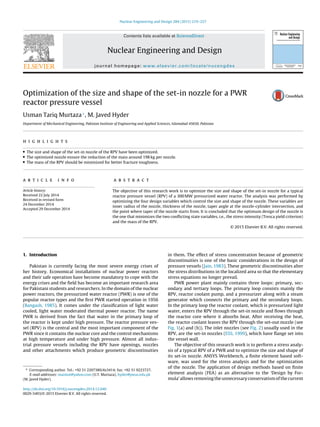
- 1. Nuclear Engineering and Design 284 (2015) 219–227 Contents lists available at ScienceDirect Nuclear Engineering and Design journal homepage: www.elsevier.com/locate/nucengdes Optimization of the size and shape of the set-in nozzle for a PWR reactor pressure vessel Usman Tariq Murtaza∗ , M. Javed Hyder Department of Mechanical Engineering, Pakistan Institute of Engineering and Applied Sciences, Islamabad 45650, Pakistan h i g h l i g h t s • The size and shape of the set-in nozzle of the RPV have been optimized. • The optimized nozzle ensure the reduction of the mass around 198 kg per nozzle. • The mass of the RPV should be minimized for better fracture toughness. a r t i c l e i n f o Article history: Received 22 July 2014 Received in revised form 24 December 2014 Accepted 29 December 2014 a b s t r a c t The objective of this research work is to optimize the size and shape of the set-in nozzle for a typical reactor pressure vessel (RPV) of a 300 MW pressurized water reactor. The analysis was performed by optimizing the four design variables which control the size and shape of the nozzle. These variables are inner radius of the nozzle, thickness of the nozzle, taper angle at the nozzle-cylinder intersection, and the point where taper of the nozzle starts from. It is concluded that the optimum design of the nozzle is the one that minimizes the two conflicting state variables, i.e., the stress intensity (Tresca yield criterion) and the mass of the RPV. © 2015 Elsevier B.V. All rights reserved. 1. Introduction Pakistan is currently facing the most severe energy crises of her history. Economical installations of nuclear power reactors and their safe operation have become mandatory to cope with the energy crises and the field has become an important research area for Pakistani students and researchers. In the domain of the nuclear power reactors, the pressurized water reactor (PWR) is one of the popular reactor types and the first PWR started operation in 1956 (Bangash, 1985). It comes under the classification of light water cooled, light water moderated thermal power reactor. The name PWR is derived from the fact that water in the primary loop of the reactor is kept under high pressure. The reactor pressure ves- sel (RPV) is the central and the most important component of the PWR since it contains the nuclear core and the control mechanisms at high temperature and under high pressure. Almost all indus- trial pressure vessels including the RPV have openings, nozzles and other attachments which produce geometric discontinuities ∗ Corresponding author. Tel.: +92 51 2207380/4x3414; fax: +92 51 9223727. E-mail addresses: maniiut@yahoo.com (U.T. Murtaza), hyder@pieas.edu.pk (M. Javed Hyder). in them. The effect of stress concentration because of geometric discontinuities is one of the basic considerations in the design of pressure vessels (Jain, 1983). These geometric discontinuities alter the stress distributions in the localized area so that the elementary stress equations no longer prevail. PWR power plant mainly contains three loops: primary, sec- ondary and tertiary loops. The primary loop consists mainly the RPV, reactor coolant pump, and a pressurizer along with a steam generator which connects the primary and the secondary loops. In the primary loop the reactor coolant, which is pressurized light water, enters the RPV through the set-in nozzle and flows through the reactor core where it absorbs heat. After receiving the heat, the reactor coolant leaves the RPV through the set-out nozzle (see Fig. 1(a) and (b)). The inlet nozzles (see Fig. 2) usually used in the RPV, are the set-in nozzles (ESS, 1999), which have flange set into the vessel wall. The objective of this research work is to perform a stress analy- sis of a typical RPV of a PWR and to optimize the size and shape of its set-in nozzle. ANSYS Workbench, a finite element based soft- ware, was used for the stress analysis and for the optimization of the nozzle. The application of design methods based on finite element analysis (FEA) as an alternative to the ‘Design by For- mula’ allows removing the unnecessary conservatism of the current http://dx.doi.org/10.1016/j.nucengdes.2014.12.040 0029-5493/© 2015 Elsevier B.V. All rights reserved.
- 2. 220 U.T. Murtaza, M. Javed Hyder / Nuclear Engineering and Design 284 (2015) 219–227 Fig. 1. Engineering drawing of the typical RPV (Haseeb, 2014). (a) Cut section view, dimensions in mm; (b) top view. design codes (Guerrero et al., 2008). FEA offers a great deal of promise over other approaches mainly experimental, in the sense of low cost, high speed, complete information, and ability to simu- late realistic and ideal conditions (Hyder and Asif, 2008). Using FEA, many researchers have performed the stress analysis (Adil, 2012; Khan, 2012) and fracture mechanics analysis (Chen et al., 2014; Murtaza and Hyder, 2014) of different parts of their RPVs which validate the use of FEA in this field. Traditionally, the design and manufacturing of the nuclear RPV’s are governed by the mandatory codes that ensure high safety performance. Most pressure vessel design codes, e.g. ASME code (ASME Boiler and Pressure Vessel Code, 2010b), EN13445 (European Committee for Standardization, 2002), BS550 (British Standards Institution, 1986), assume a membrane stress state con- dition for the determination of minimum shell thickness and apply large safety factors at areas of geometric discontinuities. It should be noted that large safety factors lead to increasing the mate- rial thickness, while the safety is not necessarily increased; that is fracture toughness decreases with increasing thickness (Broek, 1986; Dieter, 1987), and stress corrosion cracking at components operating in corrosive environments is expected to be higher in thicker parts (Diamantoudis and Kermanidis, 2005). To control the fracture toughness, the material thickness or mass of the compo- nent essentially needs to be minimized (Ramesh, 2007). In this study, the set-in nozzle is optimized such that it satisfies the con- servative Tresca yield criterion as well as the limitation of minimum mass of the RPV. In other words, the optimization is performed such that the nozzle has to fulfill two criterions (Tresca and minimum mass) instead of the single failure criterion. 2. Problem description Fig. 1 shows a typical double loop cylindrical RPV (Haseeb, 2014) of a 300 MW pressurized water reactor. Fig. 2(a) shows the typical set-in nozzle (hereinafter called ‘the nozzle’) used in the RPV. The design variables (see Fig. 2(b)) which control the size and shape of the nozzle are inner radius of the nozzle (R), thickness of the nozzle (tn), taper angle at the nozzle-cylinder intersection (Â), and the span (X) where taper of the nozzle starts from. The existing design of the nozzle has been optimized by changing the design variables such that it minimizes the stress intensity (Tresca yield criterion) and mass of the RPV as much as possible. The stress intensity and mass of the RPV are nominated as the state variables in this study. Fig. 2. Set-in nozzle. (a) Existing design in the RPV (Haseeb, 2014); (b) design variables of set-in nozzle.
- 3. U.T. Murtaza, M. Javed Hyder / Nuclear Engineering and Design 284 (2015) 219–227 221 Fig. 3. (a) Sweepable bodies in the RPV; (b) full 3D solid186 element mesh model; (c) close-up view of the set-in nozzle. 2.1. Boundary conditions The following boundary conditions (B.Cs) have been applied for the optimization of the nozzle. 1. Taking the advantage of the geometric and loading symmetry, as shown in Fig. 1(b), only half of the RPV is modeled for FEA. 2. The internal pressure of the RPV is equal to Pint = 17.16 MPa which is the design pressure (He and Isozaki, 2000) of the RPV. 3. The support pads of the RPV are fixed in the vertical direction while they are free to move in the radial and tangential directions of the vessel (see Fig. 1(b)). In ANSYS Workbench, frictionless support is applied on the lower faces of the RPV support pads. It prevents support from moving in the vertical direction of the RPV and allows it to freely move in the radial and tangential direc- tions of the RPV. The bending loads caused by the support pads on the nozzle have been considered in the analysis. The effects of axial loads have also been considered but they are negligible (Haseeb, 2014) as because the support pads are free to move in the axial direction of the nozzle (see Fig. 2). 2.2. Material properties The material selected for the RPV is SA-508 Gr.3 Cl.1 (He and Isozaki, 2000), a nuclear grade steel having nominal composition (3/4Ni–1/2Mo–Cr–V). The material properties used for the opti- mization of the nozzle have been given in Table 1. 2.3. Constraints on the design variables The main cylinder of the RPV and the location of the nozzle in the RPV are fixed (see Fig. 1(a)). It is due to the limitations imposed by internals of the RPV. The constraints applied on the design vari- ables for the optimization analysis have been listed in Table 2. To ensure the smooth passage of the required coolant flow from the nozzle, lower bound value of the inner radius (R) is same as the existing design value of the nozzle. The remaining design variables Table 1 Material properties (ASME Boiler and Pressure Vessel Code, 2010a). Density (kg/m3 ) Young’s modulus (GPa) Poisson’s ratio Tensile yield strength (MPa) Tensile ultimate strength (MPa) 7750 200 0.3 345 552 do not restrict the coolant flow rate and hence their lower and upper bound values have been selected by engineering judgment. 3. Finite element model of RPV A commercially available software, ANSYS Workbench, was utilized for modeling, meshing and FEA of the RPV. In ANSYS Workbench ‘DesignModeler’ is a module for CAD modeling while ‘Mechanical’ is a module for generating the mesh and perform- ing the FEA. Traditionally, a hexahedral mesh is computationally more efficient and preferable than the tetrahedral mesh. For creat- ing hexahedral mesh in a body, sweep mesh is one of the methods which may be utilized. By definition, a body can be swept into hexahedral mesh if it contains atleast a pair of topologically simi- lar faces. Topologically similar faces can simply be defined as two faces having equal number of vertices and essentially connected by a smooth path. Such faces are called the source and target faces in sweep mesh method. ANSYS Mechanical normally mesh the source face with quadrilateral elements and then copy that mesh onto the target face, resulting a hexahedral mesh in the body. For creating an all-hexahedral finite element (FE) model of the RPV, sweep mesh method was utilized in ANSYS Workbench. The RPV as one part structure does not fulfill the topological require- ments for sweeping and is therefore not amenable to hexahedral mesh. In order to make the RPV amenable for sweep mesh, slicing and dicing technique was utilized for the creation of the geometry. Using the technique the unsweepable RPV was decomposed into several sweepable bodies. Each sweepable body, having topologi- cally consistent source and target faces, is shown with a different color in Fig. 3(a). The sweepable multibody RPV was then glued togather to make a single part. The gluing is also compulsory to ensure consistent nodes at the connecting faces of the sweepable bodies. The sweep is the default ANSYS Mechanical meshing approach if the structure’s topology is recognized as sweepable. Once the Table 2 Constraints on the design variables. Design variable Lower bound value Existing design value Upper bound value R 354 mm 354 mm 425 mm tn 120 mm 171 mm 222 mm  1◦ 6◦ 9◦ X 425 mm 539.5 mm 900 mm
- 4. 222 U.T. Murtaza, M. Javed Hyder / Nuclear Engineering and Design 284 (2015) 219–227 Fig. 4. Hoop stress distribution, values in MPa. (a) Isometric view; (b) cut section view. prepared model of the RPV was transferred to the ANSYS Mechan- ical, the free mesher of the module has developed an efficient hexahedral mesh as shown in Fig. 3(b). The FE model of the RPV has the skewness equal to 0.851. The skewness, a mea- sure of mesh quality, ranges from 0 to 1, the smaller the better; and FE model having skewness less than 0.95 is acceptable for FEA (Lee, 2012). As the developed FE model has the skewness value less than 0.95, it is therefore an acceptable model for the analysis. The FE model shown in Fig. 3(b) contains a total of 89,642 finite elements and 238,091 nodes. The element type used for the stress analysis is Solid-186, which is a higher order 3-D, 20 node brick element with midside nodes and curved edges. 4. Results and discussions 4.1. Stress analysis of the existing set-in nozzle For the optimization of the existing design of the nozzle, a detailed numerical analysis was performed using the FE model pre- sented in Section 3. The existing design (see Fig. 2(a)) of the nozzle has dimensions R = 354 mm, tn = 171 mm,  = 6◦ and X = 539.5 mm. The hoop stress ( h) and stress intensity (S.I.) distributions along the whole nozzle are shown in Figs. 4 and 5 respectively. The maxi- mum stress intensity was calculated using Tresca yield criterion or maximum shear stress theory (Dieter, 1987; Shigley, 1986) which is given by Eq. (1). S.I. = h − r (1) According to Tresca yield criterion, the maximum stress inten- sity value (347.18 MPa) at the nozzle-cylinder intersection (see Fig. 5) predicts local yielding as it is greater than the yield strength of the (Sy = 345 MPa) of the material (see Table 1). The mass of the RPV with existing design of the nozzle is 96,551.0 kg. 4.2. Mesh independent study The basic mesh independent study was performed and a plot of maximum stress intensity versus number of nodes has been shown in Fig. 6. By increasing the number of nodes, an increasing trend in the maximum stress intensity is seen as shown in Fig. 6. It is evident from the curve that the solution becomes converged when the number of nodes reaches around 238,091. It is due to the fact that the FE model containing 238,091 number of nodes was selected for the optimization of the nozzle. 4.3. Stress analysis of the existing nozzle by varying the design variables The stress analysis of the existing nozzle by varying a single design variable (keeping other three variables constant) was per- formed and the results have been presented in Fig. 7. Fig. 7(a) shows the behavior of the maximum hoop, axial and radial stresses against the inner radius (R) of the nozzle while X, tn and  have been kept constant. It is evident from the graph that as radius of the nozzle increases the maximum hoop stress also increases. The axial and radial stresses remain almost constant with the increase of the inner radius. Fig. 5. Stress intensity, values in MPa. (a) Isometric view; (b) cut section view.
- 5. U.T. Murtaza, M. Javed Hyder / Nuclear Engineering and Design 284 (2015) 219–227 223 Fig. 6. Mesh independent study. Fig. 7(b) shows the behavior of the maximum hoop, axial and radial stresses against the thickness (tn) of the nozzle while R, X and  have been kept constant. It is evident from the graph that as the thickness of the nozzle increases, the hoop stress decreases. Fur- thermore, it is also noted that in the range of 120 mm < tn < 158 mm, decrease in the hoop stress is negligible. A relatively higher decrease in the hoop stress is noted when tn > 158 mm. The axial and radial stresses remain almost constant with the increase of the thickness. Fig. 7(c) shows the behavior of the maximum hoop, axial and radial stresses against the taper angle (Â) of the nozzle while R, X and tn have been kept constant. An increase in the hoop stress is noted up to  = 6.33◦ while it decreases slightly when  > 6.33◦. The axial and radial stresses remain almost constant with the increase of taper angle. Fig. 7(d) shows the behavior of the maximum hoop, axial and radial stresses against the span (X) while R, tn and  have been kept constant. An increase in the hoop stress is noted up to X = 504 mm while it decreases when X > 504 mm. The axial and radial stresses remain almost constant with the increase of the span. 4.4. The design variables against the state variables The effects of changing a single design variable (keeping other three variables constant) on the state variables (stress intensity and mass of the RPV) were also investigated and have been presented in Fig. 8. Fig. 8(a) shows the behavior of the maximum stress intensity and the mass of the RPV against the inner radius (R) of the noz- zle while X, tn and  have been kept constant. It is evident from the graph that with the increase of inner radius, stress intensity increases while mass of the RPV decreases. Fig. 8(b) shows the behavior of the maximum stress intensity and the mass of the RPV against the thickness (tn) of the nozzle Fig. 7. Maximum hoop, axial and radial stresses along the nozzle against the design variables.
- 6. 224 U.T. Murtaza, M. Javed Hyder / Nuclear Engineering and Design 284 (2015) 219–227 Fig. 8. Behavior of the stress intensity and the mass of the RPV against the design variables. while R, X, and  have been kept constant. It is evident from the graph that with the increase of the nozzle thickness, the mass of the RPV increases. On the other hand, the stress intensity increases slightly in the range of 120 mm < tn < 141.2 mm while it decreases when tn > 141.2 mm. Fig. 8(c) shows the behavior of the maximum stress intensity and the mass of the RPV against the taper angle (Â) while R, X, and tn have been kept constant. It is evident from the graph that the mass of the RPV decreases linearly with the increase of the taper angle. On the other hand, the stress intensity increases up to  = 6.0◦, while it decreases when  > 6.0◦. Fig. 8(d) shows the behavior of the maximum stress intensity and the mass of the RPV against the span (X) where R, tn and  have been kept constant. It is evident from the graph that the mass of the RPV increases with the increase of the span. On the other hand the stress intensity increases up to X = 504 mm, while it decreases when X > 504 mm. It is evident from Fig. 8 that the two state variables conflict with each other and an optimized design with respect to a single objective (minimizing the stress intensity) leads to an unacceptable results with respect to the other objective (minimizing the mass of the RPV). The discussion finally leads to the fact that an opti- mum value of the design variables needs to be investigated which ensures the minimization of the two conflicting state variables. It is a multi-objective problem as the objective is to minimize the stress intensity as well as the mass of the RPV. 4.5. Optimization For investigating an optimum design of the nozzle, simulations with several design points were performed. The design points were chosen according to a method of design of experiments (Lee, 2012). The 26 design points (including the existing design of the noz- zle) along with the state variables have been given in Table 3 and in Fig. 9. With these design points it is possible to construct the response surfaces of full 2nd order polynomials. In order to search the constructed response surfaces for the optimized points, genetic algorithm (GA) based multi-objective optimization was performed. GA is a robust optimization algorithm and a wide class of problems can be solved using GA. It is one of the global optimization tech- niques and does ensure the convergence to the global optimum (Deb, 2001). Fig. 9. The state variables against the design points.
- 7. U.T. Murtaza, M. Javed Hyder / Nuclear Engineering and Design 284 (2015) 219–227 225 Table 3 Design of experiment. Design points R (mm) tn (mm)  (Deg) X (mm) Max. S.I. (MPa) RPV mass (kg) 1 (Existing design point) 354.0 171.0 6.0 539.5 347.18 96,551.0 2 389.5 171.0 5.0 662.5 360.52 96,542.5 3 364.5 135.1 2.2 495.3 356.78 96,345.0 4 364.5 135.1 2.2 829.7 329.72 96,436.9 5 364.5 206.9 2.2 495.3 347.25 97,008.5 6 364.5 206.9 2.2 829.7 320.58 97,100.4 7 364.5 135.1 7.8 495.3 360.39 96,032.7 8 364.5 135.1 7.8 829.7 326.47 96,387.6 9 364.5 206.9 7.8 495.3 350.77 96696.2 10 364.5 206.9 7.8 829.7 317.07 97,051.2 11 414.5 135.1 2.2 495.3 386.72 96,090.6 12 414.5 135.1 2.2 829.7 356.13 96,196.4 13 389.5 171.0 5.0 425.0 371.49 96,323.8 14 414.5 206.9 2.2 495.3 374.48 96,826.1 15 414.5 206.9 2.2 829.7 345.10 96,932.0 16 414.5 135.1 7.8 495.3 392.88 95,729.9 17 414.5 135.1 7.8 829.7 350.89 96137.4 18 414.5 206.9 7.8 495.3 380.02 96,465.4 19 414.5 206.9 7.8 829.7 338.75 96,872.9 20 389.5 171.0 5.0 900.0 338.64 96,657.9 21 389.5 120.0 5.0 662.5 368.47 96,071.0 22 389.5 222.0 5.0 662.5 352.62 97,064.1 23 389.5 171.0 1.0 662.5 364.74 96,653.9 24 389.5 171.0 9.0 662.5 358.14 96,421.9 25 354.0 171.0 5.0 662.5 342.28 96,687.3 26 425.0 171.0 5.0 662.5 382.77 96,370.3 The optimization using multi-objective genetic algorithm (MOGA) can be performed in ANSYS workbench (ANSYS Inc., 2014). MOGA is based on the controlled elitism concepts and can be used to ensure the minimization of the two state variables (the stress intensity and the mass of the RPV). It supports multiple objectives and constraints and aims at finding the global optimum. Generally, it works with the coding of the parameter set, not the parameters themselves. In the process, the values of the design variables R, X, tn and  will be replaced into their binary equivalents. The MOGA searches for a population of points, not a single point. It converts the 0’s and 1’s of the binary equivalent into bits then mutates and crossovers the bits to produce children who then become parents. There is a strategy involved in MOGA that only the fittest can survive and form new generation (Deb, 2001). The simulations, using MOGA, in ANSYS workbench require the pre-defined values of the parameters: population size, crossover probability, mutation probability, and number of generations. The population size must be greater than or equal to the number of design variables (R, X, tn, Â). The minimum recommended number is Fig. 10. The state variables against the optimized points. 10 times the number of design variables; the larger the population size is, the better are the chances of finding the design space that contains the best solution (ANSYS Inc., 2014). The population size of 100 samples was used in this study. The crossover combines two chromosomes (parents) to pro- duce a new chromosome (children). The idea behind crossover is that the new chromosome may be better than both of the parents if it takes the best characteristics from each of the par- ents. The value of the crossover probability must be within 0 and 1. A smaller value indicates a more stable population and a faster (but less accurate) solution; the parents are copied directly to the new population if the value is 0. A high prob- ability of crossover (>0.9) is recommended (ANSYS Inc., 2014); Fig. 11. The proposed optimized set-in nozzle for the RPV.
- 8. 226 U.T. Murtaza, M. Javed Hyder / Nuclear Engineering and Design 284 (2015) 219–227 Table 4 Optimized points versus the state variables. Optimized points R (mm) tn (mm) Â (Deg) X (mm) Max. S.I. (MPa) RPV mass (kg) 1 355.7 121.8 8.9 882.8 310.48 96,353.0 2 360.3 122.9 8.9 836.1 318.04 96,305.0 therefore, a crossover probability equal to 0.98 was used in this study. Mutation alters one or more gene values in a chromosome from its initial state. This can result in entirely new gene values being added to the gene pool. With these new gene values, the GA may be able to arrive at a better solution than was previously possi- ble. Mutation is an important part of the genetic search, as it helps to prevent the population from stagnating at any local optima. The value of the mutation probability must be between 0 and 1. A larger value indicates a more random algorithm; the algorithm becomes the pure random search if the value is 1. A low probability of mutation (<0.2) is recommended (ANSYS Inc., 2014); therefore, a mutation probability equal to 0.01 was used in this study. The number of generations is the maximum number of itera- tions which algorithm executes. If the number of iterations reaches the maximum number of iterations before the optimization attains convergence, iteration will stop. The maximum number of gener- ations equal to 20 was used in this study. Finally, using MOGA, the constructed response surfaces were searched for the optimized points and two candidate points have been investigated which are provided in Table 4 and in Fig. 10. The optimized points ensure minimum possible values of the two conflicting state variables as evident from Fig. 10. Further- more, the optimized point no.1 results minimum stress intensity (310.48 MPa) at the nozzle-cylinder intersection and a huge reduc- tion of the mass of the RPV. The mass of the RPV with the optimized nozzle is reduced to 96,353.0 kg. The reduction of the mass is about 198 kg per nozzle which finally leads to an economical design reducing the material and manufacturing cost. The proposed optimized design of the nozzle has the dimen- sions R = 355.72 mm, tn = 121.8 mm, Â = 8.90◦ and X = 882.79 mm. The engineering drawing of the proposed nozzle for the RPV is given in Fig. 11. 4.6. Stress analysis of the optimized nozzle The stress analysis of the optimized nozzle was also performed and the results have been presented in this section. The hoop stress distributions and the stress intensity along the optimized nozzle have been shown in Figs. 12 and 13 respectively. It is evident from Fig. 13 that according to Tresca yield crite- rion, the stress intensity values do not predict yielding at any point Fig. 12. Hoop stress distribution. (a) Isometric view; (b) cut section view. Fig. 13. Stress intensity. (a) Isometric view; (b) cut section view.
- 9. U.T. Murtaza, M. Javed Hyder / Nuclear Engineering and Design 284 (2015) 219–227 227 of the optimized nozzle. Clearly, the maximum stress intensity (310.48 MPa) is lower than the yield strength (Sy = 345 MPa) of the material (see Table 1). In addition to this, as the fracture toughness of the nozzle is the function of the nozzle thickness (Broek, 1986; Dieter, 1987), the maximum fracture toughness can be achieved by reducing the nozzle thickness up to 121.80 mm. 5. Conclusions In this paper we have optimized the size and shape of the set-in nozzle for an RPV using finite element analysis. The design of the nozzle depends on the four variables, which are inner radius of the nozzle, thickness of the nozzle, taper angle at the nozzle-cylinder intersection and the point where taper of the nozzle starts from. It has been shown that the two state variables (the stress intensity and the mass of the RPV) conflict with each other. For a safe design, it is evidently required to reduce the stress intensity along the nozzle below the yield strength of the material. Furthermore, to achieve the maximum fracture toughness of the RPV, its mass should be minimized as much as possible. The proposed optimized nozzle ensures the maximum stress intensity below the yield strength of the material and the reduction in the mass of the RPV about 198 kg per nozzle. Acknowledgement The financial support of Pakistan Institute of Engineering and Applied Sciences for this research work, under IT & Telecom Endow- ment Fund, is gratefully acknowledged. References Adil, M., M.S. Dissertation 2012. Structural Analysis of Typical PWR Pressure Vessel (Effect of Cylindrical Thickness). Pakistan Institute of Engineering and Applied Sciences. ANSYS Inc., 2014. Design Exploration User’s Guide. ASME Boiler and Pressure Vessel Code, Section II, Part D: Properties, Materials, New York, 2010a. ASME Boiler and Pressure Vessel Code, Section III, Division 1: Rules for Construction Of Nuclear Facility Components, New York, 2010b. Bangash, Y., 1985. PWR steel pressure vessel design and practice. Prog. Nucl. Energy 16 (1), 1–40. British Standards Institution, 1986. Unfired Fusion Welded Pressure Vessels. Broek, D., 1986. Elementary Engineering Fracture Mechanics, 4th revised ed. Kluwer Academic Publishers, Dordrecht. Chen, M., Lu, F., Wang, R., Ren, A., 2014. Structural integrity assessment of the reactor pressure vessel under the pressurized thermal shock loading. Nucl. Eng. Des. 272, 84–91. Deb, K., 2001. Multi-objective Optimization Using Evolutionary Algorithms, 1st ed. John Wiley & Sons, Chichester. Diamantoudis, A.T., Kermanidis, T., 2005. Design by analysis versus design by for- mula of high strength steel pressure vessels: a comparative study. Int. J. Pres. Ves. Pip. 82, 43–50. Dieter, G.E., 1987. Mechanical Metallurgy, 3rd ed. McGraw-Hill, USA. ESS, 1999. Assessment and Management of Ageing of Major Nuclear Power Plant Components Important to Safety: PWR Pressure Vessels. European Committee for Standardization, EN 13445, Unfired Pressure Vessels – Part 3: Design, 2002. Guerrero, M.A., Betegon, C., Belzunce, J., 2008. Fracture analysis of a pressure vessel made of high strength steel (HSS). Eng. Fail. Anal. 15, 208–219. Haseeb, M., M.S. Dissertation 2014. Pressure Vessel Inlet Nozzle Strength Analysis Using ANSYS. Pakistan Institute of Engineering and Applied Sciences. He, Y., Isozaki, T., 2000. Fracture mechanics analysis and evaluation for the RPV of the Chinese Qinshan 300 MW NPP under PTS. Nucl. Eng. Des. 201, 121–137. Hyder, M.J., Asif, M., 2008. Optimization of location and size of opening in a pressure vessel cylinder using ANSYS. Eng. Fail. Anal. 15, 1–19. Jain, R.K., 1983. Machine Design, 3rd ed. Khanna Publications, Delhi. Khan, A., M. S. Dissertation 2012. Structural Analysis of PWR Pressure Vessel (Effect of Opening). Pakistan Institute of Engineering and Applied Sciences. Lee, H.H., 2012. Finite Element Simulations with ANSYS Workbench 14. Stephen Schroff, USA. Murtaza, U.T., Hyder, M.J., 2014. The effects of thermal stresses on the elliptical sur- face cracks in PWR reactor pressure vessel. Theor. Appl. Fract. Mech., http://dx. doi.org/10.1016/j.tafmec.2014.12.001. Ramesh, K., 2007. E-Book on Engineering Fracture Mechanics. IIT Madras, India. Shigley, J.E., 1986. Mechanical Engineering Design, 1st ed. McGraw-Hill, Singapore.