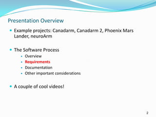
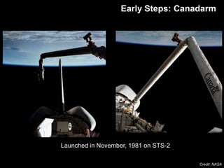
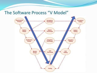
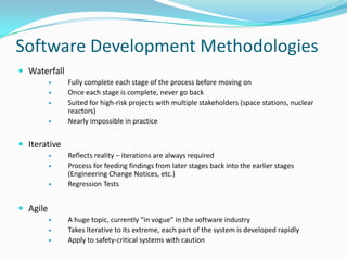
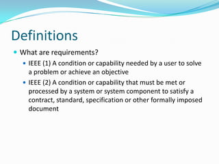
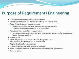
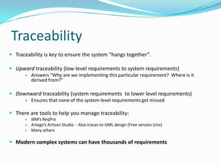
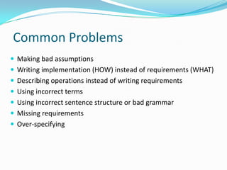
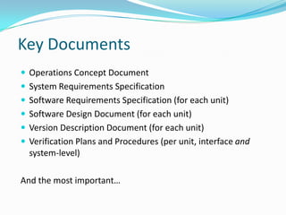
University of Waterloo, SYDE 161 Guest Lecture
October 5, 2011
Leif Bloomquist P.Eng (SYDE ‘97)
Senior Software Systems Engineer, Space Missions
Presentation Overview
 Example projects: Canadarm, Canadarm 2, Phoenix Mars
Lander, neuroArm
 The Software Process
 Overview
 Requirements
 Documentation
 Other important considerations
 A couple of cool videos!
2
September 14, 2013 3
Early Steps: Canadarm
Credit: NASA
Launched in November, 1981 on STS-2
 Power Usage
 Max 1,000 watts plus 1,050
watts of heater power
 Typically less than 300
watts, or 5 light bulbs.
 Construction
 Aluminum, stainless
steel, carbon composite.
 Thermal
 Thermostat controlled
electric heaters and thermal
blankets
 Payload handling
 266,000 kg (a fully loaded
Shuttle vehicle)
4September 14, 2013
Hubble = 11,100kg
September 14, 2013 5
Translational Hand Controller
(THC):
Right, up, down, forward, and
backward movements of the arm
Rotational Hand
Controller (RHC)
Controls the
pitch, roll, and yaw of
the arm
Canadarm2 Arrives (2001)
 17.6m long
 7 joints
 Mass: 1,800kg
 Handling Capacity: 100,000kg
 2 latching end effectors (“hands”)
 Force-moment sensing capability
 Relocatable – can travel end-over-end
 Electrically redundant
 On-orbit or Ground-based control
 PP: 2kW | Prms: 1360W
6September 14, 2013
Credit: NASA
Canadarm 2
Space Station Assembly
September 14, 2013 7Credit: NASA
Robotic Work Station aboard ISS
Dextre
 3.5 m (12 ft) long
 Two manipulator arms, each
with 7 joints
 One body roll joint
 Each arm fitted with an
Orbit Replacement
Unit/Tool Change-out
Mechanism (OTCM)
 Force-Moment sensing
capability
 600 kg (1300 lbs) payload
handling capacity
 One Latching End Effector
 Four special tools, carried in
Tool Holder 8September 14, 2013Credit: NASA
Phoenix MET
9
• Launched in August 2007
• Lands on Mars on May 25, 2008
• Meteorological station to assess the interaction of
surface ice with the atmosphere
– Zenith-pointing LiDAR to characterize Martian climate
and atmosphere (cloud, fog and dust properties)
– Temperature and pressure sensors
Phoenix Mars Lander
Snow on Mars
"You cannot study a surface and an ice layer without knowing the atmosphere above it, and we have a huge volume of data
that describes weather for the entire time we conducted surface operations," Smith said. "This is one of the major
accomplishments of the mission." At the end of the surface mission, Phoenix saw, for the first time, water as snow falling to
the surface Mars and frost on the ground. Falling snow was a real surprise – Peter Smith, Phoenix PI
But the really amazing data came from the LIDAR instrument… In short, they
watched it snow. (Timmer, Ars Technica July 2009)
neuroArm
Image guided robot operates inside of 1.5T
MRI for Intra-operative imaging and guidance
Successful procedures performed on patients
at Calgary Foothills Hospital
Performance Goals achieved:
• 15 Hz closed loop bandwidth for immersive
control – no delay or overshoot
• 50 micron tip position control
• Haptic feedback – 2g force sensing
• 1mm tool to image registration accuracy
How do these
critical, complex systems
come together?
The Software Process
 The aerospace industry generally follows MIL-STD-498 as a guideline for its
software process and documentation.
 United States military standard whose purpose was to "establish uniform
requirements for software development and documentation." It was
released Nov. 8, 1994
 Each company has its own customizations.
 The process is tailored per project, with customer approval.
 Superceded by IEEE 12207.0 "Standard for Information Technology –
Software Life Cycle Processes “ in 1998, but many organizations have kept
with the older format.
The Software Process
1. Develop an operations concept
 High level, what does the system need to do and how will it work?
 High-level use cases
2. Develop System requirements
 What will the System be expected to do?
3. Derive and allocate subsystem requirements
 Begin to establish detail, what parts will cover each function?
 Requires an initial system architecture concept
The Software Process
4. Derive detailed requirements for each discipline
(software, mechanical, electrical)
 More detailed use cases
 These are actually implementable and testable
5. Design a system that meets these requirements
 For software: Unified Modeling Language
 Prototyping and documentation
 Interfaces
6. Implement – Write your code (manufacture the part, etc…)
 If the previous steps were done satisfactorily – this can be the shortest
phase.
The Software Process
7. Validate and Verify (“Test”)
 Test to the requirements – not the design
 Start at lowest level and work your way up (next slide)
 Verification vs. validation
8. Release and Maintain
 See upcoming section on documentation
9. Iterate as necessary
 See upcoming section on development methodologies
Customer reviews and milestones at each step
The Software Process “V Model”
Software Development Methodologies
 Waterfall
 Fully complete each stage of the process before moving on
 Once each stage is complete, never go back
 Suited for high-risk projects with multiple stakeholders (space stations, nuclear
reactors)
 Nearly impossible in practice
 Iterative
 Reflects reality – iterations are always required
 Process for feeding findings from later stages back into the earlier stages
(Engineering Change Notices, etc.)
 Regression Tests
 Agile
 A huge topic, currently “in vogue” in the software industry
 Takes Iterative to its extreme, each part of the system is developed rapidly
 Apply to safety-critical systems with caution
Definitions
 What are requirements?
 IEEE (1) A condition or capability needed by a user to solve
a problem or achieve an objective
 IEEE (2) A condition or capability that must be met or
processed by a system or system component to satisfy a
contract, standard, specification or other formally imposed
document
Purpose of Requirements Engineering
 To achieve agreement on what is to be produced
 To decrease ambiguity and increase consistency and completeness
 To do this, understand the customer need
 If you do not understand what the customer wants you will fail
 Seek first to understand and then to be understood
 To document the agreed set of requirements
 It is not enough just to understand what the customer wants, it is also necessary to
record the understanding
 Shared vision
 To identify key issues: requirements with strong influence on
cost, schedule, functionality, risk or performance
 To provide a basis for system design
 To provide a reference point for system validation
 What if there are problems in the customer provided system specification?
 Communication
Benefits of Good Requirements
 Agreement among engineers, customers and users on the job
to be done and the acceptance criteria of the delivered system
 A sound basis for resource estimation
 Improved system effectiveness factors
 What if the customer does not specify these?
 The achievement of goals with minimum resources (less
rework, fewer omissions and misunderstandings)
 Reduced “expectation gap”
Problems with Bad Requirements
 Creeping user requirements
 Unplanned requirement changes degrades quality
 Ambiguous requirements lead to ill-spent time
 Increases expectation gap
 Customer and engineer have different opinions
 Needs of user are overlooked
 Fuzzy requirements make planning difficult
 The product may not be fit for use
 Can (will) lead to cost and schedule overruns
Why is it hard to write good requirements?
 Lack of knowledge that good system requirements are essential to the
development of a good system
 They are difficult to write: sophisticated problem solving is required to
produce a good statement of requirements
 Engineers lack training in requirements engineering
 It is next to impossible to capture user needs completely
 Desire to truncate the activity and “progress” to the next activity: schedule
pressure
 Customer failure to cooperate in effectively verifying that the requirements
are correct
 Assumptions are made which are not documented or discussed
 “How” instead of “What” is written
 We don’t pay attention to lessons learned
Requirement Attributes
 Good requirements have the following attributes:
 Necessary
 Unambiguous
 Complete
 Verifiable/Testable
 Consistent
 Maintainable
 Correct
 Implementation-free
 Concise
 Feasible
 Understandable
 Traceable
 Let’s try an example
Traceability
 Traceability is key to ensure the system “hangs together”.
 Upward traceability (low-level requirements to system requirements)
 Answers “Why are we implementing this particular requirement? Where is it
derived from?”
 Downward traceability (system requirements to lower level requirements)
 Ensures that none of the system-level requirements get missed
 There are tools to help you manage traceability:
 IBM’s ReqPro
 Artego’s Artisan Studio - Also traces to UML design (Free version Uno)
 Many others
 Modern complex systems can have thousands of requirements
Verbiage
 “Shall” indicates a mandatory requirement
 “Should” indicates a preferred but not mandatory alternative
 “May” indicates an option
 “Will” indicates a statement of intention or fact
These are often contractual
Common Problems
 Making bad assumptions
 Writing implementation (HOW) instead of requirements (WHAT)
 Describing operations instead of writing requirements
 Using incorrect terms
 Using incorrect sentence structure or bad grammar
 Missing requirements
 Over-specifying
Key Documents
 Operations Concept Document
 System Requirements Specification
 Software Requirements Specification (for each unit)
 Software Design Document (for each unit)
 Version Description Document (for each unit)
 Verification Plans and Procedures (per unit, interface and
system-level)
And the most important…
Interface Control Document
 Details of the interface between two entities
(subsystems, computers, devices, organizations…)
 Roles and responsibilities of all parties
 Can be data, mechanical, electrical, organizational…
Entity A Entity BInterface
Importance of ICDs
But when it all comes
together…
September 14, 2013 32
Questions?

Software Requirements and Design Process in the Aerospace Industry

  • 1.
    University of Waterloo,SYDE 161 Guest Lecture October 5, 2011 Leif Bloomquist P.Eng (SYDE ‘97) Senior Software Systems Engineer, Space Missions
  • 2.
    Presentation Overview  Exampleprojects: Canadarm, Canadarm 2, Phoenix Mars Lander, neuroArm  The Software Process  Overview  Requirements  Documentation  Other important considerations  A couple of cool videos! 2
  • 3.
    September 14, 20133 Early Steps: Canadarm Credit: NASA Launched in November, 1981 on STS-2
  • 4.
     Power Usage Max 1,000 watts plus 1,050 watts of heater power  Typically less than 300 watts, or 5 light bulbs.  Construction  Aluminum, stainless steel, carbon composite.  Thermal  Thermostat controlled electric heaters and thermal blankets  Payload handling  266,000 kg (a fully loaded Shuttle vehicle) 4September 14, 2013 Hubble = 11,100kg
  • 5.
    September 14, 20135 Translational Hand Controller (THC): Right, up, down, forward, and backward movements of the arm Rotational Hand Controller (RHC) Controls the pitch, roll, and yaw of the arm
  • 6.
    Canadarm2 Arrives (2001) 17.6m long  7 joints  Mass: 1,800kg  Handling Capacity: 100,000kg  2 latching end effectors (“hands”)  Force-moment sensing capability  Relocatable – can travel end-over-end  Electrically redundant  On-orbit or Ground-based control  PP: 2kW | Prms: 1360W 6September 14, 2013 Credit: NASA Canadarm 2
  • 7.
    Space Station Assembly September14, 2013 7Credit: NASA Robotic Work Station aboard ISS
  • 8.
    Dextre  3.5 m(12 ft) long  Two manipulator arms, each with 7 joints  One body roll joint  Each arm fitted with an Orbit Replacement Unit/Tool Change-out Mechanism (OTCM)  Force-Moment sensing capability  600 kg (1300 lbs) payload handling capacity  One Latching End Effector  Four special tools, carried in Tool Holder 8September 14, 2013Credit: NASA
  • 9.
    Phoenix MET 9 • Launchedin August 2007 • Lands on Mars on May 25, 2008 • Meteorological station to assess the interaction of surface ice with the atmosphere – Zenith-pointing LiDAR to characterize Martian climate and atmosphere (cloud, fog and dust properties) – Temperature and pressure sensors Phoenix Mars Lander
  • 10.
    Snow on Mars "Youcannot study a surface and an ice layer without knowing the atmosphere above it, and we have a huge volume of data that describes weather for the entire time we conducted surface operations," Smith said. "This is one of the major accomplishments of the mission." At the end of the surface mission, Phoenix saw, for the first time, water as snow falling to the surface Mars and frost on the ground. Falling snow was a real surprise – Peter Smith, Phoenix PI But the really amazing data came from the LIDAR instrument… In short, they watched it snow. (Timmer, Ars Technica July 2009)
  • 11.
    neuroArm Image guided robotoperates inside of 1.5T MRI for Intra-operative imaging and guidance Successful procedures performed on patients at Calgary Foothills Hospital Performance Goals achieved: • 15 Hz closed loop bandwidth for immersive control – no delay or overshoot • 50 micron tip position control • Haptic feedback – 2g force sensing • 1mm tool to image registration accuracy
  • 12.
    How do these critical,complex systems come together?
  • 13.
    The Software Process The aerospace industry generally follows MIL-STD-498 as a guideline for its software process and documentation.  United States military standard whose purpose was to "establish uniform requirements for software development and documentation." It was released Nov. 8, 1994  Each company has its own customizations.  The process is tailored per project, with customer approval.  Superceded by IEEE 12207.0 "Standard for Information Technology – Software Life Cycle Processes “ in 1998, but many organizations have kept with the older format.
  • 14.
    The Software Process 1.Develop an operations concept  High level, what does the system need to do and how will it work?  High-level use cases 2. Develop System requirements  What will the System be expected to do? 3. Derive and allocate subsystem requirements  Begin to establish detail, what parts will cover each function?  Requires an initial system architecture concept
  • 15.
    The Software Process 4.Derive detailed requirements for each discipline (software, mechanical, electrical)  More detailed use cases  These are actually implementable and testable 5. Design a system that meets these requirements  For software: Unified Modeling Language  Prototyping and documentation  Interfaces 6. Implement – Write your code (manufacture the part, etc…)  If the previous steps were done satisfactorily – this can be the shortest phase.
  • 16.
    The Software Process 7.Validate and Verify (“Test”)  Test to the requirements – not the design  Start at lowest level and work your way up (next slide)  Verification vs. validation 8. Release and Maintain  See upcoming section on documentation 9. Iterate as necessary  See upcoming section on development methodologies Customer reviews and milestones at each step
  • 17.
    The Software Process“V Model”
  • 18.
    Software Development Methodologies Waterfall  Fully complete each stage of the process before moving on  Once each stage is complete, never go back  Suited for high-risk projects with multiple stakeholders (space stations, nuclear reactors)  Nearly impossible in practice  Iterative  Reflects reality – iterations are always required  Process for feeding findings from later stages back into the earlier stages (Engineering Change Notices, etc.)  Regression Tests  Agile  A huge topic, currently “in vogue” in the software industry  Takes Iterative to its extreme, each part of the system is developed rapidly  Apply to safety-critical systems with caution
  • 19.
    Definitions  What arerequirements?  IEEE (1) A condition or capability needed by a user to solve a problem or achieve an objective  IEEE (2) A condition or capability that must be met or processed by a system or system component to satisfy a contract, standard, specification or other formally imposed document
  • 20.
    Purpose of RequirementsEngineering  To achieve agreement on what is to be produced  To decrease ambiguity and increase consistency and completeness  To do this, understand the customer need  If you do not understand what the customer wants you will fail  Seek first to understand and then to be understood  To document the agreed set of requirements  It is not enough just to understand what the customer wants, it is also necessary to record the understanding  Shared vision  To identify key issues: requirements with strong influence on cost, schedule, functionality, risk or performance  To provide a basis for system design  To provide a reference point for system validation  What if there are problems in the customer provided system specification?  Communication
  • 21.
    Benefits of GoodRequirements  Agreement among engineers, customers and users on the job to be done and the acceptance criteria of the delivered system  A sound basis for resource estimation  Improved system effectiveness factors  What if the customer does not specify these?  The achievement of goals with minimum resources (less rework, fewer omissions and misunderstandings)  Reduced “expectation gap”
  • 22.
    Problems with BadRequirements  Creeping user requirements  Unplanned requirement changes degrades quality  Ambiguous requirements lead to ill-spent time  Increases expectation gap  Customer and engineer have different opinions  Needs of user are overlooked  Fuzzy requirements make planning difficult  The product may not be fit for use  Can (will) lead to cost and schedule overruns
  • 23.
    Why is ithard to write good requirements?  Lack of knowledge that good system requirements are essential to the development of a good system  They are difficult to write: sophisticated problem solving is required to produce a good statement of requirements  Engineers lack training in requirements engineering  It is next to impossible to capture user needs completely  Desire to truncate the activity and “progress” to the next activity: schedule pressure  Customer failure to cooperate in effectively verifying that the requirements are correct  Assumptions are made which are not documented or discussed  “How” instead of “What” is written  We don’t pay attention to lessons learned
  • 24.
    Requirement Attributes  Goodrequirements have the following attributes:  Necessary  Unambiguous  Complete  Verifiable/Testable  Consistent  Maintainable  Correct  Implementation-free  Concise  Feasible  Understandable  Traceable  Let’s try an example
  • 25.
    Traceability  Traceability iskey to ensure the system “hangs together”.  Upward traceability (low-level requirements to system requirements)  Answers “Why are we implementing this particular requirement? Where is it derived from?”  Downward traceability (system requirements to lower level requirements)  Ensures that none of the system-level requirements get missed  There are tools to help you manage traceability:  IBM’s ReqPro  Artego’s Artisan Studio - Also traces to UML design (Free version Uno)  Many others  Modern complex systems can have thousands of requirements
  • 26.
    Verbiage  “Shall” indicatesa mandatory requirement  “Should” indicates a preferred but not mandatory alternative  “May” indicates an option  “Will” indicates a statement of intention or fact These are often contractual
  • 27.
    Common Problems  Makingbad assumptions  Writing implementation (HOW) instead of requirements (WHAT)  Describing operations instead of writing requirements  Using incorrect terms  Using incorrect sentence structure or bad grammar  Missing requirements  Over-specifying
  • 28.
    Key Documents  OperationsConcept Document  System Requirements Specification  Software Requirements Specification (for each unit)  Software Design Document (for each unit)  Version Description Document (for each unit)  Verification Plans and Procedures (per unit, interface and system-level) And the most important…
  • 29.
    Interface Control Document Details of the interface between two entities (subsystems, computers, devices, organizations…)  Roles and responsibilities of all parties  Can be data, mechanical, electrical, organizational… Entity A Entity BInterface
  • 30.
  • 31.
    But when itall comes together…
  • 32.
  • 33.