
Recommended
More Related Content
What's hot
What's hot (18)
Similar to Pisa brochure
Similar to Pisa brochure (20)
More from kristenjames
More from kristenjames (20)
Recently uploaded
Recently uploaded (20)
Pisa brochure
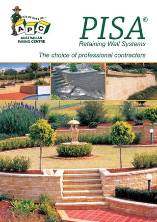
- 1. PISA Retaining Wall Systems The choice of professional contractors
- 2. DESCRIPTION & DIMENSIONS (H x W x D) ~ WEIGHT PER UNIT 5501 Light Vertical Straight Unit 150 x 200 x 220 9.5 5502 Light Vertical Tapered Unit 150 x 200 x 220 5131 No./ Lin M² UNITS PER PALLET 33 5 132 9.0 33 5 132 Left Hand Corner 150 x 300 x 200 18.0 - - 48 L/H & 48 R/H 5132 Right Hand Corner 150 x 300 x 200 18.0 - - 48 L/H & 48 R/H 5440 440 Capping Unit 65 x 440 x 320 16.0 - 2.3 84 5103 PRODUCT 200 Capping Unit (Check Availability) 65 x 200 x 230 5.3 - 5 270 CODE No./M² Advantages • Won’t rot like a wooden sleeper wall • Virtually maintenance free • No mortar required • Ability to construct the wall yourself with no previous experience • No pins needed • Self aligning • No concrete footing required • Ability to easily make steps. Internal and external to wall • Flexible system won’t crack like a brick wall • Range of capping units to suit your job
- 3. Colour range Autumn Gold Ivory Bluestone Charlestone Desert Sand NOTE: These colours are an indication only, please contact your nearest distributor to view sample colours.
- 4. Corners External Left Curves Steps Concave Curve Right Convex Curve • Use left and right cornerstones alternately Internal 1st Course 2nd Course (and 3rd, 5th & 7th…) (and 4th, 6th & 8th…) • Using straight PISA units you can create internal corners with the method detailed above. • To create a convex curve use tapered units. Use Left tapered units on one course, right tapered units on the next, alternating up the wall. • To create a concave wall use straight units. • Minimum radius: 2400mm (Add 20mm to this for each course in the wall) • Steps are easily created with Pisa by simply using standard units for risers and split face capping units for step treads. • You can create internal or external stairs to your wall. • Ask your Pisa salesperson for a Pisa Stair construction help sheet.
- 5. PISA Height Tables ® Walls up to 600mm in height Unreinforced retaining wall MAXIMUM HEIGHT ACHIEVABLE (mm) Hollow Block Footing Thickness (mm) Footing Width (mm) Footing Toe (mm) 200 600 250 600 The wall height shown above applies for average soil conditions (Friction Angle>20° and cohesion factor > 5kPa). There must be no surcharge (ie no applied load or backfill slope > 1:4) Top Soil Undisturbed Soil Geo-textile Cloth Distance to Footing Toe Drainage layer of 12 mm angular clear stone Compacted sand or mortar bed layer Drain >90mm Footing Thickness Compacted crushed Rock levelling footing Footing Width Walls over one metre in height (Engineer design required) *Note: These tables are indicative only. All walls over 1000mm in height must be designed and certified by an engineer. Geo-grid reinforced wall No-fines concrete constructed wall No-fines concrete. Depth determined by table. Top Soil Top Soil Undisturbed Soil Geo-textile Cloth Distance to Footing Toe Undisturbed Soil Geo-textile Cloth Compacted select in fill area Compacted sand or mortar bed layer Perforated Drain >90mm Compacted crushed Rock levelling footing Footing Thickness Footing Width Distance to Footing Toe Geo-grid Compacted sand or mortar bed layer No-fines Concrete Drain >90mm Compacted crushed Rock levelling footing Footing Thickness Footing Width General Notes applicable to all above design tables: All retaining walls are designed to AS 4678 (Including Amendment 1), for Structure Classification 3. All designs are based on the method published by the Concrete Masonry Association of Australia. All retaining walls over 1500 are designed for a live load of 5 kPa. All retaining walls up to 1500 are designed for a live load of 2.5 kPa. If live loads above these values are expected, these designs will not be appropriate. All walls are designed using Coulumb formula, except 900mm and 700mm high gravity walls which are also designed using Rankine-Bell formula. Cohesion is difficult to predict, is variable, may change over time, and is dependant on the effectiveness of surface sealing, surface drainage and subsurface drainage. Consideration must also be given for shrinkswell action of clay soils.
- 6. 1800 191 131