1. Rev 1.2 - 1 - August 27, 2016
Crude Tower Simulation – HYSYS v8.6
Steps to set up a simulation in HYSYS v8.6 to model a crude tower system consisting of:
Crude Oil Preheat Train
Atmospheric Crude Tower
Vacuum Crude Tower
Debutanizer to stabilize the overhead naphtha stream from the Atmospheric Crude
Tower
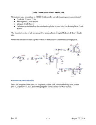
The feedstock to the crude system will be an equal mix of Light, Medium, & Heavy Crude
oils.
When the simulation is set up the overall PFD should look like the following figure.
Create new simulation file
Start the program from Start, All Programs, Aspen Tech, Process Modeling V8.6, Aspen
HYSYS, Aspen HYSYS V8.6. When the program opens choose the New button.
2. Rev 1.2 - 2 - August 27, 2016
Define the Components & the Property Models
Specify components, fluid property packages, & crude oil assays
The first step is to add a set of pure chemical species to represent the light components of
the crude oils. With Component Lists highlighted click on the Add button. From the list of
pure components pick water, methane, ethane, propane, i-butane, n-butane, i-pentane, & n-
pentane.
The next step is to pick a fluid property package. From the Fluid Packages screen click the
Add button. Choose the Peng-Robinson option and make sure it is associated with
Component List – 1.
3. Rev 1.2 - 3 - August 27, 2016
We now want to add assay data for the three crude oils: Light Crude, Medium Crude, &
Heavy Crude. The data to be added is shown in the following tables.
Table 1. Assay Data for Light Crude
Light Crude
Cumulative Yield
[wt%] Density Sulfur Light Ends Analysis
IBP EP @ IBP @ Mid lb/ft31
wt% [wt%]
Whole Crude 53.27 1.77 Ethane 0.000
31 160 0 2.5 42.75 0.019 Propane 0.146
160 236 5 7.5 45.40 0.031 i-Butane 0.127
236 347 10 15 48.33 0.060 n-Butane 0.702
347 446 20 25 50.46 0.379 i-Pentane 0.654
446 545 30 35 52.38 1.064 n-Pentane 1.297
545 649 40 45 54.18 1.698
649 758 50 55 56.04 2.159
758 876 60 65 57.92 2.554
876 1015 70 75 60.05 3.041
1015 1205 80 85 62.84 3.838
1205 1350 90 92.5 64.92 4.503
1350 FBP 95 97.5 70.64 6.382
1 Note that HYSYS uses a water density to convert to specific gravity of 62.3024 lb/ft³ =8.32862 lb/gal =
997.989 kg/m³.
5. Rev 1.2 - 5 - August 27, 2016
The following steps show how to enter the data for Light Crude. Similar steps should be
used for the other crude oils. The steps will be shown using the Oil Manager2.
Click on the Oil Manager button in the Home tab. You will have the options to install
individual crude oil assays & then create a blend of the assays.
Click on the Input Assay button & then the Add button. In the Assay Definition
section we want to use Bulk Properties, specify a TBP Assay Data Type, input
compositions for the Light Ends, and input an independent Density Curve. Ensure the
Assay Basis is Mass. When all of these are specified the Input Data should look like
below.
2 Though the Assay Manager is more powerful it requires a special license which may not be available to you
at your location.
6. Rev 1.2 - 6 - August 27, 2016
Let’s input the TBP curve on a wt% basis for Light Crude. Click on the Edit Assay…
button. Since we will be entering 12 data points enter 11 for the Num of Points to
Add & click the Add Data Points button (since 1 is already showing). Now the table of
Cumulative wt% Yield values (scaled 0 to 100) vs. temperatures (in °F) can be
entered. Click OK.
Now we’ll add in the composition of the light ends. Make the Light Ends option
active & the form will change to allow you to enter the compositions (based on the
component list previously specified). Make sure you change the Light Ends Basis to
Mass%.
7. Rev 1.2 - 7 - August 27, 2016
Now we’ll add in the density data. Make the Density option active & the form will
change to show you the density vs. yield data entered. Click on the Edit Assay…
button. Since we will be entering 12 data points enter 11 for the Num of Points to
Add & click the Add Data Points button (since 1 is already showing). Now the table of
Cumulative wt% Yield values at the middle of the cut (scaled 0 to 100) vs. standard
liquid density values (in lb/ft3) can be entered. Click OK. Note that even though the
standard liquid density might be in the crude oil assay in other forms (such as
specific gravity of API gravity) HYSYS will request the information in a specific form
& it cannot be changed on this form.
8. Rev 1.2 - 8 - August 27, 2016
Let’s finish adding in the data needed to characterize the assay and allow HYSYS to
create pseudo components. Make the Bulk Props option active & the form will
change to allow you to enter the data. The only information we have to add is the
standard liquid density for the whole crude. Enter this value in the Standard Density
field. Note that other units can be used on this form. Further note that whatever
units are used for the data entry HYSYS will convert the value to the units and form
it is expecting (in this case API gravity).
Even though we can now characterize the pseudo components for the flash
calculations we still need to add the sulfur distribution so that this can be tracked.
First we’ll have to define a User Property that represents the sulfur content. Click on
User Properties either from the tree structure in the left-hand column or the
appropriate button under the Home tab. When the User Properties form comes up
press the Add… button.
9. Rev 1.2 - 9 - August 27, 2016
On the UserProp-1 form choose the Mass Fraction option & leave the F1 and F2
mixing parameters as 1. Set the values for the pure components as zeroes.
Let’s make the label for this property more meaningful. Return to the User
Properties tab and single click the UserProp-1 label. Now type in Sulfur.
10. Rev 1.2 - 10 - August 27, 2016
Now we can add the sulfur distribution for the assay. Click on Assay-1 in the tree
structure in the left-hand column & choose the User Curves tab. Highlight Sulfur in
the Available Properties column & press Add--->. Under the User Curve Data area
retain the Independent setting for the Table Type, enter the whole crude value for
the Bulk Value, and set the lower and upper limits to 0 and 100. Press the Edit…
button at the bottom of the form to enter the assay values. Press OK.
11. Rev 1.2 - 11 - August 27, 2016
One more thing to clean up for the assay, changing its name. Click on Input Assay in
the tree structure of the left-hand column. In the Input Assay form single click Assay-
1 & type Light Crude.
Repeat the steps for the Medium & Heavy Crudes.
Do characterization calculations, specify crude oil blend, & install into flowsheet
After entering the assay we have to tell HYSYS to perform the characterization calculations.
Select each crude oil in the tree structure of the left-hand column & click on the Calculate
button if there is a warning that the assay has not been calculated. When properly
calculated there should be a message in green.
12. Rev 1.2 - 12 - August 27, 2016
Now we’ll create a blend of the three crudes and use that as our feedstock in the simulation.
Select Output Blend in the tree structure of the left-hand column. On the Output Blend tab
select the Add button. On the Blend-1 tab select the crudes & press Add--->. Accept the
Liquid Vol option for the Flow Units. Enter three equal flow units under Flow Rate, such as
33 kbpd (thousands of barrels per day).
If all of the crude oils have been characterized previous to this then you should receive a
Blend Was Calculated message in green.
One more cleanup step, changing the name of the blend. Select Output Blend in the tree
structure of the left-hand column. In the tabbed form select Blend-1 and change to Mixed
Oil.
13. Rev 1.2 - 13 - August 27, 2016
The next step is to install the blend into the flowsheet. From this tabbed form select Oil
Manager and then select Install Oil from the next form. Now we get a form that we can
install one or more of the oils. We’re only interested in installing the blend, Mixed Oil. In the
Stream Name column enter Crude Blend for Mixed Oil. Click Install.
As a final step let’s make sure everything is calculated & the pseudo components are
installed into the component list. Select Oil Manager in the tree structure in the left-hand
column. At the bottom of the form click Calculate All. Now when you look at the Component
List you should see a series of pseudo components after the pure components chosen
earlier.
14. Rev 1.2 - 14 - August 27, 2016
Set up & Solve the Flowsheet
Crude Oil Feed & Preheat
When you activate the Simulation you’ll see a single steam called Crude Oil. We want to
attach this stream to two heat exchangers (to model the preheat before & after the
Desalter) and a Mixer to set an expected amount of water in the Crude Oil coming from the
Desalter.
The following are the conditions to be set on the operations.
Crude Oil Feed: 100°F, 300 psig, 101,000 bpd
Preheat-1 outlet: 260°F, 294 psig
Desalter outlet: 260°F, 294 psig, 500 bpd of water
Preheat-2 outlet: 450°F, 260 psig
Double-click on the Crude Oil stream to open up the entry forms for this stream. Note that
the flow rate comes from Oil Manager, but we’re going to overwrite this. Note that once you
enter the pressure & temperature the calculations for Crude Oil are complete & it takes on a
new color in the flowsheet.
15. Rev 1.2 - 15 - August 27, 2016
For the heat exchangers the stream connections are done on the Design tab, Connections
selection. There are two ways to specify the outlet conditions. The most direct is to set both
temperature & pressure via the Worksheet tab.
This is what the form looks like before making outlet specifications:
16. Rev 1.2 - 16 - August 27, 2016
After making outlet specifications:
The entrained water is set by opening up the input form for Desalter Water. On the
Worksheet tab select Composition. Click on the Edit… button, enter 1 for the fraction of H2O,
click the Normalize button, and then OK. Next we will set the pressure of the entrained
water (same as the outlet from the Desalter) & the flowrate. Note that we will not set the
temperature at this time.
17. Rev 1.2 - 17 - August 27, 2016
Now let’s set the conditions for the outlet of the Desalter. Double click on the Mixer and
click on the Worksheet tab. Note that the pressure of the outlet stream has been determined
(set as the lowest pressure of all streams being mixed) & the standard liquid flowrate has
been determined (since this is just additive of the two streams into the Mixer). Now, let’s
specify the temperature of the outlet of the Desalter; note that the temperature of the water
stream has been back-calculated to make sure the outlet temperature is correct.
Before specifying outlet temperature:
After specifying outlet temperature:
Specifying outlet conditions on the second preheater completes the flowsheet calculations
for this part of the simulation.
Atmospheric Distillation Column
The next step is to set up the Atmospheric Distillation Column. Table 4 contains the
conditions & configuration for this column.
18. Rev 1.2 - 18 - August 27, 2016
The fired heater on the feed is separate from the column environment & will be created
first. Create a new Heater on the flowsheet & call it Atm Heater. Change the icon to look like
a heater instead of a shell & tube heat exchanger. Enter the following connections & set the
following outlet conditions to match the approximate atmospheric column conditions in
Table 4.
This portion of the PFD should look like the following.
Setting up a distillation column is a multi-step process in HYSYS. First, create a Refluxed
Absorber Column on the flowsheet then start to fill in the information.
19. Rev 1.2 - 19 - August 27, 2016
Table 4. Definitions for Atmospheric Distillation Column
Type Operating Parameter
Trays & Efficiencies 50 trays. Numbering from top:
Trays 1 to 6: 80%
Trays 7 to 10: 50%
Trays 11 to 16: 70%
Trays 17 to 30: 50%
Trays 31 to 39: 30%
Tray 40: 100%
Trays 41 to 50: 30%
Condenser Type Total Condenser; 130°F (approximate)
Distillate product 410°F D86 T95; 30,200 bpd (approximate)
Reboiler Type None, Direct Fired Heater
Pressures Condenser: 4 psig
Top Tray: 12 psig
Bottom Tray: 22 psig
Temperatures Top Tray #1 250°F (estimate)
Bottom Tray #50 650°F (estimate)
Feed Locations Crude oil to Tray #40
Stripping Steam at bottom (Tray #50) – 20,000 lb/hr @ 500°F, 150 psig
Feed Heater Outlet @ 25 psig & 635°F
Desire is 2,500 bpd overflash (liquid rate from tray above feed, Tray #39)
Side Strippers Kerosene Stripper
10 trays @ 30% efficiency
Kerosene draw from Tray #10, vapor returned to Tray #6
Stripping steam @ bottom (Tray #10) – 2500 lb/hr @ 500°F & 150 psig
Kerosene product 525°F D86 T95; 8800 bpd product (approximate)
Diesel Stripper
10 trays @ 30% efficiency
Diesel draw from Tray #20, vapor returned to Tray #16
Stripping steam @ bottom (Tray #10) – 2500 lb/hr @ 500°F & 150 psig
Diesel product 645°F D86 T95; 10,240 bpd product (approximate)
AGO Stripper
10 trays @ 30% efficiency
AGO draw from Tray #30, vapor returned to Tray #26
Stripping steam @ bottom (Tray #10) – 2500 lb/hr @ 500°F & 150 psig
AGO product 750°F D86 T95; 3835 bpd product (approximate)
Pumparounds Kerosene Pumparound
Draw from Tray #10, returned to Tray #7
25,000 bpd flow, 200°F return temperature
Diesel Pumparound
Draw from Tray #20, returned to Tray #17
15,000 bpd flow, 250°F return temperature
AGO Pumparound
Draw from Tray #30, returned to Tray #27
10,000 bpd flow, 350°F return temperature
20. Rev 1.2 - 20 - August 27, 2016
When you double click on the column for the first time a wizard starts and will guide you
through entering information. If you don’t fill it all in, don’t worry – you can always specify
the information from the forms & column sub-flowsheet.
The first step in the wizard is to set up the basic information for the main feeds & products
(but not the side products which will be processed through side strippers). Fill in the
information as shown below. Make sure you check the box for Water Draw. When done
press Next>.
The next step is to set up the basic pressure profile in the column. Fill in values & press
Next>.
On the third screen we will set an estimate for the condenser temperature. Press Next>.
Though the other temperatures are not required it usually good practice to enter values.
21. Rev 1.2 - 21 - August 27, 2016
For a atmospheric crude tower reasonable starting points are 250°F & 650°F for the top &
bottom stages, respectively.
On the fourth screen we’ll set an estimate for the distillate rate. Press the Side Ops> button
to start setting up the side strippers & pumparounds.
We’ll skip this first side operation screen since none of the side strippers are reboiled.
Press Next>.
Now we can start adding the basic information for the three side strippers. To start
entering the configuration information for each side stripper press the Add Side Stripper
22. Rev 1.2 - 22 - August 27, 2016
button; when done press the Install button. When done with the three side strippers press
the Next> button.
We do not have any side rectifiers. Press the Next> button.
Now we can start adding the basic information for the three pumparounds. To start
entering the configuration information for each pumparound press the Add Pump-Around
button; when done press the Install button. When done with the three pumparounds press
the Next> button.
We do not have any vapor bypasses. Press the Next> button.
Now we can enter the side product flows through the side strippers. Enter the estimates for
the flowrates out the bottom of the strippers & then press Next>.
23. Rev 1.2 - 23 - August 27, 2016
Now we can set the specs on the pumparounds. Enter the flowrate values & the values
associated with the heat exchanger duties. Note that all of the duty/temperature specs are
Return T type. When done press Next>.
Now we can set the pressures in the side strippers. Use the default values with no changes.
Press Next>.
Now we can set the pressure drops across the pumparounds. Use the default values of zero.
Press Done.
Distillation columns are different from the rest of the HYSYS operations in that they do not
automatically run the first time they are created; rather, you must press the Run button
when everything has been set up properly. However, we still have a couple more changes
to make so let’s not do this yet.
First, let’s specify the stage efficiencies to model the stages as real trays. Under the
Parameters tab select Efficiencies. Make sure that Overall & User Specified items are
24. Rev 1.2 - 24 - August 27, 2016
highlighted. Now let’s start applying the efficiencies in Table 4. Note that stages associated
with the side strippers are listed in this table as if part of the main column (in a way they
are, but that’s a subject for a different discussion).
The next requirement is to specify the steam streams. This can be done using the
Worksheet tab. Select Conditions and specify the temperature, pressure, & mass flowrate
values. Select Compositions; now the compositions can be set as 100% H2O (entering a
value of 1 will bring up the Input Composition form; press the Normalize button & then OK).
25. Rev 1.2 - 25 - August 27, 2016
Even though we don’t have all of the operating specs added we can do an initial run of the
simulation by pressing Run. You should get a converged solution in about 4 iterations.
How can the distillation column equations be solved without putting the composition
specs? This is because the “estimated” flowrates entered during the setup are used as the
actual specifications. We can see this by checking the Spec Summary setting under the
Design tab. Notice that all of these flowrate specs have checks in the Active column; this
means that these values are the specifications to which the solution is driven.
26. Rev 1.2 - 26 - August 27, 2016
Let’s now add the composition specs but not make them active. Select Specs under the
Design tab. In the Column Specifications area we can add, remove, or change any of the
specs that will show up in the Summary. Let’s first add the ASTM D86 95 vol% temperature
spec for the Naphtha stream. Click Add… In the list that comes up choose Column Cut Point
(do not choose End Point Based Column Cut Pint Spec near the bottom of the list) & click Add
Spec(s)… Call the spec Naphtha D86 T95, associate the spec with the liquid phase off of the
Condenser, set the % as 95, and set the Spec Value as 410°F. (Keep the default API 1974
conversion method.) You can now close the form.
27. Rev 1.2 - 27 - August 27, 2016
Once we close the input form we can see information about the specification details. The
value is supposed to be 410°F but because the spec is not active the value is only 398.1°F.
Close, but not close enough. In the actual operation of the tower we would adjust the
distillate draw rate to make this spec. In HYSYS we make the Naphtha Rate spec inactive &
make the Naphtha D86 T95 spec active. The easiest way to do this is from the Specs
Summary form. Changing the check boxes will cause the tower to rerun & quickly converge.
Now when we check the individual specs by selecting Specs under the Design tab we see
that the Naphtha Rate value is 28,970 bpd, not the 30,200 bpd estimate.
We can create similar design specs for the Kerosene, Diesel, & AGO D86 T95 values. Each
time we make the T95 spec active we will make the corresponding produce rate inactive.
28. Rev 1.2 - 28 - August 27, 2016
Debutanizer Column
Next, let’s do the simpler of the two remaining columns, the Debutanizer Column (i.e., the
Naphtha Stabilizer). We will want to operate the Debutanizer at a higher pressure than the
Atmospheric Distillation Column, so we will need a pump for the Unstabilized Naptha. We
will also preheat the feed entering the column. Table 5 shows the operating conditions for
the column & the feed’s pump & preheater.
Table 5. Definitions for Debutanizer Column
Type Operating Parameter
Feed Prep Increase pressure to 250 psig; use default adiabatic efficiency for pump (75%)
Preheat to 250°F; assume negligible pressure drop through exchanger
Trays & Efficiencies 45 trays. Number from top. All trays 80% efficiency
Condenser Type Total condenser
1.5 reflux ratio
Reboiler Type Kettle reboiler
Pressures Condenser: 150 psig
Top Tray: 150 psig
Bottom Tray: 160 psig
Reboiler: 160 psig
Temperature No other estimates needed
Feed Locations Unstabilized Naphtha to Tray #22
Products Overhead LPGs, 5,500 bpd
Stabilized naphtha from bottom
29. Rev 1.2 - 29 - August 27, 2016
Place a Pump on the flowsheet & define the following connections. Retain the default
adiabatic efficiency. Set the outlet pressure as 250 psig in the Worksheet tab.
30. Rev 1.2 - 30 - August 27, 2016
Place a Heater on the flowsheet & define the following connections. Set the pressure drop
in the Parameters section. Since the outlet pressure is calculated from the pressure drop it
does not have to be set on the Worksheet tab. However, we still need to set the outlet
temperature & this can be done on the Worksheet tab.
31. Rev 1.2 - 31 - August 27, 2016
Now we can define the Debutanizer. Just like with the Atmospheric Distillation Column
HYSYS will start the process with a 5 step wizard to walk you through the basic
configuration. From the Columns tab in the model Palette chose the Distillation Column sub-
flowsheet (the one with both a condenser & a reboiler).
The next step is to pick a type of reboiler. The first entitled Once-through depicts a kettle
reboiler & is the one we want (liquid from the bottom tray is the feed to the reboiler,
produced vapors are returned to the bottom tray and the liquid exits as the bottoms
product). The other two configurations are for thermosiphon reboilers; though used
commercially they will not be chosen for this example. Click Next> when done.
The next form is for entering the basic pressure profile. Enter the values from Table 5. Click
Next> when done.
32. Rev 1.2 - 32 - August 27, 2016
For this tower we will skip entering temperature estimates. Click Next>.
On the next form enter the reflux ratio & distillate rate. Click Done when finished.
The final step before trying to run is to specify the stage efficiencies to model the stages as
real trays. Under the Parameters tab select Efficiencies. Make sure that Overall & User
Specified items are highlighted. Apply the same efficiency to all stages representing trays,
leaving the efficiencies for the Condenser & Reboiler at 1.0.
33. Rev 1.2 - 33 - August 27, 2016
Now we can click on the Run button. The convergence should be very rapid.
Vacuum Distillation Column
The final step is to define the feed heater & Vacuum Distillation Column. Additional steam
is injected into the Vacuum Feed Heater to increase velocity & minimize coke formation
within the heater. Even though the Vacuum Column is packed it will be modeled as “trays,”
i.e., sections of non-equilibrium stages.
The first step is to mix the Atm Resid from the Atmospheric Distillation Column with the
steam upstream of the Vacuum Heater. Place a Mixer on the flowsheet & define the
following configuration. You will have to define the steam stream; this can be done via the
Worksheet tab.
34. Rev 1.2 - 34 - August 27, 2016
Table 6. Definitions for Vacuum Distillation Column
Type Operating Parameter
“Trays” & Efficiencies 14 trays. Numbering from top:
Tray 1: 100%
Trays 2 to 11: 50%
Tray 12: 100%
Trays 13 to 14: 30%
Condenser Type No condenser, LVGO pumparound liquid return to top stage
Reboiler Type None, Direct Fired Heater
Pressures Top Tray: 50 mmHg
Bottom Tray: 62 mmHg
Temperatures Top 180°F (controlled by top LVGO pumparound)
Feed Locations Crude oil to Tray #12
Stripping Steam at bottom (Tray #14) – 20,000 lb/hr @ 500°F, 150 psig
Feed Heater 20,000 lb/hr steam injected into heater coils with the Atmospheric Resid feedstock
(500°F & 150 psig)
Outlet @ 180 mmHg & 760°F (max); would like 3,000 bpd excess wash liquid (liquid rate
from tray above feed, #11)
Pumparounds LVGO Pumparound
Draw from Tray #4, returned to Tray #1
22,300 bpd flow, outlet temperature adjusted to control top temperature of tower;
approximately 85°F, 42 MMBtu/hr cooling
HVGO Pumparound
Draw from Tray #8, returned to Tray #5
50,000 bpd flow, 150°F cooling
Products LVGO from Tray #4; 915°F D1160 T95; 5,000 bpd (approximate)
HVGO from Tray #8, 1050°F D1160 T95; 21,000 bpd (approximate)
Slop Wax from Tray #11, 1,000 bp
Vacuum resid from bottom
The fired Vacuum Heater is separate from the column environment & will be created next.
Create a new Heater on the flowsheet & call it Vac Heater. Change the icon to look like a
heater instead of a shell & tube heat exchanger. Enter the following connections & set the
35. Rev 1.2 - 35 - August 27, 2016
following outlet conditions to match the vacuum column conditions in Table 6. Note that
even though the pressure is specified as 180 mmHg(0C) the value is immediately converted
to the units used in the flowsheet, here psig3.
Configuring the Vacuum Column for the first time is a multi-step process. First, create an
Absorber Column on the flowsheet then double-click start to fill in the information. Fill in
the basic information for the configuration on the first form. Couple things that are
different from the previous two columns:
Specify that the top stage reflux comes from a Pump-around (note that HYSYS will
define this first pumparound & give it a default name; this can be changed later).
Specify the LVGO, HVGO, & Slop Wax streams on this form as Optional Side Draws
(since they are not processed further in side strippers). Note in the image below that
only 2 Optional Side Draws are shown; you will have to scroll down to see the
connection for the Slop Wax.
3 Be very careful which units you choose for the pressure. If you choose mmHg(0C)_g by mistake you’ve
specified a gauge pressure & will be much too high since it would be above 1 atm instead of at vacuum
conditions.
36. Rev 1.2 - 36 - August 27, 2016
On the next form we’ll initialize the pressure profile. Again, even though the pressures are
input in units of mmHg(0C) they get converted to psig. Click Next>.
The next form will allow us to add temperature estimates & flow information for the top
pumparound. Enter the data for the LVGO Pumparound. We will skip adding temperature
estimates on this form & show how they can be added later. Click Side Ops>.
37. Rev 1.2 - 37 - August 27, 2016
There are no side strippers or rectifiers so skip the next 3 forms for Reboiled Side Stripper
Connections, Steam Stripped Side Stripper Connections, & Side Rectifier Connections.
There is already one pumparound defined (since we specified a pumparound return to
provide the top stage reflux). Let’s changed the Name from the default to LVGO
Pumparound. Then click Add Pump-Around and define the HVGO Pumparound. Click Next>
when done.
We will skip the next form for Vapor Bypass Connections.
The next form allows us to add the HVGO Pumparound specs. Note that the specs for the
LVGO Pumparound were previously entered & are shown here. Click Next> when done.
38. Rev 1.2 - 38 - August 27, 2016
On the last form we will accept zero pressure drops through the pumparounds. Click
Done…
Before we try running the column we need to enter the efficiencies for the stages. Select
Efficiencies under the Parameters tab & enter the values from Table 6.
39. Rev 1.2 - 39 - August 27, 2016
We skipped adding temperature estimates before but we can add them now. Go to the
Profiles item under the Parameters tab. It’s pretty typical to have a top temperature of
about 150°F (this will actually be changed to be our specification) & a bottom temperature
of 700°F. You may also want to specify the 2nd stage temperature of 325°F (since there is a
significant cooling between the top & next stage).
Before we can run the column we have to specify something about the side draws (LVGO,
HVGO, & Slop Wax). Let’s specify the estimated flowrates and use these as specifications.
For example, for the Slop Wax rate, select the Specs item in the left-hand column under the
Design tab & press Add… Call the spec Slop Wax Rate, associate with the Draw named Slop
Wax @COL3, set the flow basis as Std Ideal Vol, and set the rate as 1 kbpd.
40. Rev 1.2 - 40 - August 27, 2016
Now let’s change the performance of the LVGO Pumparound to adjust the return
temperature in that pumparound to meet the temperature spec at the top of the column.
Select the Specs item under the Design tab & add a spec for the top temperature. To make it
active go to the Spec Summary item, uncheck the LVGO Pumparound_TRet(Pa) & check the
Top Temperature spec.
Now we can press Run. The Vacuum Column should converge fairly quickly.
41. Rev 1.2 - 41 - August 27, 2016
We can add the D1160 specs for the LVGO & HVGO in a similar manner to the Atmospheric
Column specs except that these streams are direct liquid draws from the main column & do
not go through side strippers. To set the LVGO spec first Add a Column Cut Point from the
Specs item on the Design tab. However, for right now we do not want to make them active;
click on the Summary tab & uncheck the Active box. You can also go to the Specs Summary
item & make sure that these new D1160 specs are not checked in the Active column.
It is also useful to add specs for the liquids flowing from the LVGO to the HVGO section
(from tray #4) and the HVGO to feed tray (from tray #11). These can be added as a Column
Liquid Flow spec. Make sure you specify the values as Std Ideal Vol for the Flow Basis &
ensure that the Active box is unchecked on the Summary tab’s form.
42. Rev 1.2 - 42 - August 27, 2016
Before we apply the D1160 specs for the HVGO & LVGO let’s examine some of the internal
flowrates. The most important is the liquid runback to the feed tray; this will be the liquid
rate from Tray #11. Select the Specs item under the Design tab & then select the Net from
#11 item in the Column Specifications. In the Specifications Details area we can see that we’d
like to apply a Specification Value of 3,000 bpd & currently have 4,888 bpd. We have some
flexibility to pull additional HVGO and/or LVGO without drying up the column.
Let’s look at the HVGO D1160 T95 value. We want 1050°F & we actually have 1044°F. This
is very close; we’ll increase the HVGO draw rate to increase this value to the spec. Go to the
Spec Summary, uncheck the Active box for HVGO Rate, & check the Active box for HVGO
D1160 T95. The simulation should quickly converge. Go back to the Specs form to check the
actual HVGO D1160 T95 value; it should be 1050°F. (If not, press, Reset & Run.) Note that the
HVGO rate is large as expected, 21.47 kbpd vs. 21.00 kbpd. Also note that the Net from #11
flowrate has decreased slightly to 3,961 bpd.
Now let’s look at the LVGO results. For 5,000 bpd LVGO rate the D1160 T95 value is too
low. Since the T95 value is too low, we will have to increase the LVGO draw rate to try to
meet this spec. Let’s apply this D1160 spec instead of the flowrate spec. The column will
converge. The LVGO flow rate has increased to 7,534 bpd, the HVGO flow rate has actually
decreased to 18,700 bpd, and the Tray #11 liquid runback has increased to 4,462 bpd.
Let’s go back to the runback rate. This rate is too large & how could we decrease? We
actually have to back up to the Feed Heater & decrease the temperature so that we don’t
boil up as much gas oils. We can manually adjust to 749.6°F to get 3,011 bpd runback from
Tray #11.
43. Rev 1.2 - 43 - August 27, 2016
Stream & Unit Analyses
Now that the simulation has been run & converged we want to be able to analyze the
results. First we’ll look at ways of further examining unit & stream results.
First, let’s look at the temperature & liquid/vapor traffic in the Atmospheric Column. Let’s
double click on Atm Col & click on the Parameters tab. Select the Profiles option & you can
see the temperatures, pressures, & liquid & vapor flows for all of the trays (including the
side stripper trays at the bottom of the list). Notice there are several options for showing
the liquid & vapor flows: molar, mass, & 3 types of volume. The molar & mass quantities
should be self-evident, but the volume factors are somewhat confusing:
Act. Volume – this is the volumetric flow based on the density at the temperature &
pressure conditions (as calculated by the corresponding density method, usually
COSTALD). This is the most appropriate value to use when determining the
hydrodynamics on the tray & within the column.
Volume – this is the standard liquid volume as calculated from each component’s
specific gravity value & blended by the mass amount of each component in the
mixture assuming ideal mixing (i.e., no shrinkage effects). This is the most normal
definition for “standard liquid volume.”
Std Ideal Vol – this is the volumetric flow calculated, not at the actual pressure &
temperature for the fluid, but rather at the standard temperature & bubble point
pressure (again by the COSTALD method). This will be very similar to the Volume
value but will include shrinkage effects. This is a value calculated by HYSYS but very
few other simulation programs.
44. Rev 1.2 - 44 - August 27, 2016
Which of these values should you use? This depends on your purpose:
If you’re trying to track how much of each fraction goes out with each side stream,
then use the Volume values. As long as there is no chemical reaction these values are
conserved (since they are essentially a transformed mass amount).
If you are doing hydraulic calculations then use the Act Volume values.
If you want to determine the ideal gas flows (such as scf of a produced light gas)
then start with Molar flow values & convert the units as appropriate.
What are some of the properties of interest for streams? In general we will want to know:
How much?
What quality?
At what conditions?
Let’s first look at the Kerosene stream. We can double click on the Kerosene stream in the
Flowsheet & look at the Conditions item under the Worksheet tab. This shows us answers to
“how much” & “at what conditions.” We can see the pressure & temperature, flowrate in
various sets of units (mass, molar, standard liquid volume, & actual volumetric flow at
operating conditions).
If we want to see other physical properties for this stream we would select the Properties
item. Now we can see an extensive set of physical & transport properties for this stream.
This answers a great deal of the “what quality” questions.
45. Rev 1.2 - 45 - August 27, 2016
The Composition item will show tables of the stream’s
composition using multiple possible bases: molar,
mass, & standard liquid volume. The default will
generally be for mole fractions. But pressing the
Basis… button will allow you to change to other types
on both fractional & flowing values. When working
with petroleum fluids the liquid volume fractions or
flows are very convenient.
47. Rev 1.2 - 47 - August 27, 2016
Since we are working with petroleum streams we may also want to determine the
distillation curve associated with a stream composition. For this we’ll use one of the Stream
Analysis options. You can create a stream analysis for the first time by right-clicking on a
stream & choosing Create Stream Analysis> & then Boiling Point Curves. A more general way
to create a new analysis or review an existing analysis is to choose the Steam Analysis drop
down list & choosing the Boiling Point Curves option in the Home tab of the ribbon. Choose
the Kerosene stream & click OK.
Please note that there is a second similar option, Petroleum Assay, but do not choose
this. The two options give slightly different results. The Boiling Point Curves option
is consistent with the correlations used for the tower specs. The Boiling Point Curves
option is also consistent with what can be calculated using the amounts & boiling
points for the pseudo components.
48. Rev 1.2 - 48 - August 27, 2016
Note that we have various distribution curves based on the cumulative yield for the stream.
Two of the curves that will be of most interest are the TBP & ASTM D86 curves. Note that
not only can we get the results in tabular form but we can also directly make a plot.
49. Rev 1.2 - 49 - August 27, 2016
Export results to spreadsheet
There are many times that you’d like to create a general table of stream and/or unit results
to a spreadsheet so that you pick & choose various values for ad hoc reports. There are a
couple options for doing this.
HYSYS has a default
workbook that summarizes
a great deal of the stream &
unit information in a single
location. Click on the
Workbook button under the
Home tab of the ribbon &
choose the default
workbook for Case (Main).
You should see a series of tabs that summarize the input & calculated results for the main
flowsheet: conditions for the material streams, mole fractions for the pure & pseudo
components for the material streams, values for the energy streams, & a summary listing
for the unit operations.
50. Rev 1.2 - 50 - August 27, 2016
Let’s look at the table of Material Streams. Note that the default format is to have
information for each stream in a column & items of information in each row. One might
expect that the columns would continue out of view off to the right. Instead, however, only
a small set of columns are shown & then the information for the next set of columns is
shown below. This is unfortunate in that if you were to copy & paste into a spreadsheet this
same format is retained. This can be demonstrated by:
open up Excel
go back to HYSYS & select any cell
right-click & choose Select All
right-click & choose Copy
highlight any cell in Excel (preferably A1)
paste (either by pressing Ctrl-c or right-click & select the paste text icon). After
resizing the columns in Excel you should see table like below.
51. Rev 1.2 - 51 - August 27, 2016
There is an option to directly export the workbook information directly to Excel. Press the
Excel button on the Workbook tab in the ribbon. Choose which of the pages you’d like to
export (here we’ll choose them all) & how many columns to produce before repeating
below (50 should be sufficient for this example). Press Export to Excel. A set of macros will
run that will open a new Excel spreadsheet & values will be copied from the HYSYS
simulation to the spreadsheet. Be patient, this may take a while. (It might be a good time to
get up & get that cup of coffee you’ve been wanting.)
52. Rev 1.2 - 52 - August 27, 2016
After adjusting column widths the product spreadsheet will look like the following. Note
that there will be at least 50 columns before the information is repeated below row 9. Also,
the color formatting showing the user input values (in blue) is retained.
53. Rev 1.2 - 53 - August 27, 2016
There are a couple limitation to this
default workbook report. One is the
information reported in the
Composition tab – it is only for the
mole fractions. For petroleum
streams liquid volume fraction
would be more convenient. To get
this then you’ll have to create a
custom workbook sheet and/or
report.
Let’s look at some report options that come with HYSYS. Click on the Reports button in the
Home tab of the ribbon. At the bottom of the form we’ll want to choose one of the existing
templates for the Excel Reports. Click on the Browse Template button. On the next window
choose petroleum-refining.wrk (make sure you’re in the appropriate folder to choose this).
Now when you click on the Create button a set of macros will run that will open a new Excel
spreadsheet & values will be copied from the HYSYS simulation to the spreadsheet. This
will also take a while. (It might be a good time to refill that cup of coffee.)
55. Rev 1.2 - 55 - August 27, 2016
The Excel spreadsheet produced this time
has additional information useful for
analyzing petroleum streams. If you look
at the Compositions tab you’ll see that this
still reports mole fractions (so no
difference here). But if you look at the
Material Streams tab you can see that a lot
of the data from the Conditions &
Properties items are in the Material
Streams tab. This will also contain the TBP
& D86 assay information from the Steam
Analysis. (Unfortunately these are boiling
point curves consistent with the
Petroleum Assay option; we will not want
to use these.)
Let’s go back to HYSYS & look at the workbook for Case (Main). Notice that the Materials
Streams tab has now been modified with the extra petroleum-related information that we
see in the Excel spreadsheet. This shows that customizing the workbook & subsequently
exporting to Excel is possible.
Let’s create a new tab in the workbook for the liquid volume flows for each component.
Select Setup under the Workbook tab in the ribbon. Let’s Add a new Workbook Tab. Select
the Material Stream type. Now there is a new tab called Material Streams 1 with the basic
stream conditions.
57. Rev 1.2 - 57 - August 27, 2016
Let’s change
the Name to
Liquid Volume
Flows.
Highlight all of
the variables in
the Variable
list & press
Delete. Now we
can create a
brand new list
of variables.
58. Rev 1.2 - 58 - August 27, 2016
Press the Add… button. From the
Variable list select Master Comp
Volume Flow & press the All
button. Now we’ll get a table with
all of the liquid volume flow values
for each pure & pseudo
component. However, before we
commit to this, let’s remove the “
(Methane)” from the Description so
it only says “Master Comp Volume
Flow”. Now we can press OK. We
can close the Setup form & see that
there is now tab for these
component volume flows.
Let’s address the issue with the distillation curves that are part of the create a new tab in
the workbook for the liquid volume flows for each component. Select Setup under
petroleum-refining.wrk additions. Let’s create a workbook table that reports the Boiling
Point Curves for the stream analyses set up in the simulation. Go to the Workbook tab &
press Setup. Similar to what was done before, choose Add. But this time expand the Utility
Objects item & select Boiling Point Curves & press OK. Rename the tab Boiling Point Curves;
there should be no the default items in the list.
60. Rev 1.2 - 60 - August 27, 2016
Press the Add… button. From the
Variable list select ASTM D86 &
highlight All, & press the OK
button. Now we’ll get a table with
all of the ASTM D86 values as
calculated by the routines for the
Boiling Point Curves.
Repeat the steps & choose True BP. This will the TBP values at the bottom the table.
61. Rev 1.2 - 61 - August 27, 2016
Now the boiling point curves from the Stream Analyses will be part of the workbook. (Note
that if you did not set up a Stream Analysis for a stream it will not be h ere either.) This
spreadsheet can also exported to Excel.