
Recommended
Recommended
More Related Content
What's hot
What's hot (20)
Similar to Structural Health Monitoring using Rebounding Hammer Test
Similar to Structural Health Monitoring using Rebounding Hammer Test (20)
More from ijtsrd
More from ijtsrd (20)
Recently uploaded
Recently uploaded (20)
Structural Health Monitoring using Rebounding Hammer Test
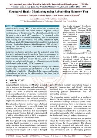
- 1. International Journal of Trend in Scientific Research and Development (IJTSRD) Volume 7 Issue 3, May-June 2023 Available Online: www.ijtsrd.com e-ISSN: 2456 – 6470 @ IJTSRD | Unique Paper ID – IJTSRD57464 | Volume – 7 | Issue – 3 | May-June 2023 Page 631 Structural Health Monitoring using Rebounding Hammer Test Umashankar Prajapati1 , Rishabh Tyagi2 , Aman Tomar3 , Gaurav Gautam4 1 Assistant Professor, 2, 3, 4 B.Tech Final Year Student, 1, 2, 3, 4 Raj Kumar Goel Institute of Technology, Ghaziabad, Uttar Pradesh, India ABSTRACT Non-destructive testing (NDT) is a technique used to evaluate the condition of structures and collect material properties without causing damage to the specimens. The rebound hammer test is one of the most regularly used NDT procedures. For structural health monitoring, several techniques are frequently used, including ultra- pulse velocity, half-cell potential, core cutter, carbonation depth, rebar finder, quick chloride penetration test, electric resistivity meter test, and vibration-based analysis. Visual inspection, NDT, laboratory testing, and field testing are all viable methods for determining a structure's condition. Concrete's mechanical properties can be estimated using both destructive and non-destructive methods. Concrete samples can be tested destructively by being crushed to determine their strength, but non-destructive techniques can also be used, such as the rebound hammer test and ultrasonic devices, to evaluate compression strength and ultrasonic pulse velocity (UPV) in concrete. In this Project we determine the compressive strength by Rebound hammer only. The columns are selected from E block Raj Kumar Goel Institute of technology Ghaziabad. In the experimental work the eight columns are selected for taking readings. We found that all columns have good health. How to cite this paper: Umashankar Prajapati | Rishabh Tyagi | Aman Tomar | Gaurav Gautam "Structural Health Monitoring using Rebounding Hammer Test" Published in International Journal of Trend in Scientific Research and Development (ijtsrd), ISSN: 2456- 6470, Volume-7 | Issue-3, June 2023, pp.631-643, URL: www.ijtsrd.com/papers/ijtsrd57464.pdf Copyright © 2023 by author (s) and International Journal of Trend in Scientific Research and Development Journal. This is an Open Access article distributed under the terms of the Creative Commons Attribution License (CC BY 4.0) (http://creativecommons.org/licenses/by/4.0) 1. INTRODUCTION 1.1. General Structural health monitoring (SHM) plays a crucial role in assessing the integrity and performance of various civil infrastructure systems such as buildings, bridges, and dams. It involves the continuous monitoring and evaluation of structural conditions to detect and assess potential damages, deterioration, or changes in performance. One effective technique employed in SHM is the use of a rebounding hammer. The rebounding hammer, also known as a Schmidt hammer or Swiss hammer, is a portable device that measures the rebound hardness of a material by exerting a controlled impact and then measuring the rebound distance. This non-destructive testing method is widely utilized in the field of SHM to assess the quality and strength of concrete structures. The major goal of using a rebounding hammer in structural health monitoring is to assess concrete surface hardness. The rebound distance indicates the strength of the concrete and can be used to identify areas of possible concern, such as weak or damaged parts. Structural engineers can evaluate changes in concrete characteristics and identify potential structural flaws or degradation over time by conducting periodic examinations with the rebounding hammer. The rebounding hammer method has a number of benefits for tracking structural health. First off, it is a non-destructive technique that doesn't call for sample extraction, minimizing harm to the structure being watched. Second, it is a reasonably easy and inexpensive technology that can be readily used on- site, enabling quick and effective examinations. The rebounding hammer also offers instantaneous results, facilitating quick analysis and decision-making. To conduct a rebounding hammer test, an operator strikes the concrete surface with the hammer, and the device records the rebound distance. The rebound value is then compared with calibrated values to estimate the compressive strength of the concrete. This information aids in identifying potential IJTSRD57464
- 2. International Journal of Trend in Scientific Research and Development @ www.ijtsrd.com eISSN: 2456-6470 @ IJTSRD | Unique Paper ID – IJTSRD57464 | Volume – 7 | Issue – 3 | May-June 2023 Page 632 structural weaknesses, assessing the need for repairs or maintenance, and determining the overall structural health. Finally, structural health monitoring with a rebounding hammer is an effective method for assessing the state of concrete structures. Engineers can acquire insights into the strength of concrete and identify areas that require attention by analyzing rebound values. This non-destructive technology enables regular monitoring, assisting in the early discovery of structural flaws and facilitating timely maintenance, hence improving the safety and longevity of civil infrastructure. Figure 1.1 Rebounding hammer 1.2. Problem Statement A. The compressive strength of column is determined by NDT in which no need to destroy column or any member. B. The concrete hammer test is a device used to determine the elastic characteristics or strength of concrete or rock, specifically surface hardness and penetration resistance. C. It is used to test in -situ concrete as well as fresh concrete after final set. It is used to assess the in place uniformity of the concrete. It is used to find out the exact location of poor quality and deteriorated concrete. Rebound hammer test is used to estimate in place strength if a correlation is developed. 2. LITERATURE REVIEW A. José Miguel (2011) Structural Health Monitoring (SHM) can be defined as the integration of sensing and intelligence that allows structural loads and damage-causing situations to be recorded, processed, localised, and anticipated in such a way that non-destructive testing becomes an essential part of them. Furthermore, SHM systems can integrate actuation devices to perform necessary reaction or correction actions. SHM sensing requirements are highly suited for the application of optical fibre sensors (OFS), in particular, to provide integrated, quasidistributed, or completely distributed technologies. After a brief introduction to basic SHM concepts, José Miguel reviews the primary fibre optic techniques available for this application, focusing on the four most successful ones. B. Darshan Kumar Mehta (2015) studies depending on the kind and purpose of the structures that need to be inspected, several structural health monitoring techniques are used. Therefore, it is important that the structure that needs to be inspected be carefully examined before adopting a suitable technique to carry out structural health monitoring. C. Divya P. Goswami, (2016) Analyses look at the application of non-destructive testing (NDT) measurements to gauge the concrete's strength on the job site. It is founded on (a) an in-depth analysis and critique of existing models; (b) a Periodic inspections are required, according to Won-Jae Yi (2013), to guarantee the safe operation of crucial structures like buildings, bridges, dams, and aeroplanes. It is possible to obtain accurate structural examination results by using non-destructive ultrasound testing techniques in combination with other sensors (such as temperature sensors and accelerometers). In this work, we show how the use of wireless embedded systems for structural health monitoring increases inspection productivity, promotes mobility, and enables the aggregation of critical data to improve inspection precision. D. Joyraj Chakraborty (2019), Presents research on the possibility of using an autoregressive model, where the velocity of an ultrasonic wave in a medium is dependent on the operational state. The model will be used to localise operating changes in a massive concrete structure using embedded ultrasonic transducer networks. Several static load tests and dynamic testing on massive reinforced concrete beams were performed in this study employing embedded ultrasonic sensors. analysis of experimental data obtained by numerous authors both on location and in lab research, (c) the creation and analysis of synthetic simulations made to replicate the key trends shown by real data while better managing influencing factors. E. S. Mote, G. Joshi (2018), Nondestructive testing (NDT) studies the goal of monitoring the structural health of "in place" objects and collecting their material properties without
- 3. International Journal of Trend in Scientific Research and Development @ www.ijtsrd.com eISSN: 2456-6470 @ IJTSRD | Unique Paper ID – IJTSRD57464 | Volume – 7 | Issue – 3 | May-June 2023 Page 633 harming them. The use of ultrasonic pulse velocity (UPV) and Schmidt Rebound Hammer (SRH) tests gives a combined test technique for health evaluation by generating an appropriate relationship between these two tests, paired with a test utilising a compressive testing equipment. The UPV and RSH NDT techniques were utilised to monitor structural health both in the lab and on the job site. Mohammadreza Hamidian (2011) used NDT techniques to conduct an experimental study and discovered a substantial relationship between compressive strength, SRH, and UPV. F. Nikhil R. Jagtap (2019), determined that the present structure needed to be strengthened and improved in order for it to operate properly when extra loads are placed over it. The current work focuses on nondestructive testing (NDT) on existing structural elements, determining the load and moment carrying capacities of structural elements before and after extension, applying methods for strengthening structures, and designing existing structural elements like RCC beams and columns in accordance with the required loads carrying capacities. G. Patil S. R., Prof. Sayyed G.A (2016), concluded that carbonation, corrosion, and the combined effects of constant drying and wetting are to blame for the problem in structural elements. The visual survey's findings lead us to the conclusion that the anguish is broad and persistent, and that it needs to be stopped now in order to prevent a total structural collapse. The exterior wall's columns and beams collectively show significant structural degradation, giving the building a shoddy appearance. In order to repair significant damage, RCC columns, beams, and other structures must undergo micro concrete repairs. RCC micro-concrete: Micro concrete is a manufactured product with a high strength mix design. Micro concrete may be blended and applied in thinner layers due to its dry, grey powder that mimics cement and other materials such as graded aggregate, powdered additives, and a free-flowing agent. Materials may travel through small gaps and have self-leveling properties, giving in an extraordinarily smooth and uniform finish. After an overnight setting phase, only 3 days are required for setting and placement to achieve strength comparable to 235m concrete. H. Amritha and Anju Paul(2019), suggest the analysis and redesign of an old, existing structure that was really designed for seismic zone II under the former code, IS 1893: 1984, and redesigning the structure under the current code, IS 1893: 2002, for seismic zone III, was concluded. It is discovered that columns are the weak parts. The use of FRP wrapping is proposed as the best retrofitting technique for the weak columns. I. Bhavar Dadasaheb(2018), states in the previous three decades, earthquakes have struck various parts of the country. Tsunami struck the coast of South India. During the first three earthquakes, it was discovered that many of the damaged structures were built using an unengineered masonry approach. Because unreinforced masonry has sufficient compressive strength, the structure will perform adequately as long as the loads are vertical. When a masonry structure is subjected to lateral inertial loads during an earthquake, the produced share and flexural stresses are calculated. Masonry strength in these situations frequently depends on the bond between a brick and mortars (or stone and mortars), which is quite inadequate. When lime mortars or mude mortars are employed, this binding is frequently quite poor If the inertial forces are in the wall's design, a brick wall may also fail due to plan shear. This leads to share failure in the form of diagonal cracks. However, when the wall undergoes out-of-plan flexure, catastrophic collapses occur. This increases the damage and may cause a roof to collapse. Since the edge can experience significant deformation, stone buildings with light roofs, such as tiled roofs, are particularly susceptible to out-of-plan vibration. Investigating how masonry structures behave after an earthquake is always beneficial in order to spot any flaws in the construction of earthquake-resistant structures. The performance and failure patterns of various brick construction types can be studied to help with design and detail. 3. SCOPE & OBJECTIVE 3.1. Scope of the project The scope of a project focused on structural health monitoring using rebounding hammers encompasses a range of activities aimed at evaluating and assessing the condition of concrete structures. The goal of this project is to use the rebounding hammer technique as a non-destructive testing tool to monitor and maintain the structural integrity of diverse civil infrastructure systems such as buildings, bridges, and dams. The project's scope comprises the following important elements: A. Data Collection and Analysis: In order to get information about rebound values, the project comprises conducting rebounding hammer tests
- 4. International Journal of Trend in Scientific Research and Development @ www.ijtsrd.com eISSN: 2456-6470 @ IJTSRD | Unique Paper ID – IJTSRD57464 | Volume – 7 | Issue – 3 | May-June 2023 Page 634 on certain concrete structures. These tests' rebound values are used to determine the strength and surface hardness of the concrete. In order to assess the structure's condition and pinpoint any potential problem areas, the obtained data is then analysed and put in comparison with calibrated values. B. Monitoring and Evaluation: The project comprises putting in place a monitoring and evaluation plan to evaluate the targeted infrastructure's structural health over time. In order to monitor changes in rebound values and spot any major deviations, repeated rebounding hammer tests are carried out at predetermined intervals. This monitoring strategy permits the early identification of structural flaws or deterioration, enabling prompt maintenance. C. Maintenance and Repair Recommendations: The project is to provide maintenance and repair suggestions for the monitored structures based on data collected and analysed through rebounding hammer tests. The project can aid structural engineers in choosing the proper repair or maintenance techniques to preserve the structural integrity and durability of the infrastructure by detecting areas of low rebound values, suggesting potential weaknesses. D. Integration of Monitoring Systems: The project may include merging rebounding hammer monitoring systems with other structural health monitoring techniques in some circumstances. By merging data from numerous sensors, such as strain gauges, accelerometers, or temperature sensors, this integration provides for a full assessment of the structure's health. The goal is to improve the monitoring process's accuracy and dependability while also providing a more thorough view of the structure's overall status. E. Documentation and Reporting: The project involves recording rebounding hammer test results, monitoring data, and suggested maintenance or repair procedures. Communication of the findings and recommendations to stakeholders, such as structural engineers, project managers, and maintenance teams, requires clear and succinct reporting. The documentation ought to give a thorough picture of the structure's condition, track changes over time, and aid in making wise decisions about resource allocation and maintenance plans. The project's overall scope includes data collection, monitoring, analysis, maintenance suggestions, interaction with other monitoring systems, and effective documentation and reporting. The project intends to use this complete methodology to enable ongoing monitoring and preservation of the structural integrity of concrete infrastructure, ultimately leading to increased safety and long-term sustainability. 3.2. Objective The aim of the project was to obtain the compressive strength and calibration graphs for non-destructive testing equipment viz., the rebound hammer. This non-destructive instrument was then used to test the columns of two double storied buildingat E block Civil Engineering department 2nd floor, Raj Kumar Goel Institute of Technology, Ghaziabad. 1. To find the compressive strength of the building by using rebounding hammer. 2. To find consistency of the concrete and the presence of crack, void, and other imperfection. 3. To study and obtain the calibration graph for Non-Destructive testing Equipment’s viz, the rebounding hammer and to study the outcome of reinforcement on the obtained result. 4. METHODOLOGY The methodology for a project focused on structural health monitoring using rebounding hammers involves a systematic approach to effectively evaluate and assess the condition of concrete structures. The project methodology encompasses several key steps and activities, which are outlined below: A. Project Planning: The project starts with extensive preparation to determine the goals, scope, and timeline. Identifying the target structures for monitoring, selecting the frequency and length of monitoring, and specifying the desired outcomes are all part of this process. Project planning also includes resource allocation, such as purchasing the necessary rebounding hammer equipment, data collection tools, and project employees. B. Site Assessment and Preparation: A complete site assessment is carried out before the monitoring procedure is started to identify the essential parts of the structures that need to be monitored. This evaluation aids in choosing the best areas to carry out rebounding hammer tests. Additionally, the site is ready by making sure the test areas are properly accessible and by taking the required safety precautions. C. Data Collection: The main activity of the project methodology is to perform rebounding hammer tests on the chosen structures. Trained personnel strike the concrete surface at specific spots with
- 5. International Journal of Trend in Scientific Research and Development @ www.ijtsrd.com eISSN: 2456-6470 @ IJTSRD | Unique Paper ID – IJTSRD57464 | Volume – 7 | Issue – 3 | May-June 2023 Page 635 the rebounding hammer. The rebound distance is recorded by the device, which is then documented together with pertinent metadata such as location, date, and time. This data gathering procedure is done on a regular basis to create a time-series dataset for monitoring reasons.. D. Data Analysis and Interpretation: After the rebounding hammer data is collected, it is analysed and interpreted. To analyse variations in rebound values over time, statistical approaches and comparative studies are used. To assess the structural health of the concrete, the obtained data is compared to calibrated values and industry standards. Any substantial variances or trends that indicate possible areas of concern or worsening are noted E. Monitoring and Trend Analysis: The project technique entails ongoing monitoring of rebound values and the evolution of trends over time. Engineers can discover areas that require attention and make informed judgements about maintenance or repair actions by studying these trends. Long-term trend analysis aids in the establishment of patterns and the comprehension of structural behaviour, allowing for proactive measures to limit risks and preserve structural integrity. F. Maintenance and Repair Recommendations: The project makes maintenance and repair recommendations based on data analysis and trend monitoring. These suggestions could include targeted repairs, reinforcing measures, or structural changes. The project team works with structural engineers and stakeholders to design comprehensive solutions for correcting identified vulnerabilities and assuring the infrastructure's long-term durability. G. Documentation and Reporting: Documentation and reporting are essential throughout the process. Test results, data analysis, trends, and recommended actions are all documented in detailed records. To communicate the findings and recommendations to the appropriate stakeholders, clear and simple reports are generated. Documentation fosters knowledge transmission, serves as a historical reference, and aids in making informed decisions about maintenance and repair actions. H. Continuous Improvement: Continuous improvement is emphasised in the project methodology. Data analysis, monitoring activities, and maintenance actions yield lessons that are recorded and incorporated into future monitoring plans. Feedback loops are set up to improve the monitoring process, improve data interpretation accuracy, and maximise the usefulness of the rebounding hammer approach for structural health monitoring. By following this project methodology, a systematic and data-driven approach is adopted to effectively monitor and evaluate the structural health of concrete infrastructure using rebounding hammers. This methodology ensures the comprehensive assessment of concrete structures, facilitates timelyinterventions, and contributes to the overall safety and longevity of the monitored infrastructure. Figure 4.1 Flow chart of methodology 4.1. Description of the instruments The following instrument was used in the project: Rebounding hammer (Schmidt Hammer) Rebounding hammer (Schmidt hammer) This is a straightforward, useful tool that may be used to quickly and conveniently determine the compressive strength of concrete. It is made up of a mass controlled by a spring that moves along a plunger inside of a tubular casing. The schematic diagram showing various parts of a rebound hammer is given as fig. Project Planning Site Assessment and Preparation Data Collection Data Analysis and Interpretation Monitoring and Trend Analysis Maintenance and Repair Recommendations Documentation and Reporting Continuous Improvement
- 6. International Journal of Trend in Scientific Research and Development @ www.ijtsrd.com eISSN: 2456-6470 @ IJTSRD | Unique Paper ID – IJTSRD57464 | Volume – 7 | Issue – 3 | May-June 2023 Page 636 Figure 4.2 Components of a rebound hammer This method can be used with higher confidence to distinguish between dubious and acceptable structural components or to compare two different structures. The test is categorised as a hardness test and is based on the idea that an elastic mass's ability to rebound is dependent on the hardness of the structure it impacts. The amount of energy that concrete can absorb determines how strong it is. Despite appearing straightforward, the rebound hammer test contains a complicated issue with impact and the propagation of related stress waves. Although there is no unique relationship between concrete hardness and strength, experimental data associations can be obtained from a given concrete. This relationship, however, is dependent on elements impacting the concrete surface, such as saturation, carbonation, temperature, surface preparation and location, and surface finish type. The type of aggregate, mix proportions, hammer type, and hammer inclination all have an impact on the outcome. Avoid areas with honeycombing, scaling, a rough texture, or significant porosity. The age, moisture levels, and degree of carbonation of the concrete must be roughly the same (carbonated surfaces provide higher rebound values). Therefore, it is obvious that the rebound value only accounts for the concrete's surface. The results are solely indicative of the outer concrete layer, which is 30–50mm thick. Principle: The approach is based on the idea that the rebound of an elastic mass is proportional to the hardness of the surface it strikes. When the rebound hammer plunger is driven on the surface of the concrete, the spring- controlled mass rebounds, and the extent of this rebound is determined by the surface hardness of the concrete. The surface hardness, and hence the rebound, are thought to be connected to the concrete's compressive strength. The rebound value is read off a graduated scale and is known as the rebound number or index. The compressive strength can be read straight from the graph on the hammer's body. Table 4.1 Different impact energy required for rebound hammer Sr. No. Application Approximate impact energy required for the rebound hammers (N-m) 1. For testing normal weight concrete 2.25 2. For light weight concrete or small and impact sensitive part of concrete 0.75 3. For testing mass concrete i.e. in roads, airfield pavements and hydraulic structures 30.00 The four varieties of hammers—N, L, M, and P—are divided based on the impact energy. The Types N hammer is appropriate for concrete grades M-15 to M-45 and has an impact energy of 2.2 N-m. Lightweight concrete or small, impact-sensitive parts of a structure are good candidates for Type L hammers. In general, Types M hammers are advised for large constructions and bulk concrete. For concrete with a grade below M15, use Type P
- 7. International Journal of Trend in Scientific Research and Development @ www.ijtsrd.com eISSN: 2456-6470 @ IJTSRD | Unique Paper ID – IJTSRD57464 | Volume – 7 | Issue – 3 | May-June 2023 Page 637 5. RESULT & DISCUSSION 5.1. Procedure : Create a step-by-step guide for using a rebound hammer to test concrete surfaces, including the following: 1. The significance of testing concrete strength using a rebound hammer is explained. 2. Test materials (rebound hammer, steel anvil, and so on). 3. How to calibrate the rebound hammer on the steel anvil for accuracy. 4. The proper way to hold the rebound hammer at a correct angle to the surface of the concrete being tested. 5. Guidelines for testing horizontally on a vertical surface or vertically downwards or upwards on a horizontal surface. 6. Importance of holding the rebound hammer at a consistent angle to obtain accurate results. 7. Explanation of how rebound number (rebound index) varies depending on rebound hammer angle. 8. Discuss how the impact energy required for the hammer test varies based on the application. 9. Some advice on how to evaluate test results to assess concrete strength. 10. Safety precautions to take during the test. 11. Conclusion emphasising the significance of utilising a rebound hammer for proper concrete strength testing. Figure 5.1 Hammer testing to the concrete surface Figure 5.2 Calibration Graph for Rebound Hammer with its Equation
- 8. International Journal of Trend in Scientific Research and Development @ www.ijtsrd.com eISSN: 2456-6470 @ IJTSRD | Unique Paper ID – IJTSRD57464 | Volume – 7 | Issue – 3 | May-June 2023 Page 638 Figure 5.3 During performing experiment Figure 5.4 During performing experiment
- 9. International Journal of Trend in Scientific Research and Development @ www.ijtsrd.com eISSN: 2456-6470 @ IJTSRD | Unique Paper ID – IJTSRD57464 | Volume – 7 | Issue – 3 | May-June 2023 Page 639 5.2. Test results Layout design 1 of E block 2ND Floor civil engineering department RKGIT Layout design 2 of E block 2nd floor civil engineering department RKGIT
- 10. International Journal of Trend in Scientific Research and Development @ www.ijtsrd.com eISSN: 2456-6470 @ IJTSRD | Unique Paper ID – IJTSRD57464 | Volume – 7 | Issue – 3 | May-June 2023 Page 640 Table 5.1 Column -1 We take six reading from a column of distance 0.3 m. From which we find mean value 25.67. by plotting mean value on rebounding hammer graph we find out compressive strength. 179N/mm^2 Table 5.2 Column-2 Serial Number Location of testing from bottom Strength 1. 0.3m 25 Compressive Strength 172 N/mm2 2. 0.6m 26 3. 0.9m 27 4. 1.2m 25 5. 1.5m 26 6. 1.8m 25 Mean 25.67 We take six reading from a column of a distance 0.3m from which we find mean value 25.67 by plotting mean value on rebounding hammer graph we find out compressive strength 172N/mm^2 Table 5.3 Column -3 Serial Number Location of testing from bottom Strength 1 0.3m 27 Compressive Strength 177 N/mm2 2 0.6m 28 3 0.9m 26 4 1.2m 28 5 1.5m 25 6 1.8m 29 Mean 27.13 We take six reading from a column of a distance 0.3m from which we find mean value 27.13 by plotting mean value on rebounding hammer graph we find out compressive strength 177N/mm^2 Table 5.4 Column-4 Serial Number Location of testing from bottom Strength 1. 0.3 35 Compressive Strength 260 N/mm2 2. 0.6 33 3. 0.9 34 4. 1.2 33 5. 1.5 34 6. 1.6 34 Mean 33.83 We take six reading from a column of a distance 0.3m from which we find mean value 33.83 by plotting mean value on rebounding hammer graph we find out compressive strength 260N/mm^2 Serial Number Location of testing from bottom Strength 1. 0.3m 25 Compressive Strength 179 N/mm2 2. 0.6m 26 3. 0.9m 27 4. 1.2m 25 5. 1.5m 26 6. 1.8m 25 Mean 25.67
- 11. International Journal of Trend in Scientific Research and Development @ www.ijtsrd.com eISSN: 2456-6470 @ IJTSRD | Unique Paper ID – IJTSRD57464 | Volume – 7 | Issue – 3 | May-June 2023 Page 641 Table 5.5 Column -5 Serial Number Location of testing from bottom Strength 1. 0.3m 28 Compressive Strength 177.5 N/mm2 2. 0.6m 27 3. 0.9m 26 4. 1.2m 29 5. 1.5m 26 6. 1.8m 28 Mean 27.33 We take six reading from a column of a distance 0.3m from which we find mean value 27.33 by plotting mean value on rebounding hammer graph we find out compressive strength 177.5N/mm^2 Table 5.6 Column-6 Serial Number Location of testing from bottom Strength 1. 0.3m 26 Compressive Strength 175 N/mm2 2. 0.6m 29 3. 0.9m 28 4. 1.2m 25 5. 1.5m 28 6. 1.8m 26 Mean 27 We take six reading from a column of a distance 0.3m from which we find mean value 27 by plotting mean value on rebounding hammer graph we find out compressive strength 175N/mm^2 Table 5.7 Column-7 Serial Number Location of testing from bottom Strength 1. 0.3m 28 Compressive Strength 178 N/mm2 2. 0.6m 27 3. 0.9m 26 4. 1.2m 29 5. 1.5m 26 6. 1.8m 28 Mean 27.33 We take six reading from a column of a distance 0.3m from which we find mean value 27.33 by plotting mean value on rebounding hammer graph we find out compressive strength 178N/mm^2 Table 5.8 Column - 8 Serial Number Location of testing from bottom Strength 1. 0.3m 30 Compressive Strength 181.5 N/mm2 2. 0.6m 27 3. 0.9m 29 4. 1.2m 28 5. 1.5m 29 6. 1.8m 27 Mean 28.33 We take six reading from a column of a distance 0.3m from which we find mean value 28.33 by plotting mean value on rebounding hammer graph we find out compressive strength 181.5N/mm^2
- 12. International Journal of Trend in Scientific Research and Development @ www.ijtsrd.com eISSN: 2456-6470 @ IJTSRD | Unique Paper ID – IJTSRD57464 | Volume – 7 | Issue – 3 | May-June 2023 Page 642 FIGURE 5.5 Showing compressive strength of a columns by using graph. 6. TEST RESULT As the test result, the maximum compressive strength of column number 4 is 260 N/mm2 as compare to other columns. The range of compressive strength of all other columns is between 175 N/mm2 to 185 N/mm2 . The rebound hammer method of estimating concrete strength is not extremely exact, and the probable accuracy of predicting concrete strength in a structure is within a range of around 25%. It is recommended to establish the relationship between the rebound index and compressive strength through tests performed on core samples extracted from the structure or standard specimens created with the same concrete materials and mix proportions to improve the accuracy and confidence of the results. It should be noted that the rebound index only indicates the compressive strength of concrete up to a particular depth from the surface. Internal cracks, defects, and variability in the cross section cannot be diagnosed accurately using rebound numbers alone. 7. CONCLUSION The monitoring of structure health requires accurate measurement analysis, which calls for the use of engineering judgement. The outcomes of testing may be interpreted incorrectly if there is not enough interaction. Rarely, it may be challenging to spot highly corroded reinforcing bars in subpar concrete. Reinforcing bar issues, however, can be traced back to poor-quality concrete. Poor-quality concrete can allow moisture and oxygen to penetrate the reinforcing bars, leading to corrosion. When differences in concrete attributes affect test findings in contradictory ways, reliance on a single method is insufficient for researching and evaluating the desired property. As a result, using numerous approaches produces more dependable results. An increase in the moisture content of concrete, for example, often increases the ultrasonic pulse velocity while decreasing the rebound number. By integrating both methods, tangible evaluation can reduce inaccuracies caused by relying on a single method. There have been attempts to establish a link between the rebound number, ultrasonic pulse velocity, and concrete strength. However, in order to provide reliable and predictable outcomes, this equation requires prior knowledge about certain elements. The Schmidt hammer is a low-cost, simple, and efficient device for testing concrete strength. However, its precision of 15 to 20% is only feasible when calibration curves for fully cast, cured, and tested specimens have been produced. The surface smoothness, size and form of the specimen, moisture state of the concrete, kind of cement and coarse aggregate utilised, and the level of carbonation on the surface all have an impact on the results.
- 13. International Journal of Trend in Scientific Research and Development @ www.ijtsrd.com eISSN: 2456-6470 @ IJTSRD | Unique Paper ID – IJTSRD57464 | Volume – 7 | Issue – 3 | May-June 2023 Page 643 7.1. Future scope of project Structural health monitoring is a critical aspect of maintaining the safety and integrity of building and structures. A rebound hammer is a too, that is commonly used for structural health monitoring as it can help detect defects and damage in concrete and masonry structures. Currently, rebound hammer are primarily used to identify surface defects in structures. However there is significant potential for the technology to be expanded to detect defects within structures as well. This could be achieved by developing more accurate and efficient methods of testing such as using artificial intelligence and machine learning algorithms to analyze the data collected by rebound hammers. Another potential future scope for rebound hammers in structural health monitoring is to expand the types of structures that can be tested. Currently, rebound hammers are primarily used for concrete and masonry structure, but they could be adapted for use in other materials such as steel or timber Overall, the future of rebound hammers in structural health monitoring is promising with many potential applications and opportunities for innovation. As technology continues to develop, we can expect to see rebound hammers become even more accurate efficient and versatile. 7.2. Research Contribution A Research contribution that could be made in the field of structural health monitoring using rebound hammer is the development of a comprehensive data analysis framework. Currently there is no standardized framework for analyzing the data collection by rebounding hammer, which can make it difficult to interpret results and make informed decisions. By developing a comprehensive and standardized framework, researchers could improve the accuracy and reliability of rebound hammer measurement and make it easier to compare results across different studies and project This framework could include guideline for collecting and analyzing data, as well as algorithms for interpreting the results. In addition it could also include recommendations for data visualization and reporting to ensure that rebound hammer measurement are used effectively and consistently, and that they provide valuble insights into the health and integrity of structure. REFERENCES [1] Mr. AyazMahmood, “Structural Health Monitoring using Non-destructive testing of concrete”, Department of Civil engineering – National Institute of Technology –Rurkela- 2008. [2] Breysse “Nondestructive evaluation of concrete strength: An historical review and a new perspective by combining NDT methods”, Elsevier – 19th December 2011. [3] Ehiorobo J.O, Izinyon O. C and Ogirigbo R.O., “Measurement and Documentation for Structural Intergrity Assessment of In-Service Building at Risk”, TS07E - Engineering Surveying 1 – 6638, Nigeria-6th May 2013 [4] Ha-Won Song and VeluSaraswathy, “Corrosion Monitoring of Reinforced Concrete Structures – A Review”, International journal of Electrochemical of science, 1st Jun. [5] KatalinSzilágyi, AdorjánBorosnyói, IstvánZsigovics “Rebound surface hardness of concrete: Introduction of an. [6] Jordan Journal of Civil Engineering, Volume 8, No. 4, 2014. [7] CDC has bagged the most prestigious project from International Atomic Energy Agency, Vienna, Austria. [8] ASTM C: 597, Standard Test Method for Pulse Velocity through Concrete. Annual Book of ASTM Standards, p. 4. [9] Aydin F, Saribiyik M (2010). Correlation between Schmidt Hammer and destructive compressions testing for concretes in existing buildings. Sci. Res. Essays, 5: 1644-1648. [10] Lukac M, Girod L, Estrin D (2006) Disruption tolerant shell. Proceedings of the 2006 SIGCOMM Workshop on Challenged Networks, Pisa, Italy [11] Won-Jae Yi, Spenser Gilliland (2013) “Wireless Sensor Network for Structural Health Monitoring using NDT on Chip with Android Smartphone., Vol 7, issue 3. [12] Darshakkumar.V.Mazhar A. Dhankot (2015) “ Application of Nondestructive test for structural health monitoring state of the art review”. [13] Kazi Jabed Akram, Tarikul Islam and Akil Ahmed (2015) “A Simple Non Invasive Technique for Structural Health Monitoring”. [14] Saman Farhangdoust and Armin Mehrabi (2019) “Health Monitoring of Closure Joints in Accelerated Bridge Construction” Journal of Advanced Concrete Technology Vol.17, 381- 404, July 2019.