LARGE SPAN STEEL TRUSS BRIDGE FINITE ELEMENT SIMULATION TO INVESTIGATE THE BOUNDARY CONDITIONS

Overall gusset plate due to its advantages in the design, manufacture, installation, widely used in large span steel bridge, but for the whole gusset plate of local stress mechanism few scholars study. With the development of computer technology, often in practical projects through the finite element software to simulate, domestic scholars about the boundary conditions of the simulation is roughly divided into three kinds, that is, one end of the consolidation, center consolidation and simply supported at both ends, the principle of selecting the three boundaries often do not mention, for later users bring distress, In this paper, through theoretical analysis and finite element software simulation, illustrates the principle of three kinds of boundary selection, And according to the viewpoint of stress nephogram real simulation presents a recommended boundary conditions which formed at both ends simply supported constraints.

Recommended
More Related Content
What's hot
What's hot (18)
Viewers also liked
Viewers also liked (20)
Similar to LARGE SPAN STEEL TRUSS BRIDGE FINITE ELEMENT SIMULATION TO INVESTIGATE THE BOUNDARY CONDITIONS
Similar to LARGE SPAN STEEL TRUSS BRIDGE FINITE ELEMENT SIMULATION TO INVESTIGATE THE BOUNDARY CONDITIONS (20)
More from International Journal of Technical Research & Application
More from International Journal of Technical Research & Application (20)
Recently uploaded
Recently uploaded (20)
LARGE SPAN STEEL TRUSS BRIDGE FINITE ELEMENT SIMULATION TO INVESTIGATE THE BOUNDARY CONDITIONS
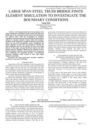
- 1. International Journal of Technical Research and Applications e-ISSN: 2320-8163, www.ijtra.com Volume 3, Issue 3 (May-June 2015), PP. 166-168 166 | P a g e LARGE SPAN STEEL TRUSS BRIDGE FINITE ELEMENT SIMULATION TO INVESTIGATE THE BOUNDARY CONDITIONS Liang Xiao Chongqing Jiaotong University Chongqing, China 475977598@qq.com Abstract—Overall gusset plate due to its advantages in the design, manufacture, installation, widely used in large span steel bridge, but for the whole gusset plate of local stress mechanism few scholars study. With the development of computer technology, often in practical projects through the finite element software to simulate, domestic scholars about the boundary conditions of the simulation is roughly divided into three kinds, that is, one end of the consolidation, center consolidation and simply supported at both ends, the principle of selecting the three boundaries often do not mention, for later users bring distress, In this paper, through theoretical analysis and finite element software simulation, illustrates the principle of three kinds of boundary selection, And according to the viewpoint of stress nephogram real simulation presents a recommended boundary conditions which formed at both ends simply supported constraints. Keywords—the whole gusset plate; boundary conditions; partial force; large span steel bridge I. INTRODUCTION Gusset plate is the main component of steel truss girder, the internal force of the main truss and deck system transfer through joints. Integral node of steel bar is the node plate with some chord welding as a whole, the main truss gusset plate to become box, better able to transfer internal force. The whole node board in terms of design, manufacture, installation, the advantages of make it widely used in long-span Bridges. About the calculation method of node plate, Whitmore first put forward the calculation method of bearing capacity of the node in the effective width method. Thornton, on the basis of introducing the column model, put forward the method for the bearing capacity of gusset plate buckling China steel structure specification separately considering the gusset plate under pull, pressure in different conditions. When the gusset plate under the tensile force of the web member came, usually along the most dangerous line tearing. And about the calculation of the whole gusset plate, little theoretical research at home and abroad, the analysis of the whole gusset plate is used mostly large general finite element software for numerical calculation. When using a finite element numerical simulation, using the beam element is usually the first full-bridge computing, and then to extract the whole gusset plate internal force, local stress analysis using shell elements. Extracted from the corresponding bar internal force to simulate the local stress, must ensure that local node plate the same force as a whole, so as to ensure the local analysis result is reliable. This article in domestic literature node selection of plate boundary conditions were analyzed, and points out its advantages and disadvantages, and put forward a persuasive boundary selection principle. II. THE DOMESTIC SCHOLARS ON THE BOUNDARY CONDITION OF THE WHOLE GUSSET PLATE SELECTION 1) The side of the gusset plate fixed form a statically determinate system. References 1 boundary conditions is the side of the gusset plate fixed form a statically determinate system; The selection of load: The main truss internal forces, internal forces in the form of web member nodal force is applied to the node board. Literature 2 is the same way for finite element simulation. 2) At the center of the gusset plate fixed to form statically determinate system. Would impose on node board member internal force model corresponding rod end. The internal forces of member bar is applied to the gusset plate model corresponding rod end. 3) Simply Supported constraints imposed on both ends of the rod main truss gusset plate on the formation of statically determinate system. The gusset plate at the corresponding internal forces rods extracted, applying the appropriate model in the gusset plates at bars, finite element simulation. As shown in Figure 1 (A) Fixed at one end (B) Center fixed (C) Simply supported on both ends Figure 1 Three select the form of the boundary III. ANALYSIS OF THREE KINDS OF THE INTEGRAL GUSSET PLATE BOUNDARY FORM 1) The selection of the boundary. The integral gusset plate as shown in figure 2, In the overall model Gusset A side, B-side, C and D-side bar will produce axial forces, shear forces and bending moments, at the same time, A, B, C, D terminal generates relative displacement. Through structural mechanics, the bearing displacement does not generate additional internal forces of statically determinate structure, at the same time after selecting statically determinate structure while they do not consider displacement difference of each bar in gusset plate, so the selection of statically determinate structure is reasonable. Figure 2 Overall gusset plate
- 2. International Journal of Technical Research and Applications e-ISSN: 2320-8163, www.ijtra.com Volume 3, Issue 3 (May-June 2015), PP. 166-168 167 | P a g e 2) The load applied. Most scholars in the selected statically determinate structure, directly extracted in full bridge rod internal forces applied at the corresponding position in the gusset plate model. According to the domestic scholars generally assume that, the overall model A, B, C, D terminal internal force is taken directly applied A, B, C, D terminal, the force applied at this time is the external force. At the same time after the external forces applied on the structure, can produce reaction at support. According to the structural mechanics, the internal forces in the same section is equal, can guarantee the member bar which internal forces are equal. The load directly at the end of member bar, Verification under three kinds of boundary conditions are the same as section internal force. In the span of simply supported beam under the action of concentrated force (Figure 3), Select segment which length L/5 distance from the right end is L/10, As shown in figure (a); Extract the main beam in the segment ends of the internal forces, As shown in figure (b). Now impose three kinds of boundary conditions is shown in figure 1, the calculated bearing reaction forces are zero, known the structure under concentrated load of each segment is self-balancing system. (a)midspan is applied concentrated force (b)Concerned cross-section internal force Figure 3 the figure of midspan is applied concentrated force In the span of simply supported beam under the action of bending moment (Figure 4), Select segment which length L/5 distance from the right end is L/10, As shown in figure (a); Extract the main beam in the segment ends of the internal forces, As shown in figure (b). Now impose three kinds of boundary conditions is shown in figure 1, the calculated bearing reaction forces are zero, known the structure under concentrated load of each segment is self-balancing system. (a)midspan is applied bending moment (b)Concerned cross-section internal force Figure 4 midspan is applied bending moment The gusset plate can be regarded as a horizontal beam, ventral pole of the internal forces can be equivalent to the mid- span section of the concentrated l forces and bending moment, Through the analysis of the figure 3, figure 4 shows simply supported beam under the action of concentrated force and bending moment are self-balancing system, So for the three gusset plate of the boundary conditions in the same section internal forces are the same. In summary: The three kind of boundary is shown in Figure 1 are statically determinate structure, And in three kinds of boundary conditions on the internal forces of the bar is self-balancing system, Therefore, three kinds of gusset plate boundary conditions are possible. IV. THROUGH THE FINITE ELEMENT SIMULATION RECOMMENDED BOUNDARY CONDITIONS ARE PRESENTED Using large bridge dedicated finite element software MIDAS/Civil establish the model shown in figure 5 for test beam. Test beam length 7m, high beam 0.63m. Top chord and lower chord use box section, The vertical member bar and Oblique abdominal rod use I-shaped cross-section. The whole beam is simulated with the beam element, Concerned node is Fourth gusset plate from right to left, Labeled Y 4 gusset plate. Impose the simple constraints on the two ends of the beam, Make it a simply supported system. Material selection for Q345 steel, Applied in 100KN size in the mid-span section direction downward concentrated force. Figure 5 MIDAS / Civil Model of test beam In the MIDAS/Civil model extracted Y4 gusset plate 1/2 rod end internal force , As shown in figure 6. Figure 6 Y4 Gusset plate rod end internal force distribution Using large bridge common finite element software Abaqus to Y4 gusset plate refine finite element analysis. Y4 gusset plate contains two horizontal chord, a vertical member bar and a oblique abdominal rod. Choosing a bar fully consider Saint-Venant principle, avoid Y3, Y5 gusset plate at the complex stress at the same time taking into account the boundary conditions and the gusset plate at a certain distance from the center to reduce the impact on the care of local boundary conditions at the gusset plate.Therefore, selection of chord, the web member and the vertical bar are half the length of each member bar. Because of the gusset plate in this load rating of steel did not enter the yield, so in Abaqus just input elasticity of the material properties not input plasticity, Modulus of elasticity of 2 × 10⁵MPa, Poisson's ratio is 0.3, Entire gusset plate using shell elements to model. Establish a reference point in the rod end of the center position, the reference point and the rod end coupling. The boundary and internal forces applied simultaneously at the reference point analog rod ends up boundaries and loading conditions. Model shown in Figure 7.
- 3. International Journal of Technical Research and Applications e-ISSN: 2320-8163, www.ijtra.com Volume 3, Issue 3 (May-June 2015), PP. 166-168 168 | P a g e Figure 7 Abaqus model diagram of Y4 Gusset plate After the application of the in Figure 1 (a) shown in boundary conditions for left end consolidation, Mises stress cloud shown in Figure 8, Because the load is applied at the border and stress concentration, where the analog distortion, so round the region to retain only concern gusset plate area. Figure 8 boundary one of a Mises stress nephogram (unit: MPa) After the application of the in Figure 1 (b) shown in boundary conditions for the center for consolidation, Mises stress cloud shown in Figure 9, Because the load is applied at the border and stress concentration, where the analog distortion, so round the region to retain only concern gusset plate area. Figure 9 boundary two of a Mises stress nephogram (unit: MPa) After the application of the in Figure 1 (c) shown in boundary conditions for the center for consolidation, Mises stress cloud shown in Figure 10, Because the load is applied at the border and stress concentration, where the analog distortion, so round the region to retain only concern gusset plate area. Figure 10 boundary three of a Mises stress nephogram (unit: MPa) From Figure 8 we can see in the boundary one (The left consolidation) at the maximum Mises stress appears in the Vertical web member on the left side, Its maximum value is 234.6 MPa. At the same time at different degrees of stress concentration phenomenon in the gusset plate fillet. From Figure 9 we can see in the boundary one (the center for consolidation) at the maximum Mises stress appears in the Vertical web member on the left side, Its maximum value is 234.6 MPa. At the same time at different degrees of stress concentration phenomenon in the gusset plate fillet. From Figure 10 we can see in the boundary one (Chord simply supported on both ends) at the maximum Mises stress appears in the Vertical web member on the left side, Its maximum value is 234.6 MPa. At the same time at different degrees of stress concentration phenomenon in the gusset plate fillet. Three kinds of boundary conditions at the same time the reaction are close to zero, thus satisfy the equilibrium conditions. V. CONCLUSION Through the above analysis, Three gusset plate boundary conditions (the left consolidation, the center for consolidation, chord simply supported on both ends) simulated maximum Mises stress both appear in the left vertical webs, and their values were about 234 MPa. By finite element analysis results further validate the results of the aforementioned. At the same time also shows that domestic scholars in the simulation the gusset plate boundary conditions three simulation ways are feasible It also shows that when Chinese scholars during the gusset plate boundary conditions simulated in three simulation methods are feasible. By three kinds of boundary conditions of stress nephogram indicates,although the maximum Mises stress appears has the same position, size, but the gusset plate stress distribution has obvious differences: There is a clear top gusset plate shear lag phenomenon when the left-consolidation; gusset plate at the center of significant stress concentration at the center of consolidation; Stress distribution constraint simply supported at both ends even when no obvious distortion region. So this article recommended the gusset plate simulate the boundary conditions was simulated through the formation of simply supported on both ends. REFERENCE [1] Guo z y. Stress analysis of the 108mm-span non-vertical bar steel truss integral gusset plate. China Communications Press, 2011, 236-263. [2] Chen y m, Tan y g, Wu y y. Local stress analysis of Si Du He steel truss girder gusset plates. [J]. Bridge Construction, 2008(1),58-61 [3] Mabsout. M. E. Tarhini. K., Frederick, G.R., and Tayar, C, Finite-element analysis of steel girder highway bridges. J. Bridge Eng., 1997, 2(3), 83-87. [4] Zhao t h, Lin m y. The steel bridge. China Communications Press, 2011, 263-275. [5] Ministry of communications of the people's Republic of China. (2004).General Code for Design of Highway Bridges and Culverts. China Communications Press. [6] Sullivan, S. R., Roberts-Wollmann, C. L., and Swenty, M.K, Composite behavior of precast concrete bridge deck-panel systems. PCI J. Summer, 2011, 43-59.