Design and Analysis of Articulated Inspection Arm of Robot

Nowadays Robot play a vital role in all the activities in human life including industrial needs. There is a definite trend in the manufacture of robotic arms toward more dexterous devices, more degrees of-Freedom, and capabilities beyond the human arm. The ultimate objective is to save human lives in addition to increasing productivity and quality of high technology work environments. The objective of this project is to design, analysis of a Generic articulated robot Arm. This project deals with the modeling of a special class of single-link articulated inspection arms of robot. These arms consist of flexible massless structures having some masses concentrated at certain points of hollow sections at the beam. Some aspects of the articulated Robot that are anticipated as useful are its small cross section and its projected ability to change elevation and maneuver over obstacle require large joint torque to weight ratios for joint actuation. A knuckle joint actions actuation scheme is described and its implementation is detailed in this project. The parts of the (AIA) arm are analyzed for deflection and stress concentration under loading conditions in different angles.

Recommended
More Related Content
What's hot
What's hot (20)
Viewers also liked
Viewers also liked (7)
Similar to Design and Analysis of Articulated Inspection Arm of Robot
Similar to Design and Analysis of Articulated Inspection Arm of Robot (20)
More from IJTET Journal
More from IJTET Journal (20)
Recently uploaded
Recently uploaded (20)
Design and Analysis of Articulated Inspection Arm of Robot
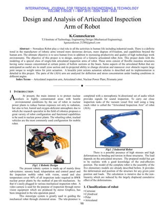
- 1. INTERNATIONAL JOURNAL FOR TRENDS IN ENGINEERING & TECHNOLOGY VOLUME 5 ISSUE 1 – MAY 2015 - ISSN: 2349 - 9303 98 Design and Analysis of Articulated Inspection Arm of Robot K.Gunasekaran T.J Institute of Technology, Engineering Design (Mechanical Engineering), kgunasekaran.25290@gmail.com Abstract— Nowadays Robot play a vital role in all the activities in human life including industrial needs. There is a definite trend in the manufacture of robotic arms toward more dexterous devices, more degrees of-Freedom, and capabilities beyond the human arm. The ultimate objective is to save human lives in addition to increasing productivity and quality of high technology work environments. The objective of this project is to design, analysis of a Generic articulated robot Arm. This project deals with the modeling of a special class of single-link articulated inspection arms of robot. These arms consist of flexible massless structures having some masses concentrated at certain points of hollow sections at the beam. Some aspects of the articulated Robot that are anticipated as useful are its small cross section and its projected ability to change elevation and maneuver over obstacle require large joint torque to weight ratios for joint actuation. A knuckle joint actions actuation scheme is described and its implementation is detailed in this project. The parts of the (AIA) arm are analyzed for deflection and stress concentration under loading conditions in different angles. Index Terms— Articulated inspection arm, Articulated robot, Nuclear Power Plant, Prismatic joint —————————— —————————— 1 INTRODUCTION At present, the main interest is to protect nuclear workers in highly contaminated areas with hostile environmental conditions by the use of robot in nuclear power plants to reduce human exposure not only to radiation, but also to hot, humid and oxygen-deficient atmosphere due to which the research specialist in the field of robotics proposes a great variety of robot configuration and functional capabilities to be used in nuclear power plants. The wheeling robot, tracked vehicles are the most commonly used configuration for mobile robot. Fig1. 1 Robotic Design The present robotic system is made up of mainly three sub-systems: sensory head; teleportation and control panel and the inspection mobile robot with vision, sound and also temperature cover 90% of all inspection tasks required in BWR nuclear power plants by the method of pan-tilt mechanism. So that it’s easily plugged in various mechanical inspection robot. A video camera is used for the purpose of inspection through stereo vision equipment which are produced by stereo Graphics, has been integrated in the tele-operation panel. This stereotype system is greatly used in guiding the mechanical robot through cloistered areas. The tele-presence is completed with a stereophonic bi-directional set of audio which provides signals for sound inspection. To carry out close inspection tasks of the vacuum vessel first wall using a long reach robot is called the ―Articulated Inspection Arm‖ of robot (AIA). Fig1. 2 Industrial Robot There is a possible presence of high stresses and high deformations in bending and torsion in these structures. The load depends on the articulated structure. The prepared model has got to be realistic with a good knowledge of the end-effectors position. The model of the complete robot is the assembly of the five elementary models are already described before. It provides the deformation and position of the structure for any given joint position and loads. The calculation is iterative due to the non- linearity which are induced by the largely displaced cumulative effect of the deformations. 1. Classifications of robot • Cartesian • Cylindrical • Polar • Articulated A
- 2. INTERNATIONAL JOURNAL FOR TRENDS IN ENGINEERING & TECHNOLOGY VOLUME 5 ISSUE 1 – MAY 2015 - ISSN: 2349 - 9303 99 • SCARA 1.2 Cartesian Robot Cartesian, or gantry, robot are defined by movement limited by three prismatic joints. The robot workspace is defined by a form of rectangular that results in the coincident axes. Fig1. 3 Cartesian Robot System 1.3 Cylindrical Robot If one of the Cartesian robot’s prismatic joints is exchanged for a revolute joint, a cylindrical robot is prepared. Its movement is defined by a cylindrical coordinate system. Fig1. 4 Cylindrical Robot System 1.4 Spherical Robot By trading of two prismatic joints with one revolute joints a spherical robot is formed. Spherical, or polar, robot are devices with a polar coordinate system. It works inside a thick shelled workspace which is in a spherical form, shown in figure 3. Fig1. 5 Spherical Robot System 1.5 Articulated Robot By substituting the revolute joint instead of final prismatic joint turns the arm into an articulated arm. Any robot whose arm has at least three rotary joints is considered to be an articulated robot (figure 4). The workspace is a complex set of intersecting spheres. Fig1.6 Articulated Robot System The above diagram shows the typical articulated robot. The articulated robot is used to fulfill some special applications. They lift heavy objects, painting, welding and also handle chemicals, thereby performing assembly work for days at a time without even suffering from fatigue as we humans do. Robot is defined by the nature of their movement. It can be seen that the required workspace weighs heavily in the selection of a robotic system. 1.6 SCARA Robot SCARA (which stands for Selectively Compliant Articulated Robot Arm) is Specialty robot in which there are two parallel rotational joints which provide compliance in a plane. A third prismatic joint allows the arm to translate vertically. SCARA robot differ from articulated robot in that its workspace consists of two concentric cylinders, demonstrated in figure 6.
- 3. INTERNATIONAL JOURNAL FOR TRENDS IN ENGINEERING & TECHNOLOGY VOLUME 5 ISSUE 1 – MAY 2015 - ISSN: 2349 - 9303 100 Fig1.7 SCARA Robot System This robot arm is specialized for assembly operations that involve placing parts on top of one another. The gripper can raise, lower, and rotate to orient the component to be assembled. 1.7 Robot Parts Fig1. 8 Parts of Robotic Arm Fig1. 9 Work cell Arrangements 1.8 MECHANICAL STRUCTURE This comprises all of the linkages and joints capable of movement. 1.9 ACTUATOR TYPES The necessity for proper selection of actuator will dictate how effective a robot is in performing a specific task. Actuators can be either mechanical or electrical and have varying strengths and weaknesses as demonstrated in table 1. The basic actuators used for controlling motion include: • Air Motors • Hydraulic Motors • Clutch/Brake • Stepper Motors Table 1.2: Actuator Comparison The most commonly used actuators in robotics consists of electric motors which can be either a stepper or servo type. The stepper motor performs well in an open loop systems whereas servomotors are best suited for applications in a closed loop system. 2. DESIGN OF EXPERIMENT 2.1 Design of Articulated Inspection Arm (AIA) The design calculations are formulated from strength of materials and from the Design of machine elements. The lengths of the AIAs are calculated considering the distance of the control panels for the core, the diameter of the core to be inspected and height of the core. Here the length is considered invariant with respect to required robot design. The two variants of cross sections considered are hollow square form and hollow circular form. Since the electrical and control system wiring to the various motors in the robotic assembly is subjected to pass through the hollow portion of the arm so we first consider both the inner and outer dimensions. CALCULATIONS Volume of the shaft, V V =π/4(do 2 - di 2 ) x Length Considering, k= di /do = 0.75 di = 0.75 do Volume, V= π/4 (do 2 -0.5625 do 2 ) x 4 V=1.37 do 2 m3 -- (1) Mass of the shaft, m Mass = volume x density =1.37do 2 x1.1x103 [ Considering, density of nylon = 1.1x10³ kg/m3 ] Mass, m=1507 do 2 -- (2)
- 4. INTERNATIONAL JOURNAL FOR TRENDS IN ENGINEERING & TECHNOLOGY VOLUME 5 ISSUE 1 – MAY 2015 - ISSN: 2349 - 9303 101 Force Acting On the Shaft, F Force, f=mass x acceleration due to gravity =1507 do 2 x 9.81 F= 14783.67 do 2 -- (3) Power of the motor, P P = (length of the shaft from the motor x speed of the motor x load acting) 60 P = 4x 10x14783.67 do 2 /60 P =9855.78 do 2 KW -- (4) Fig2. 1 Schematic Diagram of the Robot Arm Bending moment on the shaft occurs due to 1. Motor 2. Camera 3. Knuckle Joint 4. Weight of the shaft Bending moment, M =10x4(1+2+3+4+5) + (50x20) +20X2(1+3+5+7+9) +π/4(do 2 - di 2 ) x ρ x 2(1+3+5+7+9) M = 2600+75350 do 2 -- (5) Calculations based on Torsion: Equivalent Torsion, Te = Radius of gyration, K = = = K = 0.31 do -- (6) Column Factor, α = = 1 / 1-0.0044(4/.31do) = 0.31do/ (0.31do-0.0176) -- (7) Torque, T = (P x 60) / (2πN) = (9855.78 do 2 x 60) / 2π x 10 T = 9411.57 do 2 KN-m -- (8) Te= = -- (9) We also know that, Te = π/16 x τ do 3 x (1-k4 ) = π/16 x 7.5x109 x do 3 x 0.68 Te = 1.00138 x 10⁹ do 3 KN-m -- (10) Equating 9 & 10, we find that, do = 0.267 m ≈ 0.27 m di = 0.75 x 0.27 = 0.202 m ≈ 0.2 m Calculations based on bending moment: Me = ½[km x M + + Te =1/2[1.5 x (2600 + 75350 do 2 ) + + -- (11) And, Me= x σb (do 3 ) (1-k4 ) To find σb, = J= [do 4 - 0.31do 4 ] J=0.097 do 4 m4 Deflection (y) for nylon material would be 0.07 m for every 1 m length y=0.07 m σb = = 9411.57 do 2 x σb = 6791.85/ do 2 KN/m2 Me = x (do 3 ) (0.683) Me=455.41do -- (12) Equating 11 & 12, we get do = 0.298 m ≈ 0.3 m di = 0.75 x do = 0.75 x 0.3 = 0.225 m
- 5. INTERNATIONAL JOURNAL FOR TRENDS IN ENGINEERING & TECHNOLOGY VOLUME 5 ISSUE 1 – MAY 2015 - ISSN: 2349 - 9303 102 2.3. Modeling of AIA The AIA is modelled using a renowned 3D modeling software package known as Solidworks. The assembly is constructed for simulation of the robotic actions during working. The 3D model is further used for analyzing purpose in ANSYS. Fig2.2 Exploded view of Assembly AIA 2.2. Analysis of AIA: Analysis is carried out only for the base arm, since it is the major arm that handles all the other arms and connects the robot to the base. The following are the loads considered for analysis on the arm. Force due to the weight of the arms, joints, motors and camera Moment on the joint due to the weight of the arms, joints, motors and camera Torque due to the rotation of torsion motor located on the wrist of the arm Fig 2.3 FE model 4. RESULTS AND DISCUSSION Maximum displacements of hollow circular sections and rectangular sections consists of 26.638mm and 26.03mm during the first load step (while considering the position of the base arm is at 30 degrees). Considering the 4000mm arm length the deflection is 0.66% in the case of circular and 0.65% in the case of the rectangular section arm. It cumulates to a maximum of 159.83mm in circular and 156.18mm in rectangular section arm. It is only an elevated estimate because the bending moment along with the force acting on the arm will also decrease linearly (5-n) with the nth position of the five arms from the base arm. This deflection is negligible and can be controlled while programming the controller in more precise method. Therefore, both the Rectangular and Circular models are eligible for further studies. Comparison of Displacement sum of circular cross section and rectangular cross section AIA considering loads when the arm is at 300 . Comparison of Von Mises stress of circular cross section and rectangular cross section AIA considering loads when the arm is
- 6. INTERNATIONAL JOURNAL FOR TRENDS IN ENGINEERING & TECHNOLOGY VOLUME 5 ISSUE 1 – MAY 2015 - ISSN: 2349 - 9303 103 at 300 4.1 Comparison of Deflection of Circular & Rectangular C.S of AIA S. No Position of Arm in degree Deflection in mm Circular Rectangular 1 30 26.636 26.03 2 40 24.858 24.422 3 50 23.099 22.764 4.2 Comparison of stress distribution in Circular & Rectangular C.S of AIA S.No Position of Arm in degree Stress Circular Rectangular 1 30 4.641 4.345 2 40 4.86 4.331 3 50 4.881 4.318 5. CONCLUSION The Articulated Inspection Arm of Robot (AIA) is designed with the use of basic formulae from strength of materials and from the Design of machine elements. The two possible hollow cross sections i.e., (Rectangular section and Circular Sections) is modelled using commercially available 3D modelling tool known as SolidWorks and they are further studied and compared. The models are used for analysis with a commercially available analysis tool known as ANSYS by taking into account of various critical loads acting on the base of the robot arm alone. Since the base of the robot arm is the major component in which maximum magnitude of the critical loads are expected to occur, therefore it is enough to analyze the base of the robot arm alone. Considering the shapes, sizes, deflections during working and also stress occurs at both the AIAs are workable comparatively. Considering the manufacture, assembly weight and ease of transport, the circular section AIAs are preferred over the rectangular section AIAs. 6. REFERENCE [1] D. Arthur, Y. Perrot, C. Bidard et al. ITER Articulated Inspection Arm (AIA), Geometric Calibration Issues of a long – reach flexible robot. Fusion Engineering and Design75-79(2005) 543-546. [2] J.V.Miro, A.S.White, Modeling and industrial manipulator a case study, Simulation practice and theory, 9(2002) 293-319. [3] Leoncio Briones, Paul Bustmante, Miguel A.Serna, A Wall Climbing pneumatic robot for inspection in nuclear power plants, Robotics and computer integrated manufacturing, 0736- 5845(95)00005-4. [4] O.A.Barbian, W.Kappes, R.Neumann, H.K.Stanger, apparative developments for in-service inspection of reactor pressure vessels, Nuclear engineering and design 102(1987)341- 355. Author Profile: K.Gunasekaran is currently pursuing master’s degree program in Engineering Design in T.J Institute of Technology, Affiliated to Anna University, India, PH-09629890506. E-mail:kgunasekaran.25290@gmail.com.