Finite Element Analysis of Composite Patch Repairs

Adhesively-bonded patches are used for repair of different types of damages such as holes, notches, scratches, cracks etc. occurring in metallic as well as composite structures. The composite patching is the most widely used method of restoring the load-carrying capacity of the weakened structure. Due to the rapid growth of aerospace industry, analysis of adhesively-bonded patches to repair cracked structures have been the focus for many years. Most of these studies investigated repaired structures using linear analysis and demonstrated the viability of adhesively-bonded patch-repairs as a means to improve the durability and damage tolerance of cracked metallic structures efficiently and economically.Many researchers performed more intensive research on the method and presented the advantages of a composite material patch used for the cracked plate repairing. It was found that the bonded patch method not only reduces the weight but also increases the service life.In this research work, the analysis of cracked metallic and composite plates which are repaired by bonded-composite patches is performed using Finite Element Analysis package FRANC2D/L. This package is available with its corresponding mesh generating program CACSA. They are developed by Cornel Fracture Group, Cornel University.In this study, various fracture parameters for the structures are found out. It revealed that, the application of the bonded composite patches effectively reduces the stress intensity factor (SIF) near the crack tip and hence retards or eliminates the crack propagation. As the chances of fracture are almost reduced, the life of the structures increases by almost double of the initial. The main advantage of this patch repair technology is that, it doesn’t increase the weight of the structure too much.
![Ch. Ramakrishna.et al. Int. Journal of Engineering Research and Application www.ijera.com
ISSN : 2248-9622, Vol. 7, Issue 2, ( Part -2) February 2017, pp.10-18
www.ijera.com DOI: 10.9790/9622- 0702021018 11 | P a g e
B. Stress intensity factor (SIF)
The stress intensity factor, K, is used in
fracture mechanics to predict the stress state
("stress intensity") near the tip of a crack caused by
a remote load or residual stresses. It is a theoretical
construct usually applied to a homogeneous, linear
elastic material and is useful for providing a failure
criterion for brittle materials, and is a critical
technique in the discipline of damage tolerance.
The general equation used for calculation of SIF for
a rectangular plate with crack is,
K = σ (Π*a) ½
* f (a/w)
Where, σ = stress
a = semi-crack length
w = semi-plate width
f (a/ w)is a polynomial which depends on the
number of terms taken in the Taylorsexpansion.
Higher the number of terms more is the accuracy.
The general value of this term varies between 0.90
to 0.99.The SI unit of K is MPa√m.
C. Rose and Baker’s model for finding SIF for a
structure with patch
This is one of the very few analytical methods
available to find SIF for patched configuration.
According to it,Patch repaired SIF, KR is given by,
KR = Y.σ0√K
Where, Y= 1 for centre cracks and
σ0= σ/(1 + S)
s = Spring constant which depends on material
properties of the specimen and the patch.
III. FINITE ELEMENT ANALYSIS OF
COMPOSITE PATCH REPAIRED
CRACKED METALLIC PLATE
In this work, the analytical and numerical
analysis of centre cracked Aluminium plate[4, 10],
under the given loading and boundary conditions
are done. The analysis is carriedout for three
different configurations of the structure.
a) Un-patched or without patch configuration
b) Un-symmetric patch configuration
c) Symmetric patch configuration
The analytical analysis is carried out using
Rose and Baker’s model while the Finite Element
Analysis is done using package FRANC2D/L. The
mesh for this program is generated in CASCA
program. These two programs are available
simultaneously and developed by Cornell Fracture
Group, Cornell University. The FRANC2D/L
program runs on the specially designed algorithm
called Sahara-Fukoda.
A. The geometry of the problem
The following figure shows the geometry of the
problem.
Fig 2. The un-patched and patched configuration of
the Al plate
B. All properties of the plate, patch and adhesive
The dimensions, material properties and boundary
conditions of the Al plate are as given below.
Dimensions: 10 X 10 X 0.12 inch
Material Properties:
1. Young’s modulus, E = 70 GPa ,
2. Poisson’s ratio, ν = 0.33.
Boundary and loading conditions
1. Plate is simply supported at
lower edge.
2. A uniformly distributed load of
200 MPa (tensile) is applied at upper edge.
Original crack size of the centre crack, 2a
= 1 inch.
The material properties and the dimensions of the
patch are as given below.
Patch material: Carbon Fiber Reinforce
Plastic (CRPF)
Dimensions: 10 X 4 X 0.09 inch
Material properties,
1. Young’s moduli, E 1 = 135 GPa, E2 = E3 = 9
GPa
2. Poisson’s ratios, ν12 = ν13 = 0.3, ν23 = 0.02
3. Shear moduli, G12 = G13 = 5 GPa, G23 = 8 GPa
The properties of the adhesive used for the bond
between the patch and the plate are as given below.
Adhesive: Epoxy film adhesive, FM-73.
Young’s modulus: E = 2158 MPa
Shear modulus: G = 800 MPa
Poisson’s ration: 0.3
Thickness of the adhesive film: t = 0.006 inch.](data:image/gif;base64,R0lGODlhAQABAIAAAAAAAP///yH5BAEAAAAALAAAAAABAAEAAAIBRAA7)
Recommended
Recommended
More Related Content
What's hot
What's hot (18)
Viewers also liked
Viewers also liked (20)
Similar to Finite Element Analysis of Composite Patch Repairs
Similar to Finite Element Analysis of Composite Patch Repairs (20)
Recently uploaded
Recently uploaded (20)
Finite Element Analysis of Composite Patch Repairs
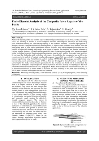
- 1. Ch. Ramakrishna.et al. Int. Journal of Engineering Research and Application www.ijera.com ISSN : 2248-9622, Vol. 7, Issue 2, ( Part -2) February 2017, pp.10-18 www.ijera.com DOI: 10.9790/9622- 0702021018 10 | P a g e Finite Element Analysis of the Composite Patch Repairs of the Plates Ch. Ramakrishna*1 , J. Krishna Balu2 , S. Rajashekar3 , N. Sivateja4 1, 2, 4 Assistant Professor, Department of Mechanical Engineering, KL University, Guntur, AP, India-522502. 3 Assistant Professor, Mechanical Department, KITS,Singapur Huzurabad, Karimnagar,TS- 505468 ABSTRACT: Adhesively-bonded patches are used for repair of different types of damages such as holes, notches, scratches, cracks etc. occurring in metallic as well as composite structures. The composite patching is the most widely used method of restoring the load-carrying capacity of the weakened structure. Due to the rapid growth of aerospace industry, analysis of adhesively-bonded patches to repair cracked structures have been the focus for many years. Most of these studies investigated repaired structures using linear analysis and demonstrated the viability of adhesively-bonded patch-repairs as a means to improve the durability and damage tolerance of cracked metallic structures efficiently and economically.Many researchers performed more intensive research on the method and presented the advantages of a composite material patch used for the cracked plate repairing. It was found that the bonded patch method not only reduces the weight but also increases the service life.In this research work, the analysis of cracked metallic and composite plates which are repaired by bonded-composite patches is performed using Finite Element Analysis package FRANC2D/L. This package is available with its corresponding mesh generating program CACSA. They are developed by Cornel Fracture Group, Cornel University.In this study, various fracture parameters for the structures are found out. It revealed that, the application of the bonded composite patches effectively reduces the stress intensity factor (SIF) near the crack tip and hence retards or eliminates the crack propagation. As the chances of fracture are almost reduced, the life of the structures increases by almost double of the initial. The main advantage of this patch repair technology is that, it doesn’t increase the weight of the structure too much. Keywords: Adhesively-bonded patches, Finite Element Analysis (FEA), Crackpropagation, Stress intensity factor (SIF). I. INTRODUCTION The objective of the adhesively bonded composite repair is to restore the damaged structure back to its original condition in terms of strength and stiffness. They restore the static strength and durability of the structure and decrease the high stresses caused by local damage in the form of cut outs, indentations, and cracks.The aim of this work is to review the capability of finite element models in estimating the mechanical behaviour of metallic and composite panels repaired by adhesively bonded composite patches. The interest in commercial finite element codes is due to their use in most of the industrial applications.So, after the application of bonded patches, we should be able to retard or eliminate crack growth, in metallic and composite structures. The aim is to determine the stress intensity near the crack tip, before and after the application of composite patch using Finite Element Package FRANC2D/L. Based on the results, necessary conclusions regarding bonded patch repair technology can be made. II. ANALYTICAL ASPECTS OF BONDED PATCH REPAIRS A. The adhesively bonded repairs The usual objective of a Bonded Repair is to restore the damaged structure back to its original condition in terms of strength and stiffness. The objectives of such repair work are to restore the static strength and durability of the structure and to decrease the high stresses caused by local damage in the form of cut outs, indentations, and cracks. The aim of this work is to review the capability of finite element models in estimating the mechanical behaviour of metallic panels repaired by composite patches.The interest in commercial finite element codes is due to their use in most of the industrial applications. Figure 1: Typical bonded patch arrangement over cracked specimen RESEARCH ARTICLE OPEN ACCESS
- 2. Ch. Ramakrishna.et al. Int. Journal of Engineering Research and Application www.ijera.com ISSN : 2248-9622, Vol. 7, Issue 2, ( Part -2) February 2017, pp.10-18 www.ijera.com DOI: 10.9790/9622- 0702021018 11 | P a g e B. Stress intensity factor (SIF) The stress intensity factor, K, is used in fracture mechanics to predict the stress state ("stress intensity") near the tip of a crack caused by a remote load or residual stresses. It is a theoretical construct usually applied to a homogeneous, linear elastic material and is useful for providing a failure criterion for brittle materials, and is a critical technique in the discipline of damage tolerance. The general equation used for calculation of SIF for a rectangular plate with crack is, K = σ (Π*a) ½ * f (a/w) Where, σ = stress a = semi-crack length w = semi-plate width f (a/ w)is a polynomial which depends on the number of terms taken in the Taylorsexpansion. Higher the number of terms more is the accuracy. The general value of this term varies between 0.90 to 0.99.The SI unit of K is MPa√m. C. Rose and Baker’s model for finding SIF for a structure with patch This is one of the very few analytical methods available to find SIF for patched configuration. According to it,Patch repaired SIF, KR is given by, KR = Y.σ0√K Where, Y= 1 for centre cracks and σ0= σ/(1 + S) s = Spring constant which depends on material properties of the specimen and the patch. III. FINITE ELEMENT ANALYSIS OF COMPOSITE PATCH REPAIRED CRACKED METALLIC PLATE In this work, the analytical and numerical analysis of centre cracked Aluminium plate[4, 10], under the given loading and boundary conditions are done. The analysis is carriedout for three different configurations of the structure. a) Un-patched or without patch configuration b) Un-symmetric patch configuration c) Symmetric patch configuration The analytical analysis is carried out using Rose and Baker’s model while the Finite Element Analysis is done using package FRANC2D/L. The mesh for this program is generated in CASCA program. These two programs are available simultaneously and developed by Cornell Fracture Group, Cornell University. The FRANC2D/L program runs on the specially designed algorithm called Sahara-Fukoda. A. The geometry of the problem The following figure shows the geometry of the problem. Fig 2. The un-patched and patched configuration of the Al plate B. All properties of the plate, patch and adhesive The dimensions, material properties and boundary conditions of the Al plate are as given below. Dimensions: 10 X 10 X 0.12 inch Material Properties: 1. Young’s modulus, E = 70 GPa , 2. Poisson’s ratio, ν = 0.33. Boundary and loading conditions 1. Plate is simply supported at lower edge. 2. A uniformly distributed load of 200 MPa (tensile) is applied at upper edge. Original crack size of the centre crack, 2a = 1 inch. The material properties and the dimensions of the patch are as given below. Patch material: Carbon Fiber Reinforce Plastic (CRPF) Dimensions: 10 X 4 X 0.09 inch Material properties, 1. Young’s moduli, E 1 = 135 GPa, E2 = E3 = 9 GPa 2. Poisson’s ratios, ν12 = ν13 = 0.3, ν23 = 0.02 3. Shear moduli, G12 = G13 = 5 GPa, G23 = 8 GPa The properties of the adhesive used for the bond between the patch and the plate are as given below. Adhesive: Epoxy film adhesive, FM-73. Young’s modulus: E = 2158 MPa Shear modulus: G = 800 MPa Poisson’s ration: 0.3 Thickness of the adhesive film: t = 0.006 inch.
- 3. Ch. Ramakrishna.et al. Int. Journal of Engineering Research and Application www.ijera.com ISSN : 2248-9622, Vol. 7, Issue 2, ( Part -2) February 2017, pp.10-18 www.ijera.com DOI: 10.9790/9622- 0702021018 12 | P a g e IV. GENERATION OF THE MESH USING CASCA Fig. 3: plate and patch mesh The CASCA program is used for generating mesh for the plate and the patch separately. One need to remember that, the common portion between the plate and patch, which is going to be bonded, should have the same structure of mesh. Otherwise, the Castofranc program will not merge the patch and plate meshes for the layered analysis. The bi-linear 4 sided elements are used. The above figures show the plate and patch meshes respectively. V. FEA USING FRANC2D/L A. Analysis of the cracked plate without patch The cracked plate with given boundary conditions and loading conditions, is simulated in FRANC2D/L using its meshed structure. The analysis is performed and various results such as deformed shape of the plate, crack tip stresses and SIF at the crack tip are obtained.The pictorial results are plotted as below. a) Deformed shape of the plate Fig. 4: deformed shape of the plate with enlarged view near the crack. b) Crack propagation simulation Fig. 5 a) simulation of crack propagation, b) SIF versus crack length c) Variation of σy for a semi crack size of 0.5 inch Following figure shows the variation of σy in the plate structures. The enlarged view of crack tip stresses is also shown. Fig. 6: variation ofσyin the plate structure for a = 0.5 inch.(All stresses are in psi) B. Analysis of the cracked plate with un- symmetric patch. A one sided CRPF patch called un- symmetric patch is applied on the patch over its top surface. The corresponding meshing of the patch is done. The meshes of plate and patch are merged using Castofranc program.Keeping all other conditions same, the FEA analysis of the plate with un-symmetric patch is carried out inFRANC2D/L and all the results are obtained as earlier, which are plotted below. The deformed shape of the plate is same as that of figure 4, but the deformation now is retarded by the presence of a patch. Hence the opening of the crack is reduced. The shape is not shown here for space constraints.
- 4. Ch. Ramakrishna.et al. Int. Journal of Engineering Research and Application www.ijera.com ISSN : 2248-9622, Vol. 7, Issue 2, ( Part -2) February 2017, pp.10-18 www.ijera.com DOI: 10.9790/9622- 0702021018 13 | P a g e a) Crack propagation simulation Fig. 7: Variation of SIF versus crack length for un- symmetric patch configuration. b) Variation of σy in the structure using un- symmetric patch Fig.8: Variation ofσyin un-symmetric patch configuration.(All stresses are in psi) C. Analysis of the cracked plate with symmetric patch configuration In this analysis, the patches of same dimensions are applied on both sides of the plate. So, the crack is now completely invisible. The patch that was earlier used on one side, is used on both sided now. Hence, the same mesh that was defined earlier is used for both patches along with plate, hence called as symmetric patch configuration. The plate mesh and two patch meshes are merged using Castofranc program. The common portion between patches and plate has same mesh structures.This analysis is carried out again in FRANC2D/L. The various fracture parameters, and property variations are found out, which are discussed below. The deformed shape of the plate is same as that of figure 4, but the deformation now is retarded more and more by the presence of two patches. Hence the opening of the crack is further reduced. The shape is not shown here for space constraints. a) Crack propagation simulation Fig. 9: Variation of SIF versus crack length using symmetric patch configuration. b) Variation of σy in the structure using symmetric patch configuration Fig. 10: variation ofσyand enlarged portion near the crack tip.(All stresses are in psi) VI. ANALYTICAL ANALYSIS OF THE PROBLEM As discussed earlier, the SIF is given by, K = σ (Π*a) ½ * f (a/w) There are different terms of f (a/ w) are available in the literature as well as SIF handbook. Here we chosen one of the most correct form of f (a/ w)using that SIF is given by,
- 5. Ch. Ramakrishna.et al. Int. Journal of Engineering Research and Application www.ijera.com ISSN : 2248-9622, Vol. 7, Issue 2, ( Part -2) February 2017, pp.10-18 www.ijera.com DOI: 10.9790/9622- 0702021018 14 | P a g e K1= σ.√ (∏a).[1.12 - 0.23 (a/2w) + 10.6 (a/2w)2 – 21.7(a/2w) 3 + 30.4(a/2w)4 ] This equation gives SIF for un-patched configuration. The results are obtainedand discussed in Results and discussions topic. VII. FINITE ELEMENT ANALYSIS OF A COMPOSITE PATCH REPAIRED,CRACKED LAMINATE In this chapter, the numerical analysis of the centre cracked graphite epoxy (Narmco ThornelT300/5208) laminate [9] under the given loading and boundary conditions are done. The analysisis carried out for only symmetric patch configuration.The Finite Element Analysis is done using package FRANC2D/L. The mesh for this program is generated in CASCA program. These two programs are available simultaneously and developed by Cornell Fracture Group, Cornell University. The FRANC2D/L program runs on the specially designed algorithm called Sahara- Fukoda. A. The geometry of the problem Fig. 11: Geometry of the problem B. All properties of the problem Material properties of the plate. The basic ply is made up of a graphite-epoxy (Narmco Thornel T300/5208), which havefollowing properties. Young’s moduli, E 1 = 141 GPa and E1/E2 = 14.96 Shear modulus, G = 5.18 GPa Poisson’s ratio, ν12 = 0.31 Dimensions of the laminate and a crack The centrally located crack is of length 160 mm in a graphite epoxy laminate having dimensions of 800 mm X 800 mm x 3 mm. The moduli of the panel were taken to be as for a symmetric lay up of (O/90)s. Dimensions of the patch A symmetric patch configuration is assumed for the panel. The patch dimensions are 320 mm x 320 mm x 1 mm. The size and shape of the patch are selected according to the Baker’s recommendations. He suggests that, the length of the patch should not be more than twice of the crack length. Adhesive properties The adhesive material used is Epoxy-film adhesive FM-73. Young’s modulus, E = 2158 MPa, Shear modulus, G = 800 MPa, Poisson’s ratio, ν = 0.35, Thickness of the adhesive film, t = 0.2 mm VIII. GENERATION OF THE MESH FOR LAMINATE AND THE PATCH Fig 12:a) laminate mesh and b) patch mesh The laminate is to be applied with symmetric patch. Hence, we need to design the meshes of the two patches exactly the same as that of the common are covered by laminate and patches. The meshes are generated in CASCA program, separately for patch and plate. The bi- linear 4 sided elements are used for the meshes. Later they are merged using Castofranc program in order to use in the FRANC2D/L. Above figure shows the mesh structures of the laminate and the patches. IX. FEA WITHOUT PATCH IN FRANC2D/L After generating the mesh in CASCA, the mesh is transferred to FRANC2D/L for FEA analysis. By giving all the inputs related to properties and other conditions, the analysis is run. The results are obtained in terms of plots and some fracture parameters are also obtained. A. Deformed shape of the laminate without patch, Variation of σy in the laminate and around the crack tip
- 6. Ch. Ramakrishna.et al. Int. Journal of Engineering Research and Application www.ijera.com ISSN : 2248-9622, Vol. 7, Issue 2, ( Part -2) February 2017, pp.10-18 www.ijera.com DOI: 10.9790/9622- 0702021018 15 | P a g e Fig 13:a) Deformed shape of the laminate without patch b) Variation ofσyin the laminate and around the crack tip B. Analysis of the problem using symmetric patch configuration Fig 13:a) deformed shape with symmetric patches b) σyvariation in laminate with symmetric patches X. THE STATEMENT OF THE PATCH REPAIR PROBLEM FOR AN EDGE CRACKED LAMINATE The above problem is analyzed again for an edge crack, instead of centre crack. All otherproperties and dimension of the plate, patch and adhesives are kept unchanged. The initial cracksize is also same and it is 160 mm. A. Geometry of the problem Fig 14: The geometry of the edge crack problem B. All properties of the problem The change in the current problem and the problem in section VII-B is that, the centre crack is replaced with edge crack. All other parameters are unchanged. XI. GENERATION OF THE MESH FOR THE LAMINATE AND THE PATCH The same procedure is applied as described in section VIII and the meshes for the laminate and the patch are obtained as below. Figure 15:a) laminate mesh and b) patch mesh XII. FEA WITHOUT PATCH IN FRANC2D/L The same procedure, as explained in section IX is applied in FRANC2D/L and the results are plotted as shown in below. A. Deformed shape of the laminate without patch and Variation of σy in the laminate and around the crack tip Fig 16: a) deformed shape of the laminate without patch b) Variation of σy in the laminate and around the crack tip
- 7. Ch. Ramakrishna.et al. Int. Journal of Engineering Research and Application www.ijera.com ISSN : 2248-9622, Vol. 7, Issue 2, ( Part -2) February 2017, pp.10-18 www.ijera.com DOI: 10.9790/9622- 0702021018 16 | P a g e B. Deformed shape with symmetric patches and σy variation in laminate with symmetric patches Fig 17:a) deformed shape with symmetric patches b) Variation of σy in the laminate with symmetric patches XIII. RESULTS AND DISCUSSION A. Results for patch repair of the aluminium (Al) plate from section III: Various parameters are found out in the analysis carried out in section III. The results are as presented below in the tabular format. Results for SIF found by various methods for an initial crack size of a = 0.5 inch, all values are in psi σinch. Configurat ion SIF (experimen tal) (psi σinch) SIF (analytic al) (psi σinch) SIF (psi σinch) Percent age error Without patch 0.372E5 0.363E5 0.3679 E5 3.6 With un- symmetric patch 0.212E5 0.189E5 0.20E5 3.3 With symmetric patch 0.148E5 0.135E5 0.14E5 3.7 Table 1: SIF found by various methods for cracked Al plate. Crack tip stresses (σy) for all cases Form the above table it is seen that, the crack tip stresses reduce with the application of the patches. Hence, the SIF at the tip reduces and crack growth can be avoided. Table 2: Crack tip stresses (σy) for all cases Configuration σyat the crack tip using FEA (psi) Without patch 1.41E5 With un-symmetric patch 0.782E5 With symmetric patch 0.581E5 Effect of the thickness of the patch on SIF Thickness of the patch (inch) SIF using FEA (psi σinch) Percentage reduction 0.03 0.20E5 - 0.06 0.168E5 15 0.09 0.1484E5 12 Table 3: Effect of the thickness of the patch on SIF Effect of patch shape on the SIF Shape of the patch SIF using FEA (psiσinch) Symmetric, rectangular 0.1484 E5 Symmetric, elliptic 0.213 E5 Symmetric, circular 0.256 E5 Table 4: Effect of the patch shape on the SIF From the above table, it is seen that, the rectangular patch gives the least SIF, while circular patchgives the highest SIF. Hence, rectangular p the rectangular patch is most advantageous of all theshapes of patches. B. Results for the patch repair of the centre cracked graphite-epoxy laminate from section VII The Finite Element Analysis of the cracked graphite-epoxy laminate is done in FRANC2D/L. The crack tip stresses are found out along with SIF for various values of crack sizes. The analysis is done for two configurations, un-patched and symmetric patch cases. Crack tip stresses (σy) Configuration σyfor 2a = 160 mm (MPa) σyfor 2a = 200 mm (MPa) σyfor 2a = 240 mm (MPa) Without patch 976.8 1120.2 1255.6 With symmetric patch 326.9 448.5 582.5 Stress intensity factor (SIF) Configuration SIF for 2a = 160 mm (MPa√mm) SIFfor 2a = 200 mm (MPa√mm) SIF for 2a = 240 mm (MPa√mm) Without patch 618.7 730.5 849.6 With symmetric patch 92.8 131.5 186.9 Stress intensity factor ratio (R) Some of the literatures take into consideration the ratio of SIF with patched configuration to the SIF with un-patched configuration. This ratio is called as stress intensity factor ratio (R). It is a measure of the efficiency of the patch. The calculated values of R are shown in the following table. Also, the initial value of R is compared with the literature value.
- 8. Ch. Ramakrishna.et al. Int. Journal of Engineering Research and Application www.ijera.com ISSN : 2248-9622, Vol. 7, Issue 2, ( Part -2) February 2017, pp.10-18 www.ijera.com DOI: 10.9790/9622- 0702021018 17 | P a g e Crack size, 2a (mm) ‘R’ from literature ‘R’ from FEA Percentage error 160 0.140 0.147 5 200 - 0.178 - 240 - 0.212 - From the above analysis of SIF ratio using FEA, it is seen that, SIF at the crack tip is reduced by almost 78-85% of the initial value. It is an extremely important conclusion and justifies the use of bonded composite patch repairs. C. Results for the patch repair of the edge- cracked graphite-epoxy laminate from section VII The Finite Element Analysis of the edge-cracked graphite-epoxy laminate is done in FRANC2D/L. The crack tip stresses are found out along with SIF for various values of crack sizes. The analysis is done for two configurations, un-patched and symmetric patch cases. Crack tip stresses (σy) Configuration σyfor 2a = 160 mm (MPa) σyfor 2a = 200 mm (MPa) σyfor 2a = 240 mm (MPa) Without patch 1016 1250.6 1405.9 With symmetric patch 448.2 564.8 695.5 Stress intensity factor (SIF) Configurati on SIF for 2a = 160 mm (MPa√m m) SIF for 2a = 200 mm (MPa√m m) SIF for 2a = 240 mm (MPa√m m) Without patch 730.6 845.1 960.4 With symmetric patch 205.1 278.9 355.3 Stress intensity factor ratio (R) Crack size, 2a (mm) ‘R’ from FEA 160 0.28 200 0.33 240 0.37 From the above analysis of SIF ratio using FEA, it is seen that, SIF at the crack tip is reduced by almost 60-70% of the initial value. It is an extremely important conclusion and justifies the use of bonded composite patch repairs. XIV. CONCLUSION Following important conclusions are made in this analytical study of adhesively-bonded composite patch repairs. 1. The most important conclusion drawn from the study is that, the use of bonded composite patches reduces the SIF and crack tip stresses by very large amount. Therefore, it retards or eliminates the crack growth which eventually avoids fracture.The service life of the material can be increased up to twice of the initial. 2. Among the various shapes of the bonded patches, the rectangular patches are most efficient as they reduce the SIF by highest amount.As the thickness of the patch increases, the SIF decreases. 3. The symmetric patch configuration is the most efficient over un-symmetric because, it reduces the SIF by highest value. The adhesively- bonded composite repairs are the easiest, efficient way of repairing damages in structures. 4. These bonded composite repairs can be regarded as a versatile cost-effective method of repairing, strengthening or upgrading inadequate metallic structures. The reinforcements or patches are ideally implemented, avoiding the need for costly disassembly of built-up structures. 5. CASCA and FRANC2D/L are very easy and user friendly FEA packages. They have many advantages such as; the layer-wise analysis of 3-D structure can be done assuming each layer in plane stress conditions. It simplifies the analysis, with much greater accuracy. 6. Finite Element Analysis is the easiest way of finding approximately accurate primary results. They are advantageous over analytical and experimental work in this regard. Hence, it is used vastly in industrial applications. REFERENCES [1]. Ong C. L., Shen S.B., “The reinforcing effect of composite patch repairs on metallicaircraft structures”, Aero industry development centre, Taiwan, China, 1991. [2]. Baker A. A., “Fibber composite repair of cracked metallic aircraft components – practicaland basic aspects”, composites, volume 18, No .4, 1987. [3]. Baker A. A., “Repair of cracked or defective metallic aircraft components with advancedfibre composites- an overview of Australian work”, composite structures 2 (1984) 153-181. [4]. Mahadesh Kumar A., Hakeem S. A., “Optimum design of symmetric composite patchrepair to centre cracked metallic sheet”, Aircraft Research and Design Centre, HindustanAeronautics Limited, Design Complex, Bangalore. [5]. Ramji M., Mohammed K., “Design of optimum patch shape and size for bonded repairon damaged
- 9. Ch. Ramakrishna.et al. Int. Journal of Engineering Research and Application www.ijera.com ISSN : 2248-9622, Vol. 7, Issue 2, ( Part -2) February 2017, pp.10-18 www.ijera.com DOI: 10.9790/9622- 0702021018 18 | P a g e carbon fiber reinforced polymer panels”, materials and design –54(2014)174-153. [6]. Baker, A.A., Chester, R.J., Davis, M.J., “Reinforcement of the F-111 wing pivot fittingwith a boron/epoxy doubler system - materials engineering aspects”. Composites, 24, pp.51 1-521, 1993). [7]. Anderson T. L., “Fracture Mechanics – Fundamentals and Applications, 3rdEdition”,Taylor and Francis Group, 2005. [8]. Bartholomeusz, R.A., Baker, A.A., Chester, R.J., “Bonded joints with through thicknessadhesive stresses - reinforcing the F/A-18 Y470.5 Bulkhead”, Int. J. of Adhesion and Adhesives, 19,pp. 173-180, 1999. [9]. Jonnes R., Callinan R., Aggarwal K, “Analysis Of Bonded repairs to damaged fibercomposite structures”, Vol. 17, pp-37-46, 1983. [10].Ricci F., Francesco F., “Bonded Composite Patch repairs on cracked aluminiumplates: “Theory, modelling and experiments”, Advances in composite materials- 2011. AUTHOR PROFILE Ch. Ramakrishna pursued his M.Tech from JNT University, Hyderabad. He has been working presently as an Assistant Professor, Department of Mechanical Engineering, KL University, and Guntur, India-522502. J. Krishna Balu pursued his M.Tech from IIT Madras. He has been working presently as an Assistant Professor, Department of Mechanical Engineering, KL University, and Guntur, India- 522502. Eswara Kumar.A pursued his M.Tech from VR Siddhartha to JNTU Kakinada. He has been working presently as an Assistant Professor, Department of Mechanical Engineering, KL University, and Guntur, India-522502.