Design and stress analysis of broach tool for splines

Broaches are used for machining either internal or external surface (i.e. sizing of holds and cutting of serrations, straight or helical planes, gun rifling and key ways). In this work a broach cutting tool is design to perform internal splines of synch shuttle transmission for flange coupling. Broaching is a machining process in which a cutting tool, having multiple transverse cutting edges, is pushed or pulled through a hole or surface to remove metal by axial method. It is capable of production rates as much as 25 times faster than any traditional metal removing methods In this work a broach cutting tool is design to perform internal splines on sleeve main shaft. A sophisticated ANSYS 11 (FEM) package shall be used to analyze the displacements and stresses present in broach cutting tool. Further the solid model can be used to perform the finite element analysis which would help in knowing the characteristic of the broach tool under various cutting loads.

Recommended
Recommended
More Related Content
What's hot
What's hot (18)
Viewers also liked
Viewers also liked (20)
Similar to Design and stress analysis of broach tool for splines
Similar to Design and stress analysis of broach tool for splines (20)
Recently uploaded
Recently uploaded (20)
Design and stress analysis of broach tool for splines
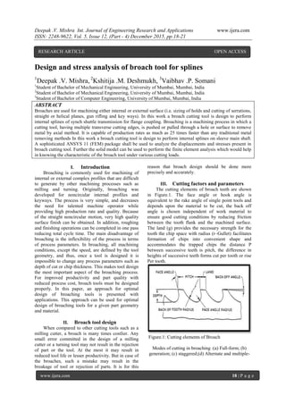
- 1. Deepak .V. Mishra Int. Journal of Engineering Research and Applications www.ijera.com ISSN: 2248-9622, Vol. 5, Issue 12, (Part - 4) December 2015, pp.18-21 www.ijera.com 18 | P a g e Design and stress analysis of broach tool for splines 1 Deepak .V. Mishra, 2 Kshitija .M. Deshmukh, 3 Vaibhav .P. Somani 1 Student of Bachelor of Mechanical Engineering, University of Mumbai, Mumbai, India 2 Student of Bachelor of Mechanical Engineering, University of Mumbai, Mumbai, India 3 Student of Bachelor of Computer Engineering, University of Mumbai, Mumbai, India ABSTRACT Broaches are used for machining either internal or external surface (i.e. sizing of holds and cutting of serrations, straight or helical planes, gun rifling and key ways). In this work a broach cutting tool is design to perform internal splines of synch shuttle transmission for flange coupling. Broaching is a machining process in which a cutting tool, having multiple transverse cutting edges, is pushed or pulled through a hole or surface to remove metal by axial method. It is capable of production rates as much as 25 times faster than any traditional metal removing methods In this work a broach cutting tool is design to perform internal splines on sleeve main shaft. A sophisticated ANSYS 11 (FEM) package shall be used to analyze the displacements and stresses present in broach cutting tool. Further the solid model can be used to perform the finite element analysis which would help in knowing the characteristic of the broach tool under various cutting loads. I. Introduction Broaching is commonly used for machining of internal or external complex profiles that are difficult to generate by other machining processes such as milling and turning. Originally, broaching was developed for noncircular internal profiles and keyways. The process is very simple, and decreases the need for talented machine operator while providing high production rate and quality. Because of the straight noncircular motion, very high quality surface finish can be obtained. In addition, roughing and finishing operations can be completed in one pass reducing total cycle time. The main disadvantage of broaching is the inflexibility of the process in terms of process parameters. In broaching, all machining conditions, except the speed, are defined by the tool geometry, and thus, once a tool is designed it is impossible to change any process parameters such as depth of cut or chip thickness. This makes tool design the most important aspect of the broaching process. For improved productivity and part quality with reduced process cost, broach tools must be designed properly. In this paper, an approach for optimal design of broaching tools is presented with applications. This approach can be used for optimal design of broaching tools for a given part geometry and material. II. Broach tool design When compared to other cutting tools such as a milling cutter, a broach is many times costlier. Any small error committed in the design of a milling cutter or a turning tool may not result in the rejection of part or the tool. At the most it may result in reduced tool life or lesser productivity. But in case of the broaches, such a mistake may result in the breakage of tool or rejection of parts. It is for this reason that broach design should be done more precisely and accurately. III. Cutting factors and parameters The cutting elements of broach teeth are shown in Figure.1. The face angle or hook angle is equivalent to the rake angle of single point tools and depends upon the material to be cut, the back off angle is chosen independent of work material to ensure good cutting conditions by reducing friction between the tooth flank and the machined surface. The land (g) provides the necessary strength for the tooth the chip space with radius (r–Gullet) facilitates formation of chips into convenient shape and accommodates the trapped chips the distance P between successive teeth is pitch, the difference in heights of successive teeth forms cut per tooth or rise Per tooth. Figure.1: Cutting elements of Broach Modes of cutting in broaching :(a) Full-form; (b) generation; (c) staggered;(d) Alternate and multiple- RESEARCH ARTICLE OPEN ACCESS
- 2. Deepak .V. Mishra Int. Journal of Engineering Research and Applications www.ijera.com ISSN: 2248-9622, Vol. 5, Issue 12, (Part - 4) December 2015, pp.18-21 www.ijera.com 19 | P a g e sided Figure.2: Design for chip space in a broach IV. Design procedure Proper observation of the component drawing leads us to the following data: Major Dia. D = 20 mm Minor Dia. d = 16 mm No. of splines S = 6 Spline width W = 4.0 + 0.01 mm Length of the splines I = 60 mm Hardness = 35 HRC Table 4.1 V. Broaching tool design for internal splines Results: Input data Output data The rake angles of tool for 12°, 15° and 18° and pitch of 9.68 mm, 10.457 mm and 11.23 mm are considered for various values of depth of Cut (rise / tooth), the values of length of the tool over teeth, total length of the tool, specific cutting force, total Broaching force and load per tooth were recorded with the help of „C‟ program and the results are tabulated. Figure.4: Variation of specific cutting force Vs. Rise/Tooth Figure.5: Variation of Total broaching force Vs. Rise/ Tooth
- 3. Deepak .V. Mishra Int. Journal of Engineering Research and Applications www.ijera.com ISSN: 2248-9622, Vol. 5, Issue 12, (Part - 4) December 2015, pp.18-21 www.ijera.com 20 | P a g e Figure.6: Variation of Total broaching force Vs. Rise/tooth Figure.7: Variation of total broaching force Vs. Rise/tooth VI. STRESS DISTRIBUTION AND NODAL DISPLACEMENT USING FINITE ELEMENT ANALYSIS Figure.8: Cutting tooth with Finite elements Figure.9: 1st Principle stress distribution S1 The below table shows rise/tooth mm, load/tooth, stress SX, stress SY, stress SXY, stress S1, stress S2, N/mm2 and deflection, mm for rake angle 15°,12° and 18°.
- 4. Deepak .V. Mishra Int. Journal of Engineering Research and Applications www.ijera.com ISSN: 2248-9622, Vol. 5, Issue 12, (Part - 4) December 2015, pp.18-21 www.ijera.com 21 | P a g e Below are the variations of stresses SX, SY with respect to Rise/tooth Figure:10: Variation of stress SY Vs. Rise/tooth Figure:11: Variation of stress SX Vs. Rise/tooth VII. Conclusion The variation of cutting force per tooth is constant for different pitch values, for a given rake-angle. The total Broaching force varies with pitch value for a given rake angle due to the variations in number of teeth in engagement. The stress plot against depth of cut shows uniform increase of stresses, the stresses are increasing with decreasing of rake angles due to higher cutting forces. The deflection of the tooth is higher for higher rake angle. This is because of the reduction in included angle of the tooth. The rake angle influencing the total broaching force and force on cutting tooth. Hence very care should be taken while re-sharpening the tooth tool to maintain the designed rake angle on the profile of the tooth. References [1] U Kokturk, E. Budak , “Optimization of Broaching Tool Design” Inteligent Computation in Manufacturing Engineering - 4261- 4273. [2] S.P.Mo,D.A.Axinte,T.H.Hyde,N.N.Z.Gindy, “An example of selection of the cutting conditions in broaching of heat resistance alloy based on cutting forces, surface roughness and tool wear”, Journal of Material Processing Technology, Vol 160 pp.382- 389,2005. [3] Dragas A. Axinte, “Approach into the use of Probabilistic neural networks for automated classification of tool malfunctioning in broaching”, [4] International Journal of Machine Tools and and Manufacture 46 (2006) 1445-14484. Yuan Yuefeng,Chen Wuyi,Gao Liansheng, “Tool Materials Rapid Selection Based on Initial Wear” ,Chinese Journal of Aeronautics,23(2010)386- 382 [5] E.A .Markin “Investigation of the hydro- mechanical system of broaching machine”, Journal of Machine tools and manufacture Vol 37 pp 11-15,1966. [6] Drozda, J.T., 'Broaching Planning, Shaping and Slotting', Tool and Manufacturing Engineering Handbook, Vol. 1, Mcfiraw-Hill, 1983. [7] Juvinall, R. C., Stress, Strain and Strength, Mcflraw Hill, 1982. [8] Collins, J.A., 'Failure of Material in Mechanical Design', Analysis prediction prevention, John Wiley and sons, 1981. [9] Engineering Modeling System, Reference Manual, Intergraph Corporation, 1994. [10] Finite Element Modeler, Operators Training Guide, Intergraph Corporation, 1994. [11] Hindustan Machine Tools limited, Production technology, Tata McGraw Hill, New Delhi, 1987. [12] Zeid, I., CAD/CAM Theory and Practice, McGraw- Hill, 1991. [13] Burden, W., Broaches and Broaching, Broaching Tool Institute, 1944.