Download to read offline
![International Research Journal of Engineering and Technology (IRJET) e-ISSN: 2395-0056
Volume: 03 Issue: 01 | Jan-2016 www.irjet.net p-ISSN: 2395-0072
© 2016, IRJET ISO 9001:2008 Certified Journal Page 173
II. LITERATURE REVIEW
[01].Tasdemir et al. (2008) applied ANN to
predict surface roughness a turning process.
This method was found to be quite effective
and utilizes fewer training and testing data.
[02] Hazim et.al (2009) developed a surface
roughness model in end milling by using
Swarm Intelligence. From the studies, data was
collected from CNC cutting experiments using
Design of Experiments approach. The inputs to
the model consist of Feed, Speed and Depth of
cut while the output from the model is surface
roughness. The model is validated through a
comparison of the experimental values with
their predicted counterparts.
[03].Benardos & Vosniakos presented various
methodologies and practices that were
employed to predict surface roughness. The
approaches listed in their review paper were
classified into those based on machining
theory, experimental investigation, designed
experiments, and artificial intelligence.
[04].Choudhury et al. discussed the
development of surface roughness prediction
models for turning EN 24T steel (290 BHN)
using a response surface methodology. A
factorial design technique was used to study
the effects of the main cutting parameters such
as cutting speed, feed, and depth of cut on
surface roughness. The tests were carried out
using uncoated carbide inserts without any
cutting fluid.
[05] V. Pallavi, Anoop kumar and T. Mohandas
(2012). Optimization of turning parameters for
surface roughness using taguchi method.
International Journal of Mechanical
Engineering. Vol. 5 : Issue 2.
[06] Surinder kumar, Meenu and P.S. Satsangi
(2012). A genetic algorithmic approach for
optimization of surface roughness prediction
model in turning using UD-GFRP composite.
Indian Journal of Engineering and Materials
Sciences. Vol. 19, 386-396.
[07] Reddy et al.performing experiment for
optimized the parameter for MRR using
Taguchi methodology and ANOVA. The L9
Orthogonal array is used in MINITAB 15 which
shows the percentage contribution of each
influencing factor on MRR.The material used
for the experiment is (100 x 34 x 20 mm)
blocks of aluminium cast heat-treatable alloy.
[08] Yang et al. studied the surface roughness
on end milling with gene expression
programming. In this research, a method based
on gene expression programming (GEP) has
been proposed to construct the prediction
model of surface roughness. GEP combines the
advantages of the genetic algorithm (GA) and
genetic programming (GP).
[09] Chockalingam et al. studied the effect of
different coolant conditions on milling of AISI
304 stainless steel.Cooling methods used in this
investigation were flooding of synthetic oil,
water-based emulsion, and compressed cold
air. Cutting forces and the surface roughness
were studied and tool flank wears observed. In
this study, the comparison between different
coolants effect to the milling of AISI 304
stainless steel is done.
[10] Routara et al.[investigated the
optimization of parameters using response
surface method. For this research three
different materials 6061-T4 aluminium, AISI
1040 steel and medium leaded brass UNS
C34000 were used. For this research he used
the ANOVA approach and F test.
[11] Thakkar et al.[optimized of Process
Parameters for Surface Roughness and Material
Removal Rate for SS 410 Material. All
experiment conduct on CNC turning and the
output parameters are MRR & SR is predicted
by ANOVA.
MACHINING PARAMETERS AFFECTS THE
SURFACE ROUGHNESS
Cutting speed and cutting feed: The process of
metal cutting or machining of metal work-piece
is influenced greatly by the relative velocity
between the work-piece and the edge of the
cutting tool. The relative movement in the
machining operations is produced by the](https://image.slidesharecdn.com/irjet-v3i130-171014110911/75/Analysis-of-Surface-Roughness-for-Cylindrical-Stainless-Steel-Pipe-Ss-3163-In-CNC-Lathe-Turning-Process-Using-ANN-Method-2-2048.jpg)
![International Research Journal of Engineering and Technology (IRJET) e-ISSN: 2395-0056
Volume: 03 Issue: 01 | Jan-2016 www.irjet.net p-ISSN: 2395-0072
© 2016, IRJET ISO 9001:2008 Certified Journal Page 174
combination of rotary and translator
movement either of the work-piece or of the
cutting tool or both. The presence of these
motions e.g., feed and cutting speed permits the
exertion of the process of cutting continuously.
In machine tools with rotary priming cutting
motion, the cutting speed is given by:
V = πDN m/min.
1000 where D is diameter of the milling cutter
(mm) N is the cutter rotational speed in rpm.
Surface roughness is an important measure of
product quality since it greatly influences the
performance of mechanical parts as well as
production cost. Surface roughness has an
impact on the mechanical properties like
fatigue behaviour, corrosion resistance, creep
life, etc. It also affects other functional
attributes of parts like friction, wear, light
reflection, heat transmission, lubrication,
electrical conductivity, etc. Sometimes, various
catastrophic failures causing high costs have
been attributed to the surface finish of the
components in question. As a result, there have
been a great many research developments in
modelling surface roughness and optimization
of the controlling parameters to obtain a
surface finish of desired level since only proper
selection of cutting parameters can produce a
better surface finish
III. EXPERIMENTAL METHODOLOGY FOR SS
316L PIPE
The specimens of 316LStainless Steel pipe used
for experimentation of the following Table
shows nominal and actual composition of 316L
SS used for the study. It was subjected to
turning operation which was carried out on
Lathe Machine. [1]As 316 LSS is a hard
material, carbide tool was selected .Carbide
leaves a better finish on the part and allows
faster machining. Carbide tools can also
withstand higher temperatures than standard
high speed steel tools. [3] Cylindrical specimen
of 12 cm diameter was safely turned in the four
jaw chuck by supporting the free end of the
work. If work piece is quite long it needed to
face and centre drill the free end supported by
the tailstock. Without such support, the force of
the tool on the work piece would cause it to
bend away from the tool, producing a strangely
shaped result. [4]Traditionally design methods
are too complex and difficult to use. A large
number of experimental works has been done
when the process parameters are increased
with their levels. To solve this problem BY
using specific parameters with a design of
orthogonal arrays to study the all parameters.
Taguchi Method is developed by Dr.Genichi
Taguchi, a Japanese quality management
consultant. [6] It is an efficient tool for the
design of high quality manufacturing system.
The main advantage of this method to reduce
the experimental time and find out significant
factor. [9]Taguchi robust design method is a
most powerful tool for the design of a high
quality system. He considered three steps in a
process’s and product’s development: system
design, parameter design, and tolerance design.
In system design, the engineer uses scientific
and engineering principles to determine the
fundamental configuration. In the parameter
design step, the specific values for system
parameters are determined.](https://image.slidesharecdn.com/irjet-v3i130-171014110911/75/Analysis-of-Surface-Roughness-for-Cylindrical-Stainless-Steel-Pipe-Ss-3163-In-CNC-Lathe-Turning-Process-Using-ANN-Method-3-2048.jpg)
![International Research Journal of Engineering and Technology (IRJET) e-ISSN: 2395-0056
Volume: 03 Issue: 01 | Jan-2016 www.irjet.net p-ISSN: 2395-0072
© 2016, IRJET ISO 9001:2008 Certified Journal Page 175
Tolerance design is used to determine the best
tolerances for the parameters [12].Taguchi’s
orthogonal array provides the set of
experimental data (less number of
experimental runs) and Taguchi’s S/N ratio is
the logarithmic function of desired output. The
objective of using S/N ratio as a performance
measurement is to develop products and
processes insensitive to noise factors.
Figure 1: Machining process on the work
piece.
Design
ation/
wt%
Cr Ni C Mn Si P S Mo
Nomin
al
Value
316L
14
-
16
10
-
12
0.
03
2.0 1.
8
0.025 1.04 3.0-
4.0
Actual
Value
316L
18
.2
9
10
.6
1
0.
00
4
1.1
75
0.
32
0.042 0.02
3
2.25
Table 1: Chemical composition of pipe SS 316L
work specimen
Material Removal Rate (MRR): Material
removal rate (MRR) is defined as the material
is removed per unit time. Its unit is mm3 /sec.
MRR = V*f*d mm3 /sec V = Cutting Speed (in
mm/sec) f = Tool feed (in mm) d = Depth of cut
(in mm) Surface Roughness: Surface roughness
is defined as a group of irregular waves in the
surface, measured in micrometers. It is
produced by the fluctuations of short
wavelengths characterized by asperities (local
maxima) and valleys (local minima) of varying
amplitudes and spacing.[13]Surface roughness
is defined by various characteristics of the
surface profile such as centre-line average R.
peak-to-valley height Hand average roughness
depth, but these have limitations. The
randomness of the profile is no measured by
any of these parameters. The randomness of
the surface profile causes the roughness value
to vary under the given cutting conditions and
is caused by the random nature of the
mechanism of formation of the built-up edge,
side flow and tool wears. There are various
methods used for the roughness measurement
such as stylus profilometry, light sectioning
and taper sectioning methods, scanning
electron microscopy and transmission electron
microscopy etc.
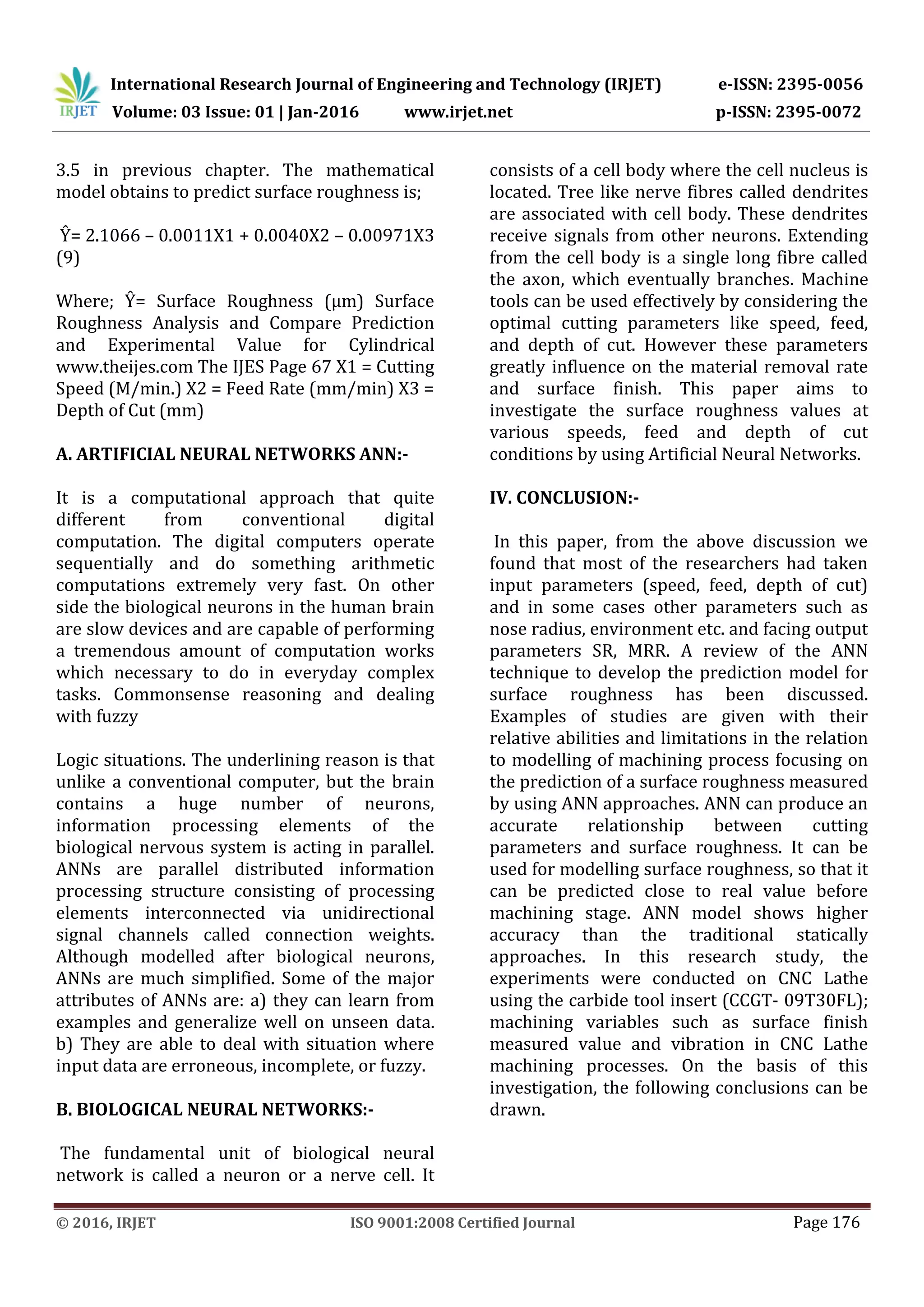
Then, the regression coefficient can be
substituted into the general equation for
multiple regression which shown as equation](https://image.slidesharecdn.com/irjet-v3i130-171014110911/75/Analysis-of-Surface-Roughness-for-Cylindrical-Stainless-Steel-Pipe-Ss-3163-In-CNC-Lathe-Turning-Process-Using-ANN-Method-4-2048.jpg)
![International Research Journal of Engineering and Technology (IRJET) e-ISSN: 2395-0056
Volume: 03 Issue: 01 | Jan-2016 www.irjet.net p-ISSN: 2395-0072
© 2016, IRJET ISO 9001:2008 Certified Journal Page 177
REFERENCES
[1] Benardos, P.G. and Vosniakos,
G.C.,”Prediction of surface roughness in CNC
face milling using neural networks and
Taguchi’s design of experiments.” Robotics and
computer integrated manufacturing, Vol. 18,
pp.343-354, 2002.
[2] Zhang, Julie Z., Chen, Joseph C. and Kirby, E.
Daniel,” Surface roughness optimization in an
end-milling operation using the Taguchi design
method.”Journal of Materials Processing
Technology Vol.184, pp. 233–239, 2007.
[3] Gologlu,Cevdet and Sakarya,Nazim, “The
effects of cutter path strategies on surface
roughness of pocket milling of 1.2738 steel
based on Taguchi method.” Journal of materials
processing technology Vol.206,pp. 7– 15, 2008.
[4] Prajapati, Navneet K. and Patel, S. M.,”
Optimization of process parameters for surface
roughness and material removal rate for SS
316 on CNC turning machine.” International
Journal of Research in Modern Engineering and
Emerging Technology, Vol. 1, Issue: 3, pp.40-47,
2013
[5] Chandrasekaran, K., Marimuthu,P., Raja, K
and ManimaranA,”Machinability study on AISI
410 with different layered inserts in CNC
turning during dry condition.” International
Journal of Engineering& Material Science, Vol.
20, pp.398-404, 2013.
[6] Reddy, B. Sidda, Kumar, J. Suresh and Reddy
K. Vijaya Kumar,” Optimization of surface
roughness in CNC end milling using response
surface methodology and genetic algorithm.”
International Journal of Engineering, Science
and Technology,Vol. 3, No. 8, pp. 102-109,
2011.
[7] Kromanis, A. and Krizbergs, J.,”3d Surface
roughness prediction technique in endmilling
using regression analysis.”( 6th International
DAAAM Baltic Conference Industrial
Engineering),2008.
[8] Bajic, D., Lele,B. and Zivkovic, D.,”Modeling
of machined surface roughness and
optimization of cutting parameters in face
milling.” Vol.47, pp.331-334, 2008.
[9] Chockalingam, P.and Wee Lee Hong,”
Surface Roughness and Tool Wear Study on
Milling of AISI 304 Stainless Steel Using
Different Cooling Conditions.” International
Journal of Engineering and Technology Vol. 2,
No. 8,pp.1386-1392, 2012.
[10] Routara, B. C., Bandyopadhyay,
A.andSahoo, P.,” Roughness modeling
andoptimization in CNC end milling using
response surface method: effect of work piece
material variation.” International Journal of
Advance Manufaturing and Technology,Vol. 40,
pp.1166–1180, 2009.
[11] Thakkar, Jitendra and Patel Mitesh I.,” A
Review on Optimization of Process Parameters
for Surface Roughness and Material Removal
Rate for SS 410 Material during Turning
Operation.”International Journal of Engineering
Research and Applications,Vol. 4, Issue 2,
pp.235-242, 2014.
[12] Newman, S.T. and Nassehi, A.,”Universal
Manufacturing Platform for CNC
Machining.”Annals of the CIRP, Vol. 56, pp. 459-
463, 2007.
[13] Ghani, J.A., Choudhury, I.A. and Hassan,
H.H.,” Application of Taguchi method in the
optimization of end milling parameters.”
Journal of Materials Processing Technology,
Vol. 145, pp. 84–92, 2004 [17] Ross Philip J,
“Taguchi techniques for quality engineering”
(McGraw-Hill book company, New Delhi),2005.
[14]. ANN is the fast fourier transform (FFT)
function and its graphic display were
integrated in to the software program
developed by Mat lab view, data were
visualized in real time. [15]. the method
presented effectively measure surface finish
and vibration of bearing. The goal of this
research is successfully met.
[16]. ANN has been used to learn the collected.
Neural network configuration was trained. The
results of neural network model showed close
matching between the model output and
directly measured vibration. This method
seems to have prediction potentials for non-
experimental pattern additionally ANN
methodology.](https://image.slidesharecdn.com/irjet-v3i130-171014110911/75/Analysis-of-Surface-Roughness-for-Cylindrical-Stainless-Steel-Pipe-Ss-3163-In-CNC-Lathe-Turning-Process-Using-ANN-Method-6-2048.jpg)
![International Research Journal of Engineering and Technology (IRJET) e-ISSN: 2395-0056
Volume: 03 Issue: 01 | Jan-2016 www.irjet.net p-ISSN: 2395-0072
© 2016, IRJET ISO 9001:2008 Certified Journal Page 178
[17]. Optimization method will reduce the
physical testing cost, lead time of prototype
manufacturing cost and it will reduce the
defects of surface roughness of stainless steel
pipes of the company.](https://image.slidesharecdn.com/irjet-v3i130-171014110911/75/Analysis-of-Surface-Roughness-for-Cylindrical-Stainless-Steel-Pipe-Ss-3163-In-CNC-Lathe-Turning-Process-Using-ANN-Method-7-2048.jpg)

This document discusses using artificial neural networks (ANN) to predict surface roughness in cylindrical stainless steel pipes machined using CNC lathe turning. Surface roughness is an important quality metric that is influenced by machining parameters like cutting speed, feed rate, depth of cut, and tool geometry. The document reviews previous research applying ANN and other methods to model surface roughness. It then describes an experiment using ANN to develop a model relating machining parameters to surface roughness measured from turning 316L stainless steel pipes on a CNC lathe. The results indicate ANN is an effective method for accurately predicting surface roughness based on cutting conditions.