SlideShare a Scribd company logo
1 of 3
Download to read offline
Mr.V.H.Waghmare et al. Int. Journal of Engineering Research and Application www.ijera.com
Vol. 3, Issue 5, Sep-Oct 2013, pp.288-290
www.ijera.com 288 | P a g e
Stress Analysis Of Rocker Arm Of Internal Combustion Engine
Mr.V.H.Waghmare1
, Prof. Y.L. Yenarkar 2
1 Student, IV Semester M.Tech (CAD/CAM) Mechanical Engineering Department, Rajiv Gandhi College of
Engg. Research & Technology, Chandrapur-442 401 (Maharashtra) (India)
2
Associate Professor, Mechanical Engineering Department, Rajiv Gandhi College of Engg. Research &
Technology,Chandrapur-442 401 (Maharashtra) (India)
ABSTRACT
The effect of total force i.e. gas pressure, inertia force and initial spring force acting on the existing rocker arm
is evaluated. It is found that the maximum stress is occurred at the push rod side end. For optimization the
various models of rocker arm are developed, keeping its weight constant. The effect of total force on this
various models are evaluated. The model showing less stress is found suitable as compared to other models.
Geometric models are developed in software Pro-E and for analysis software ANSYS 11 is used.
Keywords: Gas pressure, Inertia force, Initial spring force, Analysis.
I. INTRODUCTION
A rocker arm is a reciprocating lever used in
an internal combustion engine to actuate the inlet and
exhaust valves motion as directed by the cam and
follower. The rocker arm of the exhaust valve is the
most heavily loaded. On the other hand the force
required to operate the inlet valve is comparatively
less. However, it is usual practice to make rocker
arms for inlet and exhaust valves identical. This
result in ease of manufacturing. The main objective
of the rocker arm as a ‘lever’ is to change the
direction of force and not the multiplication of the
effort.
While operating, the internal combustion
engine valve produces the various forces which are
acting on the rocker arm. For absorbing this forces,
the rocker arm model must be properly designed.
There is always possibility of optimizing the
designed rocker model by means of stress analysis, so
that stresses induced in the rocker should be
minimized.
NOTATION
ω Angular Velocity
E Modulus of Elasticity
σ bending stress
Pc Cylinder pressure
Pg Force equivalent to gas pressure
Pa Inertia force
Pi Spring force
II. NUMERICAL RESULTS
The various forces acting on the rocker arm
of exhaust valve are ;-
(i) The gas pressure (Pg) on the valve when it opens.
(ii) The inertia force (Pa) when the valve moves up.
(iii) The initial spring force (Pi) to hold the valve on
its seat against suction or negative pressure inside the
cylinder during the suction stroke.
Calculation for gas pressure, Pg
The gas load Pg is given by,
Pg = area of valve × gas pressure when the exhaust
valve opens
Where,
dv = diameter of valve head (mm)
Pc = cylinder pressure or back pressure when the
exhaust valve opens (MPa)
Cylinder pressure, Pc calculation
Mechanical Efficiency = 80% from engine
specification
H.P. = 215 (maximum horse power
assumed)
I.P. = 268.75 H.P.
I.P. = 200487.5 watt.
Where,
MEP = Mean Effective Pressure
L = stroke = 4.02 inch = 0.12 m (assumed)
A = area = (Db = bore diameter is 0.102m
assumed)
N = 2500 rpm
No. of cylinder = 6
200487.5 = 0.122 × MEP
RESEARCH ARTICLE OPEN ACCESS
Mr.V.H.Waghmare et al. Int. Journal of Engineering Research and Application www.ijera.com
Vol. 3, Issue 5, Sep-Oct 2013, pp.288-290
www.ijera.com 289 | P a g e
Cylinder pressure, Pc = MEP = 1636537.8 N/m2
Cylinder pressure, Pc = 1.64 N/mm2
Gas pressure,
= (valve dia., dv = 36 mm
assumed)
Gas pressure, Pg = 1669.32 N
Calculation for Inertia force, Pa
As the valve moves down, the inertia force acts
opposite to the direction of motion. The upward
inertia force Pa is given by,
Pa = mα
Where, m = mass of valve (kg)
α = acceleration of valve (m/s2
)
m = 0.121 kg ( asumed)
Calculation for acceleration, α
Engine speed is 2500rpm, this gives a cam shaft
rotation of 1250 rpm (in a four stroke engine the cam
turns at half the cam shaft speed ). So the time taken
for one revolution of the cam shaft is 0.048 seconds.
Total crankshaft angle when the valve is open,
58+180+50 = 2880
(assumed)
Total angle of cam action for four stroke engine,
Angle of camshaft = ½ angle of camshaft.
Angle of camshaft = ½ 2880
= 1440
Cam is open and close the valve for 1440
of its
rotation. Hence the complete valve cycle is 2/5 of
camshaft rotation or 0.019 seconds.
The equation describing simple harmonic motion
is,
x = a × cos(
Where, x=displacement
a = amplitude
t = time
= angular velocity in radian per second
= 2 × = 2 × 3.142 (time taken for one cycle)
So the value here is,
= 330.737 rad/sec.
Differentiating the equation for expression for
displacement gives ,
v = - × amplitude × sin( , where v = velocity
Then differentiating again,
a = - 2
× a cos(
The maximum acceleration occurs when the term
cos( has the maximum value of 1, this occurs at
the extreme of the motion.
Cam has the lift of 11 mm. (measured value of the
cam shaft of 5.9 liter Cummins B-series engine)
The amplitude of the motion is 5.5mm = 0.0055m.
So the maximum acceleration is given by,
accelerationmax , = (330.737)2
× (0.0055) = 601.63
m/s2
Inertia force, Pa = m
= 0.121 × 601.23
= 72.596 N
Calculation for initial spring force, Pi
Following is the valve spring data assumed:-
Unloaded valve spring length = 53.6mm
Valve spring length installed condition (valve fully
closed) = 42.5 mm
Axial spring force at the axial deflection of the spring
(53.6 - 42.5 = 11.1 mm) = 22.6 kg
= 22.6 × 9.8
= 221.48 N
So initial spring force Pi = 221.48 N
Total Force on the Rocker Arm :-
Total force (Pe) on the rocker arm of the exhaust
valve is given by,
Pe = Pg +Pa + Pi
= 1669.32 + 72.796 + 221.48
Pe = 1963.593 N
By taking the moment the force on the push
rod end is calculated i.e. of 3057.45N
Above calculated force of 1963.593N is applied to
the valve end and the force of 3057.456N is applied
to pushrod end. From the ANSYS result obtained it is
found that expected maximum stresses near the
bearing bore as shown in fig.1 where the moments
are highest. Though the moments on either side of the
boring bore are same, the bending stresses on the
push rod side are higher because of the curvatures
and stress concentration. The deflections and stresses
are in close agreement with the theoretical
calculation.
Since the bending stresses and equivalent
stresses obtained by ANSYS are much lesser than the
permissible stress values. There is a scope for certain
optimization in shape which would equally
distributed stresses as against the current results
which show stress concentration in a particular zone.
Hence it was decided to optimize the shape without
altering the mass. Following section described the
alternate model of rocker arm.
2.1 ALTERATION OF ROCKER ARM
For decreasing the stresses, the model of
rocker arm is modified. The sharp edges of outer
circle is removed by increasing the radius of edge.
Also the material in the outer side of the push rod
circle is increased. While doing this emphasis been
given to the fact that the weight of the rocker arm
should not been increased.
Changes in the existing model is given
below:
Models-I: In this model the edge of the rib is
changed from radius of 0.2mm to 0.4mm.to remove
the sharp contour
Modal-II: In this model the outer radius of push rod
end outer circle is taken as 0.5mm. while the radius
of the outer surface with the rib is taken as 4.5 mm.
Model-III: In this model the outer edge of push rod
end outer surface is taken as 1mm. while the outer
surface radius with the rib is taken to be 4.5 mm.
Model-IV : In this model the outer edge radius of
push rod end outer circle is taken as 1.5 mm. while
the radius of outer surface to the rib is taken to be 5
mm. All the alternate models were further analyzed.
Mr.V.H.Waghmare et al. Int. Journal of Engineering Research and Application www.ijera.com
Vol. 3, Issue 5, Sep-Oct 2013, pp.288-290
www.ijera.com 290 | P a g e
The result obtained are discussed in following
chapter.
III. RESULTS IN ANSYS
“Fig. 1” shows the stress distribution of rocker arm in
which the maximum stress of 560Mpa is observed
near the push rod end.
Fig. 1: The equivalent stress distribution of rocker.
“Fig. 2” shows the ANSYS result of Model-I, in
which the maximum equivalent stress of existing
rocker arm value is reduced to 380Mpa.
Fig. 2: Model-I stress result.
Model-II result shows that there is further reduction
in maximum equivalent stress of Model-I value of
380MPa to 325Mpa. The stress analysis result of
Model-II is shown in the “Fig. 3”
Fig. 3: Model-II stress result
The “Fig. 4” result shows the maximum equivalent
stress of Model-III which is lesser than the maximum
equivalent stress value of Model-II.
Fig. 4: Model-III stress result.
The result of Model-IV shows the maximum
equivalent stress obtained is of 302MPa which is less
than the maximum equivalent stress of Model-III.
The model-IV result is shown in “Fig. 5”.
Fig. 5: Model-IV stress result.
IV. CONCLUSION
The particular section near the top face of
bearing bore towards push rod side in the current
rocker arm shows high stress concentration zone. In
respect of current design of rocker arm it may be
concluded that the stresses in the rocker arm are not
uniformly distributed and there is a scope for
modifying the contour on the said face so as to
reduce the stress concentration.
The curvature in the original design push
rod hole with the main body of rocker arm is too
sharp its radius was varied from 0.5mm to 1.5mm for
a four different values at the same time the region
beneath this curve is filled with material to strengthen
the region. This resulted in strengthening as analysis
showed significant decrease in equivalent stresses in
subsequent alternate models. The best result were
obtained for Model-IV having the maximum stress of
302MPa and the wt. of body is 5.3262×10- 002
kg is
find suitable as compared to previous three models.
Further it may also be concluded that though
the current rocker arm is in having the maximum
equivalent stress much less than the ultimate values
and the rocker arm is serving satisfactorily, there is
scope for modification in respect of shape The
modification proposed are a few and there could be
number of ways, the variation could be made.
However it does not mean that there is an immediate
need to have any alternate design.
REFERENCES
[1] Kun cheng, College of Manufcturing
Science and Engineering,Southwest
University of Science and Technology,
Mianyang China “Finite Element Analysis
for Rocker Arms of verticall Roller Mill on
the ANSYS Workbench”.
[2] Chin-Sung Chung, Ho-Kyung Kin,,
Department of Automobile Engineering,
Seoul national University of Technology,
republic of Korea, “Safety Evaluation of the
Rocker Arm of a diesel engine”.
[3] Z.W. Yu, X. L. Xu , Institute of Metal and
Technology, Dalian Maritime university,
chin, “Failure Analysis of Diesel Engine
Rocker Arm”.
[4] J.W. David and Yimin Wei, North Carolina
State University and J.A. Covey, General
Motors, “Optimal Rocker Arm Design in
High Speed Internal Combustion Engine”.
[5] N. B. Bhandari, Design of Machine Element
(Tata McGraw-Hill).

More Related Content

What's hot

Design, fabrication and performance evaluation of melon shelling machine
Design, fabrication and performance evaluation of melon shelling machineDesign, fabrication and performance evaluation of melon shelling machine
Design, fabrication and performance evaluation of melon shelling machineeSAT Journals
 
3 gear trains(2)
3 gear trains(2)3 gear trains(2)
3 gear trains(2)A-S111
 
COMPARATIVE ANALYSIS OF CRANKSHAFT IN SINGLE CYLINDER PETROL ENGINE CRANKSHAF...
COMPARATIVE ANALYSIS OF CRANKSHAFT IN SINGLE CYLINDER PETROL ENGINE CRANKSHAF...COMPARATIVE ANALYSIS OF CRANKSHAFT IN SINGLE CYLINDER PETROL ENGINE CRANKSHAF...
COMPARATIVE ANALYSIS OF CRANKSHAFT IN SINGLE CYLINDER PETROL ENGINE CRANKSHAF...ijiert bestjournal
 
Design of-gear-box
Design of-gear-boxDesign of-gear-box
Design of-gear-boxmkpq pasha
 
Types of Dynamometers
Types of DynamometersTypes of Dynamometers
Types of DynamometersHarsh Pathak
 
IRJET- Theoretical Analysis of Rocker Arm
IRJET- Theoretical Analysis of Rocker ArmIRJET- Theoretical Analysis of Rocker Arm
IRJET- Theoretical Analysis of Rocker ArmIRJET Journal
 
presentation on dynamometers
presentation on dynamometerspresentation on dynamometers
presentation on dynamometersRakshit vadi
 
DESIGN IMPROVISATION OF ELECTROMECHANICAL ACTUATORS FOR OPERATION AT SUB ZERO...
DESIGN IMPROVISATION OF ELECTROMECHANICAL ACTUATORS FOR OPERATION AT SUB ZERO...DESIGN IMPROVISATION OF ELECTROMECHANICAL ACTUATORS FOR OPERATION AT SUB ZERO...
DESIGN IMPROVISATION OF ELECTROMECHANICAL ACTUATORS FOR OPERATION AT SUB ZERO...ijmech
 
Brakes and dynamometer knw
Brakes and dynamometer knwBrakes and dynamometer knw
Brakes and dynamometer knwKiran Wakchaure
 
Basic of Brakes,
Basic of Brakes, Basic of Brakes,
Basic of Brakes, dodi mulya
 
Unit 1 Introduction and Force Analysis
Unit 1 Introduction and Force AnalysisUnit 1 Introduction and Force Analysis
Unit 1 Introduction and Force AnalysisParrthipan B K
 
FEM analysis_Portfolio_KrishnaPrasad
FEM analysis_Portfolio_KrishnaPrasadFEM analysis_Portfolio_KrishnaPrasad
FEM analysis_Portfolio_KrishnaPrasadkrishnaprasadvn
 
FEM_Modeling_Project_Evaluation of a Steel Pulley and Shaft Design
FEM_Modeling_Project_Evaluation of a Steel Pulley and Shaft DesignFEM_Modeling_Project_Evaluation of a Steel Pulley and Shaft Design
FEM_Modeling_Project_Evaluation of a Steel Pulley and Shaft DesignMehmet Bariskan
 
DESIGN AND ANALYSIS OF STEAM TURBINE ROTOR
  DESIGN AND ANALYSIS OF STEAM TURBINE ROTOR  DESIGN AND ANALYSIS OF STEAM TURBINE ROTOR
DESIGN AND ANALYSIS OF STEAM TURBINE ROTORIAEME Publication
 
Hydraulic Scissor Lift PPT
Hydraulic Scissor Lift PPTHydraulic Scissor Lift PPT
Hydraulic Scissor Lift PPTMechXplain
 
Theory of machine ii 012110050121-1
Theory of machine   ii 012110050121-1Theory of machine   ii 012110050121-1
Theory of machine ii 012110050121-1pyadav13
 
Springs - DESIGN OF MACHINE ELEMENTS-II
Springs - DESIGN OF MACHINE ELEMENTS-IISprings - DESIGN OF MACHINE ELEMENTS-II
Springs - DESIGN OF MACHINE ELEMENTS-IIDr. L K Bhagi
 

What's hot (20)

Design, fabrication and performance evaluation of melon shelling machine
Design, fabrication and performance evaluation of melon shelling machineDesign, fabrication and performance evaluation of melon shelling machine
Design, fabrication and performance evaluation of melon shelling machine
 
Dynamics questions
Dynamics questionsDynamics questions
Dynamics questions
 
3 gear trains(2)
3 gear trains(2)3 gear trains(2)
3 gear trains(2)
 
COMPARATIVE ANALYSIS OF CRANKSHAFT IN SINGLE CYLINDER PETROL ENGINE CRANKSHAF...
COMPARATIVE ANALYSIS OF CRANKSHAFT IN SINGLE CYLINDER PETROL ENGINE CRANKSHAF...COMPARATIVE ANALYSIS OF CRANKSHAFT IN SINGLE CYLINDER PETROL ENGINE CRANKSHAF...
COMPARATIVE ANALYSIS OF CRANKSHAFT IN SINGLE CYLINDER PETROL ENGINE CRANKSHAF...
 
Design of-gear-box
Design of-gear-boxDesign of-gear-box
Design of-gear-box
 
Types of Dynamometers
Types of DynamometersTypes of Dynamometers
Types of Dynamometers
 
IRJET- Theoretical Analysis of Rocker Arm
IRJET- Theoretical Analysis of Rocker ArmIRJET- Theoretical Analysis of Rocker Arm
IRJET- Theoretical Analysis of Rocker Arm
 
Igno
IgnoIgno
Igno
 
presentation on dynamometers
presentation on dynamometerspresentation on dynamometers
presentation on dynamometers
 
DESIGN IMPROVISATION OF ELECTROMECHANICAL ACTUATORS FOR OPERATION AT SUB ZERO...
DESIGN IMPROVISATION OF ELECTROMECHANICAL ACTUATORS FOR OPERATION AT SUB ZERO...DESIGN IMPROVISATION OF ELECTROMECHANICAL ACTUATORS FOR OPERATION AT SUB ZERO...
DESIGN IMPROVISATION OF ELECTROMECHANICAL ACTUATORS FOR OPERATION AT SUB ZERO...
 
Brakes and dynamometer knw
Brakes and dynamometer knwBrakes and dynamometer knw
Brakes and dynamometer knw
 
Basic of Brakes,
Basic of Brakes, Basic of Brakes,
Basic of Brakes,
 
Unit 1 Introduction and Force Analysis
Unit 1 Introduction and Force AnalysisUnit 1 Introduction and Force Analysis
Unit 1 Introduction and Force Analysis
 
FEM analysis_Portfolio_KrishnaPrasad
FEM analysis_Portfolio_KrishnaPrasadFEM analysis_Portfolio_KrishnaPrasad
FEM analysis_Portfolio_KrishnaPrasad
 
FEM_Modeling_Project_Evaluation of a Steel Pulley and Shaft Design
FEM_Modeling_Project_Evaluation of a Steel Pulley and Shaft DesignFEM_Modeling_Project_Evaluation of a Steel Pulley and Shaft Design
FEM_Modeling_Project_Evaluation of a Steel Pulley and Shaft Design
 
DESIGN AND ANALYSIS OF STEAM TURBINE ROTOR
  DESIGN AND ANALYSIS OF STEAM TURBINE ROTOR  DESIGN AND ANALYSIS OF STEAM TURBINE ROTOR
DESIGN AND ANALYSIS OF STEAM TURBINE ROTOR
 
Turning moment-diagram-flywheel
Turning moment-diagram-flywheelTurning moment-diagram-flywheel
Turning moment-diagram-flywheel
 
Hydraulic Scissor Lift PPT
Hydraulic Scissor Lift PPTHydraulic Scissor Lift PPT
Hydraulic Scissor Lift PPT
 
Theory of machine ii 012110050121-1
Theory of machine   ii 012110050121-1Theory of machine   ii 012110050121-1
Theory of machine ii 012110050121-1
 
Springs - DESIGN OF MACHINE ELEMENTS-II
Springs - DESIGN OF MACHINE ELEMENTS-IISprings - DESIGN OF MACHINE ELEMENTS-II
Springs - DESIGN OF MACHINE ELEMENTS-II
 

Viewers also liked (20)

Bc35306309
Bc35306309Bc35306309
Bc35306309
 
Cq35516523
Cq35516523Cq35516523
Cq35516523
 
Cu35540546
Cu35540546Cu35540546
Cu35540546
 
Am35221224
Am35221224Am35221224
Am35221224
 
Ax35277281
Ax35277281Ax35277281
Ax35277281
 
Ar35247251
Ar35247251Ar35247251
Ar35247251
 
Ap35235240
Ap35235240Ap35235240
Ap35235240
 
As35252256
As35252256As35252256
As35252256
 
Ak35206217
Ak35206217Ak35206217
Ak35206217
 
Aq35241246
Aq35241246Aq35241246
Aq35241246
 
At35257260
At35257260At35257260
At35257260
 
Ba35291294
Ba35291294Ba35291294
Ba35291294
 
Bb35295305
Bb35295305Bb35295305
Bb35295305
 
Ao35229234
Ao35229234Ao35229234
Ao35229234
 
Aw35271276
Aw35271276Aw35271276
Aw35271276
 
Al35218220
Al35218220Al35218220
Al35218220
 
An35225228
An35225228An35225228
An35225228
 
Dm32711716
Dm32711716Dm32711716
Dm32711716
 
El33827831
El33827831El33827831
El33827831
 
Eg33794797
Eg33794797Eg33794797
Eg33794797
 

Similar to Az35288290

Design Optimization and Analysis of a Steam Turbine Rotor Grooves
Design Optimization and Analysis of a Steam Turbine Rotor GroovesDesign Optimization and Analysis of a Steam Turbine Rotor Grooves
Design Optimization and Analysis of a Steam Turbine Rotor GroovesIOSR Journals
 
Final Project_ Design and FEM Analysis of Scissor Jack
Final Project_ Design and FEM Analysis of Scissor JackFinal Project_ Design and FEM Analysis of Scissor Jack
Final Project_ Design and FEM Analysis of Scissor JackMehmet Bariskan
 
Final Robot Report
Final Robot ReportFinal Robot Report
Final Robot ReportYuji Heid
 
Finite Element Analysis of Shaft of Centrifugal Pump
Finite Element Analysis of Shaft of Centrifugal PumpFinite Element Analysis of Shaft of Centrifugal Pump
Finite Element Analysis of Shaft of Centrifugal PumpIOSR Journals
 
Experimental investigation of damping force of twin tube shock absorber
Experimental investigation of damping force of twin tube shock absorberExperimental investigation of damping force of twin tube shock absorber
Experimental investigation of damping force of twin tube shock absorberIJERA Editor
 
Finite Element Analysys of Axial Flow Turbine Blade
Finite Element Analysys of Axial Flow Turbine BladeFinite Element Analysys of Axial Flow Turbine Blade
Finite Element Analysys of Axial Flow Turbine BladeIJMER
 
Design, Analysis and Optimization of a 6 cylinder Engine Crank shaft
Design, Analysis and Optimization of a 6 cylinder Engine Crank  shaftDesign, Analysis and Optimization of a 6 cylinder Engine Crank  shaft
Design, Analysis and Optimization of a 6 cylinder Engine Crank shaftIJMER
 
Generation of Air Swirl through Inlet Poppet Valve Modification and To Enhanc...
Generation of Air Swirl through Inlet Poppet Valve Modification and To Enhanc...Generation of Air Swirl through Inlet Poppet Valve Modification and To Enhanc...
Generation of Air Swirl through Inlet Poppet Valve Modification and To Enhanc...iosrjce
 
Review of shaft failure in Coil Car Assembly
Review of shaft failure in Coil Car AssemblyReview of shaft failure in Coil Car Assembly
Review of shaft failure in Coil Car AssemblyIRJET Journal
 
IRJET- Design, Testing and Analysis of Spherical and Aerodynamic Helmet in Op...
IRJET- Design, Testing and Analysis of Spherical and Aerodynamic Helmet in Op...IRJET- Design, Testing and Analysis of Spherical and Aerodynamic Helmet in Op...
IRJET- Design, Testing and Analysis of Spherical and Aerodynamic Helmet in Op...IRJET Journal
 
Optimum design of braking system for a formula 3 race cars with numeric compu...
Optimum design of braking system for a formula 3 race cars with numeric compu...Optimum design of braking system for a formula 3 race cars with numeric compu...
Optimum design of braking system for a formula 3 race cars with numeric compu...IRJET Journal
 
Finite Element Analysis of Obround Pressure Vessels
Finite Element Analysis of Obround Pressure VesselsFinite Element Analysis of Obround Pressure Vessels
Finite Element Analysis of Obround Pressure VesselsIJMER
 
IRJET- To Design a New Cross Section for Connecting Rod with a Target of ...
IRJET-  	  To Design a New Cross Section for Connecting Rod with a Target of ...IRJET-  	  To Design a New Cross Section for Connecting Rod with a Target of ...
IRJET- To Design a New Cross Section for Connecting Rod with a Target of ...IRJET Journal
 
4. static and_dynamic_analysis.full
4. static and_dynamic_analysis.full4. static and_dynamic_analysis.full
4. static and_dynamic_analysis.fullVivek Fegade
 
GEOMETRIC OPTIMIZATION OF CRANK SHAFT FOR OPTIMUM DESIGN AND IMPROVEMENT OF LIFE
GEOMETRIC OPTIMIZATION OF CRANK SHAFT FOR OPTIMUM DESIGN AND IMPROVEMENT OF LIFEGEOMETRIC OPTIMIZATION OF CRANK SHAFT FOR OPTIMUM DESIGN AND IMPROVEMENT OF LIFE
GEOMETRIC OPTIMIZATION OF CRANK SHAFT FOR OPTIMUM DESIGN AND IMPROVEMENT OF LIFEIjripublishers Ijri
 
DESIGN, OPTIMIZATION AND FINITE ELEMENT ANALYSIS OF CRANKSHAFT
DESIGN, OPTIMIZATION AND FINITE ELEMENT ANALYSIS OF CRANKSHAFTDESIGN, OPTIMIZATION AND FINITE ELEMENT ANALYSIS OF CRANKSHAFT
DESIGN, OPTIMIZATION AND FINITE ELEMENT ANALYSIS OF CRANKSHAFTijiert bestjournal
 

Similar to Az35288290 (20)

Design Optimization and Analysis of a Steam Turbine Rotor Grooves
Design Optimization and Analysis of a Steam Turbine Rotor GroovesDesign Optimization and Analysis of a Steam Turbine Rotor Grooves
Design Optimization and Analysis of a Steam Turbine Rotor Grooves
 
Final Project_ Design and FEM Analysis of Scissor Jack
Final Project_ Design and FEM Analysis of Scissor JackFinal Project_ Design and FEM Analysis of Scissor Jack
Final Project_ Design and FEM Analysis of Scissor Jack
 
Ijmet 06 10_013
Ijmet 06 10_013Ijmet 06 10_013
Ijmet 06 10_013
 
Final Robot Report
Final Robot ReportFinal Robot Report
Final Robot Report
 
Finite Element Analysis of Shaft of Centrifugal Pump
Finite Element Analysis of Shaft of Centrifugal PumpFinite Element Analysis of Shaft of Centrifugal Pump
Finite Element Analysis of Shaft of Centrifugal Pump
 
Experimental investigation of damping force of twin tube shock absorber
Experimental investigation of damping force of twin tube shock absorberExperimental investigation of damping force of twin tube shock absorber
Experimental investigation of damping force of twin tube shock absorber
 
Finite Element Analysys of Axial Flow Turbine Blade
Finite Element Analysys of Axial Flow Turbine BladeFinite Element Analysys of Axial Flow Turbine Blade
Finite Element Analysys of Axial Flow Turbine Blade
 
Design, Analysis and Optimization of a 6 cylinder Engine Crank shaft
Design, Analysis and Optimization of a 6 cylinder Engine Crank  shaftDesign, Analysis and Optimization of a 6 cylinder Engine Crank  shaft
Design, Analysis and Optimization of a 6 cylinder Engine Crank shaft
 
J012665565
J012665565J012665565
J012665565
 
Generation of Air Swirl through Inlet Poppet Valve Modification and To Enhanc...
Generation of Air Swirl through Inlet Poppet Valve Modification and To Enhanc...Generation of Air Swirl through Inlet Poppet Valve Modification and To Enhanc...
Generation of Air Swirl through Inlet Poppet Valve Modification and To Enhanc...
 
Review of shaft failure in Coil Car Assembly
Review of shaft failure in Coil Car AssemblyReview of shaft failure in Coil Car Assembly
Review of shaft failure in Coil Car Assembly
 
pro/e
pro/epro/e
pro/e
 
IRJET- Design, Testing and Analysis of Spherical and Aerodynamic Helmet in Op...
IRJET- Design, Testing and Analysis of Spherical and Aerodynamic Helmet in Op...IRJET- Design, Testing and Analysis of Spherical and Aerodynamic Helmet in Op...
IRJET- Design, Testing and Analysis of Spherical and Aerodynamic Helmet in Op...
 
Optimum design of braking system for a formula 3 race cars with numeric compu...
Optimum design of braking system for a formula 3 race cars with numeric compu...Optimum design of braking system for a formula 3 race cars with numeric compu...
Optimum design of braking system for a formula 3 race cars with numeric compu...
 
Finite Element Analysis of Obround Pressure Vessels
Finite Element Analysis of Obround Pressure VesselsFinite Element Analysis of Obround Pressure Vessels
Finite Element Analysis of Obround Pressure Vessels
 
IRJET- To Design a New Cross Section for Connecting Rod with a Target of ...
IRJET-  	  To Design a New Cross Section for Connecting Rod with a Target of ...IRJET-  	  To Design a New Cross Section for Connecting Rod with a Target of ...
IRJET- To Design a New Cross Section for Connecting Rod with a Target of ...
 
4. static and_dynamic_analysis.full
4. static and_dynamic_analysis.full4. static and_dynamic_analysis.full
4. static and_dynamic_analysis.full
 
P410394102
P410394102P410394102
P410394102
 
GEOMETRIC OPTIMIZATION OF CRANK SHAFT FOR OPTIMUM DESIGN AND IMPROVEMENT OF LIFE
GEOMETRIC OPTIMIZATION OF CRANK SHAFT FOR OPTIMUM DESIGN AND IMPROVEMENT OF LIFEGEOMETRIC OPTIMIZATION OF CRANK SHAFT FOR OPTIMUM DESIGN AND IMPROVEMENT OF LIFE
GEOMETRIC OPTIMIZATION OF CRANK SHAFT FOR OPTIMUM DESIGN AND IMPROVEMENT OF LIFE
 
DESIGN, OPTIMIZATION AND FINITE ELEMENT ANALYSIS OF CRANKSHAFT
DESIGN, OPTIMIZATION AND FINITE ELEMENT ANALYSIS OF CRANKSHAFTDESIGN, OPTIMIZATION AND FINITE ELEMENT ANALYSIS OF CRANKSHAFT
DESIGN, OPTIMIZATION AND FINITE ELEMENT ANALYSIS OF CRANKSHAFT
 

Recently uploaded

"Federated learning: out of reach no matter how close",Oleksandr Lapshyn
"Federated learning: out of reach no matter how close",Oleksandr Lapshyn"Federated learning: out of reach no matter how close",Oleksandr Lapshyn
"Federated learning: out of reach no matter how close",Oleksandr LapshynFwdays
 
Unleash Your Potential - Namagunga Girls Coding Club
Unleash Your Potential - Namagunga Girls Coding ClubUnleash Your Potential - Namagunga Girls Coding Club
Unleash Your Potential - Namagunga Girls Coding ClubKalema Edgar
 
Install Stable Diffusion in windows machine
Install Stable Diffusion in windows machineInstall Stable Diffusion in windows machine
Install Stable Diffusion in windows machinePadma Pradeep
 
AI as an Interface for Commercial Buildings
AI as an Interface for Commercial BuildingsAI as an Interface for Commercial Buildings
AI as an Interface for Commercial BuildingsMemoori
 
Designing IA for AI - Information Architecture Conference 2024
Designing IA for AI - Information Architecture Conference 2024Designing IA for AI - Information Architecture Conference 2024
Designing IA for AI - Information Architecture Conference 2024Enterprise Knowledge
 
Presentation on how to chat with PDF using ChatGPT code interpreter
Presentation on how to chat with PDF using ChatGPT code interpreterPresentation on how to chat with PDF using ChatGPT code interpreter
Presentation on how to chat with PDF using ChatGPT code interpreternaman860154
 
Automating Business Process via MuleSoft Composer | Bangalore MuleSoft Meetup...
Automating Business Process via MuleSoft Composer | Bangalore MuleSoft Meetup...Automating Business Process via MuleSoft Composer | Bangalore MuleSoft Meetup...
Automating Business Process via MuleSoft Composer | Bangalore MuleSoft Meetup...shyamraj55
 
Tech-Forward - Achieving Business Readiness For Copilot in Microsoft 365
Tech-Forward - Achieving Business Readiness For Copilot in Microsoft 365Tech-Forward - Achieving Business Readiness For Copilot in Microsoft 365
Tech-Forward - Achieving Business Readiness For Copilot in Microsoft 3652toLead Limited
 
APIForce Zurich 5 April Automation LPDG
APIForce Zurich 5 April  Automation LPDGAPIForce Zurich 5 April  Automation LPDG
APIForce Zurich 5 April Automation LPDGMarianaLemus7
 
Pigging Solutions in Pet Food Manufacturing
Pigging Solutions in Pet Food ManufacturingPigging Solutions in Pet Food Manufacturing
Pigging Solutions in Pet Food ManufacturingPigging Solutions
 
Enhancing Worker Digital Experience: A Hands-on Workshop for Partners
Enhancing Worker Digital Experience: A Hands-on Workshop for PartnersEnhancing Worker Digital Experience: A Hands-on Workshop for Partners
Enhancing Worker Digital Experience: A Hands-on Workshop for PartnersThousandEyes
 
Streamlining Python Development: A Guide to a Modern Project Setup
Streamlining Python Development: A Guide to a Modern Project SetupStreamlining Python Development: A Guide to a Modern Project Setup
Streamlining Python Development: A Guide to a Modern Project SetupFlorian Wilhelm
 
CloudStudio User manual (basic edition):
CloudStudio User manual (basic edition):CloudStudio User manual (basic edition):
CloudStudio User manual (basic edition):comworks
 
Human Factors of XR: Using Human Factors to Design XR Systems
Human Factors of XR: Using Human Factors to Design XR SystemsHuman Factors of XR: Using Human Factors to Design XR Systems
Human Factors of XR: Using Human Factors to Design XR SystemsMark Billinghurst
 
Breaking the Kubernetes Kill Chain: Host Path Mount
Breaking the Kubernetes Kill Chain: Host Path MountBreaking the Kubernetes Kill Chain: Host Path Mount
Breaking the Kubernetes Kill Chain: Host Path MountPuma Security, LLC
 
FULL ENJOY 🔝 8264348440 🔝 Call Girls in Diplomatic Enclave | Delhi
FULL ENJOY 🔝 8264348440 🔝 Call Girls in Diplomatic Enclave | DelhiFULL ENJOY 🔝 8264348440 🔝 Call Girls in Diplomatic Enclave | Delhi
FULL ENJOY 🔝 8264348440 🔝 Call Girls in Diplomatic Enclave | Delhisoniya singh
 
Artificial intelligence in the post-deep learning era
Artificial intelligence in the post-deep learning eraArtificial intelligence in the post-deep learning era
Artificial intelligence in the post-deep learning eraDeakin University
 
My Hashitalk Indonesia April 2024 Presentation
My Hashitalk Indonesia April 2024 PresentationMy Hashitalk Indonesia April 2024 Presentation
My Hashitalk Indonesia April 2024 PresentationRidwan Fadjar
 
Understanding the Laravel MVC Architecture
Understanding the Laravel MVC ArchitectureUnderstanding the Laravel MVC Architecture
Understanding the Laravel MVC ArchitecturePixlogix Infotech
 

Recently uploaded (20)

"Federated learning: out of reach no matter how close",Oleksandr Lapshyn
"Federated learning: out of reach no matter how close",Oleksandr Lapshyn"Federated learning: out of reach no matter how close",Oleksandr Lapshyn
"Federated learning: out of reach no matter how close",Oleksandr Lapshyn
 
Unleash Your Potential - Namagunga Girls Coding Club
Unleash Your Potential - Namagunga Girls Coding ClubUnleash Your Potential - Namagunga Girls Coding Club
Unleash Your Potential - Namagunga Girls Coding Club
 
Install Stable Diffusion in windows machine
Install Stable Diffusion in windows machineInstall Stable Diffusion in windows machine
Install Stable Diffusion in windows machine
 
AI as an Interface for Commercial Buildings
AI as an Interface for Commercial BuildingsAI as an Interface for Commercial Buildings
AI as an Interface for Commercial Buildings
 
Designing IA for AI - Information Architecture Conference 2024
Designing IA for AI - Information Architecture Conference 2024Designing IA for AI - Information Architecture Conference 2024
Designing IA for AI - Information Architecture Conference 2024
 
Presentation on how to chat with PDF using ChatGPT code interpreter
Presentation on how to chat with PDF using ChatGPT code interpreterPresentation on how to chat with PDF using ChatGPT code interpreter
Presentation on how to chat with PDF using ChatGPT code interpreter
 
Automating Business Process via MuleSoft Composer | Bangalore MuleSoft Meetup...
Automating Business Process via MuleSoft Composer | Bangalore MuleSoft Meetup...Automating Business Process via MuleSoft Composer | Bangalore MuleSoft Meetup...
Automating Business Process via MuleSoft Composer | Bangalore MuleSoft Meetup...
 
Tech-Forward - Achieving Business Readiness For Copilot in Microsoft 365
Tech-Forward - Achieving Business Readiness For Copilot in Microsoft 365Tech-Forward - Achieving Business Readiness For Copilot in Microsoft 365
Tech-Forward - Achieving Business Readiness For Copilot in Microsoft 365
 
APIForce Zurich 5 April Automation LPDG
APIForce Zurich 5 April  Automation LPDGAPIForce Zurich 5 April  Automation LPDG
APIForce Zurich 5 April Automation LPDG
 
Pigging Solutions in Pet Food Manufacturing
Pigging Solutions in Pet Food ManufacturingPigging Solutions in Pet Food Manufacturing
Pigging Solutions in Pet Food Manufacturing
 
Enhancing Worker Digital Experience: A Hands-on Workshop for Partners
Enhancing Worker Digital Experience: A Hands-on Workshop for PartnersEnhancing Worker Digital Experience: A Hands-on Workshop for Partners
Enhancing Worker Digital Experience: A Hands-on Workshop for Partners
 
Streamlining Python Development: A Guide to a Modern Project Setup
Streamlining Python Development: A Guide to a Modern Project SetupStreamlining Python Development: A Guide to a Modern Project Setup
Streamlining Python Development: A Guide to a Modern Project Setup
 
CloudStudio User manual (basic edition):
CloudStudio User manual (basic edition):CloudStudio User manual (basic edition):
CloudStudio User manual (basic edition):
 
Human Factors of XR: Using Human Factors to Design XR Systems
Human Factors of XR: Using Human Factors to Design XR SystemsHuman Factors of XR: Using Human Factors to Design XR Systems
Human Factors of XR: Using Human Factors to Design XR Systems
 
Breaking the Kubernetes Kill Chain: Host Path Mount
Breaking the Kubernetes Kill Chain: Host Path MountBreaking the Kubernetes Kill Chain: Host Path Mount
Breaking the Kubernetes Kill Chain: Host Path Mount
 
Vulnerability_Management_GRC_by Sohang Sengupta.pptx
Vulnerability_Management_GRC_by Sohang Sengupta.pptxVulnerability_Management_GRC_by Sohang Sengupta.pptx
Vulnerability_Management_GRC_by Sohang Sengupta.pptx
 
FULL ENJOY 🔝 8264348440 🔝 Call Girls in Diplomatic Enclave | Delhi
FULL ENJOY 🔝 8264348440 🔝 Call Girls in Diplomatic Enclave | DelhiFULL ENJOY 🔝 8264348440 🔝 Call Girls in Diplomatic Enclave | Delhi
FULL ENJOY 🔝 8264348440 🔝 Call Girls in Diplomatic Enclave | Delhi
 
Artificial intelligence in the post-deep learning era
Artificial intelligence in the post-deep learning eraArtificial intelligence in the post-deep learning era
Artificial intelligence in the post-deep learning era
 
My Hashitalk Indonesia April 2024 Presentation
My Hashitalk Indonesia April 2024 PresentationMy Hashitalk Indonesia April 2024 Presentation
My Hashitalk Indonesia April 2024 Presentation
 
Understanding the Laravel MVC Architecture
Understanding the Laravel MVC ArchitectureUnderstanding the Laravel MVC Architecture
Understanding the Laravel MVC Architecture
 

Az35288290

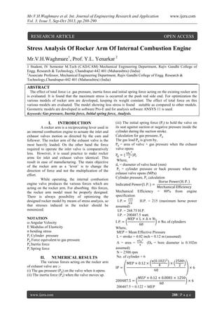
  • 1. Mr.V.H.Waghmare et al. Int. Journal of Engineering Research and Application www.ijera.com Vol. 3, Issue 5, Sep-Oct 2013, pp.288-290 www.ijera.com 288 | P a g e Stress Analysis Of Rocker Arm Of Internal Combustion Engine Mr.V.H.Waghmare1 , Prof. Y.L. Yenarkar 2 1 Student, IV Semester M.Tech (CAD/CAM) Mechanical Engineering Department, Rajiv Gandhi College of Engg. Research & Technology, Chandrapur-442 401 (Maharashtra) (India) 2 Associate Professor, Mechanical Engineering Department, Rajiv Gandhi College of Engg. Research & Technology,Chandrapur-442 401 (Maharashtra) (India) ABSTRACT The effect of total force i.e. gas pressure, inertia force and initial spring force acting on the existing rocker arm is evaluated. It is found that the maximum stress is occurred at the push rod side end. For optimization the various models of rocker arm are developed, keeping its weight constant. The effect of total force on this various models are evaluated. The model showing less stress is found suitable as compared to other models. Geometric models are developed in software Pro-E and for analysis software ANSYS 11 is used. Keywords: Gas pressure, Inertia force, Initial spring force, Analysis. I. INTRODUCTION A rocker arm is a reciprocating lever used in an internal combustion engine to actuate the inlet and exhaust valves motion as directed by the cam and follower. The rocker arm of the exhaust valve is the most heavily loaded. On the other hand the force required to operate the inlet valve is comparatively less. However, it is usual practice to make rocker arms for inlet and exhaust valves identical. This result in ease of manufacturing. The main objective of the rocker arm as a ‘lever’ is to change the direction of force and not the multiplication of the effort. While operating, the internal combustion engine valve produces the various forces which are acting on the rocker arm. For absorbing this forces, the rocker arm model must be properly designed. There is always possibility of optimizing the designed rocker model by means of stress analysis, so that stresses induced in the rocker should be minimized. NOTATION ω Angular Velocity E Modulus of Elasticity σ bending stress Pc Cylinder pressure Pg Force equivalent to gas pressure Pa Inertia force Pi Spring force II. NUMERICAL RESULTS The various forces acting on the rocker arm of exhaust valve are ;- (i) The gas pressure (Pg) on the valve when it opens. (ii) The inertia force (Pa) when the valve moves up. (iii) The initial spring force (Pi) to hold the valve on its seat against suction or negative pressure inside the cylinder during the suction stroke. Calculation for gas pressure, Pg The gas load Pg is given by, Pg = area of valve × gas pressure when the exhaust valve opens Where, dv = diameter of valve head (mm) Pc = cylinder pressure or back pressure when the exhaust valve opens (MPa) Cylinder pressure, Pc calculation Mechanical Efficiency = 80% from engine specification H.P. = 215 (maximum horse power assumed) I.P. = 268.75 H.P. I.P. = 200487.5 watt. Where, MEP = Mean Effective Pressure L = stroke = 4.02 inch = 0.12 m (assumed) A = area = (Db = bore diameter is 0.102m assumed) N = 2500 rpm No. of cylinder = 6 200487.5 = 0.122 × MEP RESEARCH ARTICLE OPEN ACCESS
  • 2. Mr.V.H.Waghmare et al. Int. Journal of Engineering Research and Application www.ijera.com Vol. 3, Issue 5, Sep-Oct 2013, pp.288-290 www.ijera.com 289 | P a g e Cylinder pressure, Pc = MEP = 1636537.8 N/m2 Cylinder pressure, Pc = 1.64 N/mm2 Gas pressure, = (valve dia., dv = 36 mm assumed) Gas pressure, Pg = 1669.32 N Calculation for Inertia force, Pa As the valve moves down, the inertia force acts opposite to the direction of motion. The upward inertia force Pa is given by, Pa = mα Where, m = mass of valve (kg) α = acceleration of valve (m/s2 ) m = 0.121 kg ( asumed) Calculation for acceleration, α Engine speed is 2500rpm, this gives a cam shaft rotation of 1250 rpm (in a four stroke engine the cam turns at half the cam shaft speed ). So the time taken for one revolution of the cam shaft is 0.048 seconds. Total crankshaft angle when the valve is open, 58+180+50 = 2880 (assumed) Total angle of cam action for four stroke engine, Angle of camshaft = ½ angle of camshaft. Angle of camshaft = ½ 2880 = 1440 Cam is open and close the valve for 1440 of its rotation. Hence the complete valve cycle is 2/5 of camshaft rotation or 0.019 seconds. The equation describing simple harmonic motion is, x = a × cos( Where, x=displacement a = amplitude t = time = angular velocity in radian per second = 2 × = 2 × 3.142 (time taken for one cycle) So the value here is, = 330.737 rad/sec. Differentiating the equation for expression for displacement gives , v = - × amplitude × sin( , where v = velocity Then differentiating again, a = - 2 × a cos( The maximum acceleration occurs when the term cos( has the maximum value of 1, this occurs at the extreme of the motion. Cam has the lift of 11 mm. (measured value of the cam shaft of 5.9 liter Cummins B-series engine) The amplitude of the motion is 5.5mm = 0.0055m. So the maximum acceleration is given by, accelerationmax , = (330.737)2 × (0.0055) = 601.63 m/s2 Inertia force, Pa = m = 0.121 × 601.23 = 72.596 N Calculation for initial spring force, Pi Following is the valve spring data assumed:- Unloaded valve spring length = 53.6mm Valve spring length installed condition (valve fully closed) = 42.5 mm Axial spring force at the axial deflection of the spring (53.6 - 42.5 = 11.1 mm) = 22.6 kg = 22.6 × 9.8 = 221.48 N So initial spring force Pi = 221.48 N Total Force on the Rocker Arm :- Total force (Pe) on the rocker arm of the exhaust valve is given by, Pe = Pg +Pa + Pi = 1669.32 + 72.796 + 221.48 Pe = 1963.593 N By taking the moment the force on the push rod end is calculated i.e. of 3057.45N Above calculated force of 1963.593N is applied to the valve end and the force of 3057.456N is applied to pushrod end. From the ANSYS result obtained it is found that expected maximum stresses near the bearing bore as shown in fig.1 where the moments are highest. Though the moments on either side of the boring bore are same, the bending stresses on the push rod side are higher because of the curvatures and stress concentration. The deflections and stresses are in close agreement with the theoretical calculation. Since the bending stresses and equivalent stresses obtained by ANSYS are much lesser than the permissible stress values. There is a scope for certain optimization in shape which would equally distributed stresses as against the current results which show stress concentration in a particular zone. Hence it was decided to optimize the shape without altering the mass. Following section described the alternate model of rocker arm. 2.1 ALTERATION OF ROCKER ARM For decreasing the stresses, the model of rocker arm is modified. The sharp edges of outer circle is removed by increasing the radius of edge. Also the material in the outer side of the push rod circle is increased. While doing this emphasis been given to the fact that the weight of the rocker arm should not been increased. Changes in the existing model is given below: Models-I: In this model the edge of the rib is changed from radius of 0.2mm to 0.4mm.to remove the sharp contour Modal-II: In this model the outer radius of push rod end outer circle is taken as 0.5mm. while the radius of the outer surface with the rib is taken as 4.5 mm. Model-III: In this model the outer edge of push rod end outer surface is taken as 1mm. while the outer surface radius with the rib is taken to be 4.5 mm. Model-IV : In this model the outer edge radius of push rod end outer circle is taken as 1.5 mm. while the radius of outer surface to the rib is taken to be 5 mm. All the alternate models were further analyzed.
  • 3. Mr.V.H.Waghmare et al. Int. Journal of Engineering Research and Application www.ijera.com Vol. 3, Issue 5, Sep-Oct 2013, pp.288-290 www.ijera.com 290 | P a g e The result obtained are discussed in following chapter. III. RESULTS IN ANSYS “Fig. 1” shows the stress distribution of rocker arm in which the maximum stress of 560Mpa is observed near the push rod end. Fig. 1: The equivalent stress distribution of rocker. “Fig. 2” shows the ANSYS result of Model-I, in which the maximum equivalent stress of existing rocker arm value is reduced to 380Mpa. Fig. 2: Model-I stress result. Model-II result shows that there is further reduction in maximum equivalent stress of Model-I value of 380MPa to 325Mpa. The stress analysis result of Model-II is shown in the “Fig. 3” Fig. 3: Model-II stress result The “Fig. 4” result shows the maximum equivalent stress of Model-III which is lesser than the maximum equivalent stress value of Model-II. Fig. 4: Model-III stress result. The result of Model-IV shows the maximum equivalent stress obtained is of 302MPa which is less than the maximum equivalent stress of Model-III. The model-IV result is shown in “Fig. 5”. Fig. 5: Model-IV stress result. IV. CONCLUSION The particular section near the top face of bearing bore towards push rod side in the current rocker arm shows high stress concentration zone. In respect of current design of rocker arm it may be concluded that the stresses in the rocker arm are not uniformly distributed and there is a scope for modifying the contour on the said face so as to reduce the stress concentration. The curvature in the original design push rod hole with the main body of rocker arm is too sharp its radius was varied from 0.5mm to 1.5mm for a four different values at the same time the region beneath this curve is filled with material to strengthen the region. This resulted in strengthening as analysis showed significant decrease in equivalent stresses in subsequent alternate models. The best result were obtained for Model-IV having the maximum stress of 302MPa and the wt. of body is 5.3262×10- 002 kg is find suitable as compared to previous three models. Further it may also be concluded that though the current rocker arm is in having the maximum equivalent stress much less than the ultimate values and the rocker arm is serving satisfactorily, there is scope for modification in respect of shape The modification proposed are a few and there could be number of ways, the variation could be made. However it does not mean that there is an immediate need to have any alternate design. REFERENCES [1] Kun cheng, College of Manufcturing Science and Engineering,Southwest University of Science and Technology, Mianyang China “Finite Element Analysis for Rocker Arms of verticall Roller Mill on the ANSYS Workbench”. [2] Chin-Sung Chung, Ho-Kyung Kin,, Department of Automobile Engineering, Seoul national University of Technology, republic of Korea, “Safety Evaluation of the Rocker Arm of a diesel engine”. [3] Z.W. Yu, X. L. Xu , Institute of Metal and Technology, Dalian Maritime university, chin, “Failure Analysis of Diesel Engine Rocker Arm”. [4] J.W. David and Yimin Wei, North Carolina State University and J.A. Covey, General Motors, “Optimal Rocker Arm Design in High Speed Internal Combustion Engine”. [5] N. B. Bhandari, Design of Machine Element (Tata McGraw-Hill).