

Recommended
More Related Content
What's hot
What's hot (17)
Viewers also liked
Viewers also liked (20)
Similar to J012665565
Similar to J012665565 (20)
More from IOSR Journals
Recently uploaded
Recently uploaded (20)
J012665565
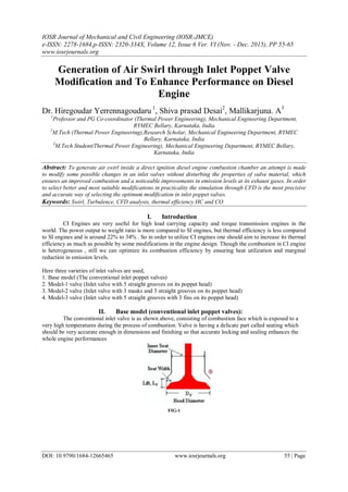
- 1. IOSR Journal of Mechanical and Civil Engineering (IOSR-JMCE) e-ISSN: 2278-1684,p-ISSN: 2320-334X, Volume 12, Issue 6 Ver. VI (Nov. - Dec. 2015), PP 55-65 www.iosrjournals.org DOI: 10.9790/1684-12665465 www.iosrjournals.org 55 | Page Generation of Air Swirl through Inlet Poppet Valve Modification and To Enhance Performance on Diesel Engine Dr. Hiregoudar Yerrennagoudaru 1 , Shiva prasad Desai2 , Mallikarjuna. A3 1 Professor and PG Co-coordinator (Thermal Power Engineering), Mechanical Engineering Department, RYMEC Bellary, Karnataka, India 2 M.Tech (Thermal Power Engineering),Research Scholar, Mechanical Engineering Department, RYMEC Bellary, Karnataka, India 3 M.Tech Student(Thermal Power Engineering), Mechanical Engineering Department, RYMEC Bellary, Karnataka, India Abstract: To generate air swirl inside a direct ignition diesel engine combustion chamber an attempt is made to modify some possible changes in an inlet valves without disturbing the properties of valve material, which ensures an improved combustion and a noticeable improvements in emission levels at its exhaust gases. In order to select better and most suitable modifications in practicality the simulation through CFD is the most precisive and accurate way of selecting the optimum modification in inlet poppet valves. Keywords: Swirl, Turbulence, CFD analysis, thermal efficiency HC and CO I. Introduction CI Engines are very useful for high load carrying capacity and torque transmission engines in the world. The power output to weight ratio is more compared to SI engines, but thermal efficiency is less compared to SI engines and is around 22% to 34% . So in order to utilize CI engines one should aim to increase its thermal efficiency as much as possible by some modifications in the engine design. Though the combustion in CI engine is heterogeneous , still we can optimize its combustion efficiency by ensuring heat utilization and marginal reduction in emission levels. Here three varieties of inlet valves are used, 1. Base model (The conventional inlet poppet valves) 2. Model-1 valve (Inlet valve with 5 straight grooves on its poppet head) 3. Model-2 valve (Inlet valve with 3 masks and 3 straight grooves on its poppet head) 4. Model-3 valve (Inlet valve with 5 straight grooves with 3 fins on its poppet head) II. Base model (conventional inlet poppet valves): The conventional inlet valve is as shown above, consisting of combustion face which is exposed to a very high temperatures during the process of combustion. Valve is having a delicate part called seating which should be very accurate enough in dimensions and finishing so that accurate locking and sealing enhances the whole engine performances FIG-1
- 2. Generation of Inlet Air swirl by modification of Inlet Poppet Valve and To Enhance performance… DOI: 10.9790/1684-12665465 www.iosrjournals.org 56 | Page Model-1 valve (Inlet valve with 5 straight grooves on its poppet head) Width of groove: 3mm Depth of groove: 3mm Outer dia of grooves: 22mm Inner dia of grooves: 8mm Fig-2 Grooving is the process of removing a small piece of metal on the valve head without disturbing the valve seating; the small cavities are called grooves. Here for analysis we have used 2-grooved valves, 3- grooved valve and 5- grooved valve, which are having the following dimensions: Model-2 valve (Inlet valve with 3 masks and 3 straight grooves on its back) Width of groove: 3mm Depth of groove: 3mm Outer dia of grooves: 22mm Inner dia of grooves: 8mm Angle of each mask: 45degrees. Thickness of mask: 4mm Width of mask: 4mm Fig-2 In this type a valve consisting a grooves three in numbers with small pieces build on head as shown in fig-2. This type of design utilizes a combination of small built-up pieces called MASKS and a CAVITIES called grooves. For analysis 2groove-2mask, 3Groove-3masks are simulated through CFD. Model-3 valve (Inlet valve with 5 straight grooves with 3 fins on its poppet head) Width of groove: 3mm Depth of groove: 3mm Outer dia of grooves: 22mm Inner dia of grooves: 8mm Dia of ring: 7.9mm Length of blade: 6.5mm Width: 4mm Fig-3 In this type a small ring with blades are attached to valve as shown in figure-3. It uses a combination of grooves three in numbers and a freely rotatable ring with 3 blades. For CFD analysis the 3Groove-5bladed ring and 5groove-3bladed ring are simulated. Simulation using CFD: Simulation requires valve models, engine inlet manifold model, combustion chamber model, engine operating parameters. Discussion of each may become a very lengthy topics hence just explained through some neat sketches.
- 3. Generation of Inlet Air swirl by modification of Inlet Poppet Valve and To Enhance performance… DOI: 10.9790/1684-12665465 www.iosrjournals.org 57 | Page Engine operating parameters: WATER COOLED, SINGLE CYLINDER, 4-STROKE DIESEL ENGINE SPECIFICATIONS: BHP = 5HP = 3.68KW Bore Diameter = 80mm Stroke length = 110mm Speed = 1500rpm Brake drum Radius = 147mm C.V of Diesel = 45, 355 Kj / Kg Specific Gravity of diesel = 0.8225gms/cc Orifice dia = 15mm Brake Rope dia = 15.9 mm Torque arm radius = 0.2 mts Compression ratio = 16.5:1 Simulation By Using Cfd: Here valve lift is considered as major criterion for simulation. Total valve lift = 12mm This 12mm is divided into 3 parts and called as Low Lift (valve at 4mm downward movement) Medium lift (valve at 8mm downward movement) High lift (valve at12mm downward movement) Hence CFD simulations were carried out for analyzing swirl, turbulence, velocity of inlet air and also pressure distribution inside the cylinder during suction stroke and are analyzed at different inlet valve lift positions in comparison with base model. III. ANALYSIS OF SWIRL BY SIMULATION: BASE MODEL: FIG-4 The swirl intensity is very less at the medium and at high valve lifts. Compare this intensity with the following model; we can notice that which type of valve will give better swirl intensity STRAIGHT GROOVES FIG-5 HIGH LIFTLOW LIFT MEDIUM LIFT HIGH LIFTLOW LIFT MEDIUM LIFT
- 4. Generation of Inlet Air swirl by modification of Inlet Poppet Valve and To Enhance performance… DOI: 10.9790/1684-12665465 www.iosrjournals.org 58 | Page 5 Curved Grooves FIG-6 2 Grooves 2 Masks FIG-7 3 Groovs 3 Masks HIGH LIFT FIG-8 3 Grooves 3 Fins FIG-9 LOW LIFT MEDIUM LIFT HIGH LIFT LOW LIFT MEDIUM LIFT HIGH LIFTLOW LIFT MEDIUM LIFT HIGH LIFTLOW LIFT MEDIUM LIFT
- 5. Generation of Inlet Air swirl by modification of Inlet Poppet Valve and To Enhance performance… DOI: 10.9790/1684-12665465 www.iosrjournals.org 59 | Page 5 Grooves 3 Fins FIG-10 Hence a table of swirl ratios and turbulent kinetic energy can Give ideas to optimize the swirl through inlet valves: the tables are as follows TABLE-2 TABLE-3 TABLE-4 Valve movement (full 24mm) Valve lift in (mm) Forward Backward Base Model 4.00 8.00 12.00 16.00 20.00 24.00 Swirl Ratio 2.08 1.76 1.50 1.37 1.36 0.95 Tumble Ratio 15.21 15.64 15.69 17.29 30.15 1.63 TKE(j/kg) 8.85 57.14 95.05 111.55 61.81 5.49 Mass Flow Rate(kg/s) 0.0290 TABLE-1 Valve movement (full 24mm) Valve lift in (mm) Forward Backward Five Straight 4.00 8.00 12.00 16.00 20.00 24.00 Swirl Ratio 1.72 1.62 1.45 1.49 1.36 0.83 Tumble Ratio 14.64 15.96 16.57 17.50 30.21 1.68 TKE(j/kg) 8.68 53.25 90.09 107.13 54.92 11.87 Mass Flow Rate(kg/s) 0.0279 Valve movement (full 24mm) Valve lift in (mm) Forward Backward Five Curved 4.00 8.00 12.00 16.00 20.00 24.00 Swirl Ratio 1.82 1.62 1.42 1.46 1.36 0.87 Tumble Ratio 15.74 15.76 16.07 17.70 30.74 1.63 TKE(j/kg) 8.61 55.87 91.78 109.72 54.02 5.77 Mass Flow Rate(kg/s) 0.0286 Valve movement (full 24mm) Valve lift in (mm) Forward Backward 2Grooves2Mask 4.0000 8.0000 12.0000 16 20 24 Swirl Ratio 1.55 1.25 1.09 1.08 0.97 0.70 Tumble ratio 15.12 16.32 15.71 16.69 30.07 1.54 TKE(j/kg) 8.65 38.26 85.45 99.08 33.92 3.84 Mass Flow Rate(kg/s) 0.0266 HIGH LIFTLOW LIFT MEDIUM LIFT
- 6. Generation of Inlet Air swirl by modification of Inlet Poppet Valve and To Enhance performance… DOI: 10.9790/1684-12665465 www.iosrjournals.org 60 | Page Valve movement (full 24mm) Valve lift in (mm) Forward Backward 3Grooves3Mask 4.0000 8.0000 12.0000 16 20 24 Swirl Ratio 1.43 1.38 1.29 1.35 1.11 0.87 Tumble ratio 15.28 16.09 16.29 17.59 14.23 0.49 TKE(j/kg) 8.26 23.55 71.18 82.40 56.32 1.48 Mass Flow Rate(kg/s) 0.02351 TABLE-5 Valve movement (full 24mm) Valve lift in (mm) Forward Backward 3Grooves3Fin 4.0000 8.0000 12.0000 16 20 24 Swirl Ratio 2.28 2.39 2.06 1.98 1.84 1.22 Tumble Ratio 14.86 17.59 14.90 15.73 16.32 1.98 TKE(j/kg) 9.01 51.85 86.72 100.84 59.66 10.48 Mass Flow Rate(kg/s) 0.02763 TABLE-6 Valve movement (full 24mm) Valve lift in (mm) Forward Backward 5Grooves3Fin 4.0000 8.0000 12.0000 16 20 24 Swirl Ratio 1.86 1.62 1.60 1.52 1.33 0.83 Thumble Ratio 14.63 14.89 14.68 16.71 28.45 1.24 TKE(j/kg) 9.25 50.39 88.58 97.18 54.07 7.07 Mass Flow Rate(kg/s) 0.02729 TABLE-7 Here by observation of swirl and turbulent kinetic energy in above tables and graphs one can choose the best type of valve which will give optimum results among all varieties. Hence we can go for 5GROOVED TYPE, 3GROOVED-3MASKED TYPE AND 5GROOVED-3FINNED TYPE INLET VALVES for physical models. Physical model preparation: 1. Same valve material is selected for making fins and masks on the inlet valves because of; 2. It can with stand high temperature up to 8000 C to 10000 C. 3. It is wear resistant. 4. Grooving is done by CNC machines. 5. Masks are welded by TIG welding set up. Type-1 valve (physical model): Fig-11 (Valve With 5 Grooves)
- 7. Generation of Inlet Air swirl by modification of Inlet Poppet Valve and To Enhance performance… DOI: 10.9790/1684-12665465 www.iosrjournals.org 61 | Page Type-2 valve (3 finned valves): FIG-11 (VALVE WITH 3GROOVES AND 3MASKS) Type-3 valve (3 finned valves): FIG-11VALVE WITH 3 FIN IV. Experimental Set Up (Test Rig): Kirloskar Make Four Stroke Single Cylinder Diesel Engines Of Av Series. FIG-12TEST SET UP
- 8. Generation of Inlet Air swirl by modification of Inlet Poppet Valve and To Enhance performance… DOI: 10.9790/1684-12665465 www.iosrjournals.org 62 | Page V. Experimental Analysis: TABLE-8 GRAPHS 0.0 0.5 1.0 1.5 2.0 2.5 5 10 15 20 25 30 35 40 BRAKETHERMALEFFICIENCY(%) LOAD (KW) BASE MODEL 5 ST GROOVES 3M 3G 5STG 3FINS BRAKE THERMAL EFFICIENCY Graph-1 (Brake Thermal Efficiency Vs Load) 0.0 0.5 1.0 1.5 2.0 2.5 0.2 0.4 0.6 0.8 1.0 1.2 1.4 SFC(KG/KWH) LOAD (KW) BASE MODEL 5 ST GROOVES 3M 3G 5STG 3FINS Graph-2 (SFC Vs LOAD) TYPE OF VALVE MODEL BRAKE THERMAL EFFICIENCY % INDICATED THERMAL EFFICIENCY % MECHANICA L EFFICIENCY % SFC kg/KWH CO % HC PPM BASE MODEL 6 TO 32 32 TO 45 18 TO 71 1.3 TO 0.519 0.11 TO 0.06 130 TO 80 5 STRAIGHT GROOVES 6.15 TO 36.9 32.13 TO 54.22 19.15 TO 73.14 1.28 TO 0.21 0.14 TO 0.01 110 TO 10 3 GROOVES 3 MASKS 6.15 TO 32.11 32.13 TO 48.05 19.15 TO 73.14 1.28 TO 0.24 0.11 TO 0.05 160 TO 30 5 STRAIGHT GROOVES WITH 3 FIN 8.74 TO 35.5 33.34 TO 52.1 26.2 TO 74 0.907 TO 0.22 0.178 TO 0.035 115 TO 25
- 9. Generation of Inlet Air swirl by modification of Inlet Poppet Valve and To Enhance performance… DOI: 10.9790/1684-12665465 www.iosrjournals.org 63 | Page 0.0 0.5 1.0 1.5 2.0 2.5 30 32 34 36 38 40 42 44 46 48 50 52 54 56 58 60 62 64 INDICATEDTHERMALEFFICIENCY(%) LOAD (KW) BASE MODEL 5 ST GROOVES 3M 3G 5ST 3FINS Graph-3 (INDICATED THERMAL EFFICIENCY Vs LOAD) 0.0 0.5 1.0 1.5 2.0 2.5 15 20 25 30 35 40 45 A/FRATIO LOAD (KW) BASE MODEL 5 ST GROOVES 3M 3G 5STG 3FINS Graph-4 (A/F Vs LOAD) 0.0 0.5 1.0 1.5 2.0 2.5 0.00 0.02 0.04 0.06 0.08 0.10 0.12 0.14 0.16 0.18 CO(%) LOAD (KW) BASE MODEL 5 ST GROOVES 3M 3G 5STG 3FINS Graph-5 (CO Vs LOAD)
- 10. Generation of Inlet Air swirl by modification of Inlet Poppet Valve and To Enhance performance… DOI: 10.9790/1684-12665465 www.iosrjournals.org 64 | Page 0.0 0.5 1.0 1.5 2.0 2.5 10 20 30 40 50 60 70 80 MECHANICALEFFICIENCY(%) LOAD (KW) BASE MODEL 5 ST GROOVES 3M 3G 5STG 3FINS Graph-6 (MECH. EFFICIENCY Vs LOAD) 0.0 0.5 1.0 1.5 2.0 2.5 0 20 40 60 80 100 120 140 160 HC(PPM) LOAD (KW) BASE MODEL 5 ST GROOVES 3M 3G 5STG 3FINS Graph-7 (HC Vs LOAD) VI. Conclusions 1. Optimization of inlet air to the engine can be done by means of inlet poppet valves. 2. CFD simulation can advise better results. 3. Masking of inlet valves improves swirl rate and intern brake thermal efficiency of engine. 4. Fins also increase the swirl rate and hence we can get better thermal efficiency. 5. Pollution levels are also decreased with all varieties of valves when compared to conventional valve. 6. Manufacturing cost of masks and grooves are less and can easily prepared VII. Future Recommendations 1. The shape of masks and grooves can be changed and to be checked. 2. The design and shape of fins blades can also be thoroughly studied. 3. The inlet valve rotation during process can be made static to enhance good swirl rates. 4. The engine valves can be modified to generate air swirl at the entrance for better performances. 5. Engine size can be made compact for same capacities with use of less air , i.e., with lower volumetric efficiencies and at high swirl rates for the same capacity, the engine can be made compact in size
- 11. Generation of Inlet Air swirl by modification of Inlet Poppet Valve and To Enhance performance… DOI: 10.9790/1684-12665465 www.iosrjournals.org 65 | Page References [1]. Pandey K. M. and Roy Bidesh : Intake valve design for high level swirl Induction in carbureted spark ignition engine, Department of Mechanical Engineering, N.I.T Silchar, Assam (INDIA) JERDVol. 7 No. 1A, July-September 2012 [2]. Seita Akimoto Techniques for Low NOx Combustion on Medium Speed Diesel Engine TECHNICAL PAPER [3]. Jorge MARTINS Design of an inlet track of a small i. C. Engine for swirl enhancement 20th International Congress of Mechanical Engineering Copyright © 2009 by ABCM November 15-20, 2009, Gramado, RS, Brazil [4]. Bassem Ramadan, Study of swirl generation in di diesel engine using kiva-3v Kettering University [5]. Christophe Garth Extraction and Visualization of Swirl and Tumble Motion from Engine Simulation Data, Univ. of Kaiserslautern (hagen@informatik.uni-kl.de) [6]. Wendy Hardyono CFD Investigation of Fluid Flow and Turbulence Field Characteristics in a Four-Stroke Automotive Direct Injection Engine, University Kebangsaan Malaysia, 43600 UKM Bangi, Selangor Techniques for Low NOx Combustion on Medium Speed Diesel Engine [7]. Fredrik Karlsson Modeling the Intake Manifold Dynamics in a Diesel Engine, Avdelning, Institution Division, Department [8]. Abhilash M Bharadwaj Study of Swirl and Tumble Motion using CFD Research Scholar, Indian Institute of Science, Bangalore [9]. Mike Bergin Examination of initialization and geometric details on the results of cfd simulations of diesel engines International Multi-Dimensional Engine Modeler Meeting April 19, 2009, Detroit, [10]. N. Neal and D. Rothamer an Optical Study of the Impact of Swirl Ratio on Extended Lift-off Diesel Combustion Spring Technical Meeting of the Central States Section of the Combustion Institute April 22-24, 2012 [11]. V.V. PrathibhaBharathi Influence of in cylinder air swirl on diesel engine performance and emission International Journal of Applied Engineering and Technology ISSN: 2277-212X (Online)