Download to read offline
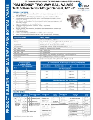
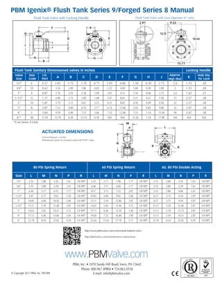

The PBM Igenix® two-way ball valves are designed for tank bottom applications, featuring a unique adjust-o-seal® for in-line valve adjustment and bubble-tight sealing capabilities. Available in sizes from 1/2” to 6”, these ASME BPE compliant valves provide options for various materials and connections, ensuring efficient drainage and easy maintenance. The product offers multiple configuration options, including actuator compatibility, various seat materials, and different polish finishes to meet diverse operational requirements.