SlideShare a Scribd company logo
1 of 22
Download to read offline
(989) 358-7000
LineshaftDrivenLive
RollerConveyors
- 169 -
Driven
Live Roller Conveyors
Lineshaft
LineshaftDrivenLive
RollerConveyors
24 Hour Shipment available on
specific sizes. Consult a sales
engineer for further information.
General Operating Principle:
General operation of the Lineshaft Driven Live Roller Conveyor
is achieved through a drive shaft that spans the full length of
the conveyor and transmits power to the rollers via a drive spool
and belt. When back pressure is applied to the conveyed
product, the spools driving the rollers will slip on the shaft,
allowing the product to accumulate with a minimum amount of
back pressure.
Applications include transportation, minimum pressure
accumulation, zero pressure accumulation and sortation.
This conveyor offers quiet operation and easy maintenance.
3/8 in. dia. Lineshaft Conveyor
Straight Slaved Sections and Drives ................ 170
Curves and Spurs ................................................. 172
1.9 in. dia. Lineshaft Conveyor
Straight Slaved Sections and Drives ................ 174
Curves and Spurs ................................................. 176
Lineshaft Conveyor Belt Transfers
Standard 90° ........................................................... 178
Reversing 90° ......................................................... 179
Bi-Directional (with drive unit) ........................... 180
Dual Lane Belt ....................................................... 181
Lineshaft Conveyor Options
Spring Assisted Lineshaft Gate ......................... 182
Herringbone ........................................................... 183
Slaved Merge .......................................................... 183
Zero Pressure Lineshaft
Driven Live Roller Conveyor ............................... 184
Dual Shaft ............................................................... 185
High Speed Pusher Device ................................. 185
Lineshaft Accessories
Power & Crossover Device ................................. 186
Blade Stops ............................................................ 186
Pneumatic Roller Brake ....................................... 188
Traffic Cop .............................................................. 188
Bolt-Up Inline Diverter ......................................... 189
Turning Wheel ........................................................ 189
External Jump Chain ............................................ 190
Conveyor Accessories ......................................... 190
Special Options..................................................... 189
(989) 358-7000
LineshaftDrivenLive
RollerConveyors
- 170 -
Lineshaft Driven Live Roller Conveyor
1 3/8 in. dia. x 16 ga. Rollers
The Lineshaft Driven Live Roller Conveyor
is a unique concept in powered conveyors.
It has the capability of accumulating
products with minimum back pressure.
Typical characteristics include quiet
operation and easy maintenance.
Standard Specifications:
Frame - 5 1/2 in. deep x 1 1/2 in. flange x 12 ga. galvanized
steel formed channel frames with bolt on end couplers.
Between Frame Widths - 13 through 28 in full one inch
increments.
Rollers - 1 3/8 in. dia. x 16 ga. galvanized rollers with 5/16 in.
hex axle and grease packed, semi-precision ball bearings.
Rollers spaced on 1 1/2 in. centers. 1 3/8 in. dia. x 18 ga.
galvanized rollers are available at speeds less than 60 FPM.
Floor Supports - Adjustable 36 in. to 48 in. from floor to top
of rollers.
Drive Shaft - 1 in. dia. steel shaft full length of conveyor.
Delrin chain coupling at bed joints.
Drive Spools - 2 in. dia. Delrin spool held in place on shaft
by “snap on” retaining clips. One drive spool drives two
rollers.
Drive Belts - 3/16 in. dia. urethane belts from drive spools
to rollers.
Spool Guard - Encloses underside of drive shaft, spools and
drive belts for full length of conveyor.
Bearings - Sealed, self-aligning, pre-lubricated ball bearings
support drive shaft.
Drive Section - Reducer and motor are mounted underneath
conveyor. Note: Motor extends beyond frame of conveyor
if between frame width is less than 20 inches. Side mounted
drive sections are also available.
Speed Reduction - “C” face speed reducer. No. 50 chain from
reducer to drive shaft.
Motor - 1/2 HP - 230/460V - 3 Phase - 60 Hz - totally enclosed,
fan cooled - 1750 RPM.
Conveying Speed - Constant 60 FPM.
Load Capacities:
- Max. load per powered roller = 10 lbs.*
- Max. driven length with single drive at center = 70 ft.
- Max. driven length per 1/4 HP = 10 ft.
- Do not exceed a 75 lb. total product load without
consulting an Omni Metalcraft Corp. Sales Engineer.
* Will be less if product has uneven or soft bottom.
sssss Minimum Back
Pressure Accumulation
sssss 16 Between Frame
Widths
sssss Single Drive Powers
Straight Sections,
Curves and Spurs
sssss Semi-Precision
Bearings for Longer Life
and Noise Reduction
sssss Reversible
sssss Safe
sssss Quiet
).sbl(thgieW
evirD
noitceS
).tf(
evirD
noitceS
).tf(
).tf(snoitceSdevalS
neewteB
emarF
htdiW
'3 '01 '1 '2 '3 '4 '5 '6 '7 '8 '9 '01
"31
"41
"51
"61
741
051
451
751
343
253
163
073
23
33
43
53
65
75
95
16
97
28
48
78
201
601
901
311
821
331
731
141
251
751
261
761
571
181
781
391
102
802
512
222
522
232
042
842
842
752
562
472
"71
"81
"91
"02
061
361
661
961
973
883
793
604
63
73
83
93
36
56
76
86
09
29
59
79
611
021
321
721
641
051
551
951
271
871
381
881
991
502
112
712
922
632
242
942
552
362
172
872
282
092
992
703
"12
"22
"32
"42
371
671
971
281
514
424
334
244
04
14
34
44
07
27
47
67
001
301
501
801
031
331
731
041
361
861
271
671
391
891
302
902
322
922
532
142
652
362
072
772
682
492
103
903
613
423
333
143
"52
"62
"72
"82
581
881
291
591
154
064
964
874
54
64
74
84
87
97
18
38
111
311
611
911
441
741
151
451
181
581
981
491
412
912
422
922
742
352
952
562
482
192
792
403
713
423
233
043
053
853
763
573
FLOW
Retaining
Clip
Drive
Shaft
Drive Belt
Tread
Roller
Drive
Spool
(989) 358-7000
LineshaftDrivenLive
RollerConveyors
- 171 -
Optional Equipment:
Keyed Spools - Spools are keyed and fit into a keyseat on the
drive shaft. Instead of slipping on the shaft, spools provide positive
drive. NOTE: Keyed spool conveyor sections cannot exceed
4 ft. long.
Speed-Up Spools - Larger diameter spools that increase speed
1.3 times the original speed.
Pneumatic Roller Brake - Air operated conveyor accessory that
stops rollers in 2 ft. or 3 ft. zones. See page 188 for details.
Blade Stops - Pneumatically or manually operated blade that pops
up between rollers in order to accumulate product. See page 186
and 187 for details.
Timing Belt Drive - Used as an option to chain drive, allowing
for quieter operation. Timing belt drive is required at a speed of
120 FPM.
Roller Centers - 3 in., 4 1/2 in. and 6 in. roller centers are also
available.
Power Crossover - 1 ft. long section that switches drive shaft from
one side of the conveyor to the other. Timing belt and chain driven
models available. See page 186 for details. Can also be used to
increase speeds.
External Jump Chain - 3 ft. long section with a jump chain that
transmits power from one conveyor line to a parallel conveyor line.
One drive can power two parallel lines. Chain driven and timing belt
driven models available. See page 190 for details. Can also be
used to increase speeds.
Conveying Speed - Constant and variable speeds from
25 to 120 FPM. AC or DC variable speed controllers available.
Urethane BeltTransfer - 3 ft.long section has an air operated
lifting device that raises urethane transfer belts above the roller
surface to transfer product off @ 90°. See pages 178,179,180 and
181 for details.
Spring Assisted Gate Section - 6 ft. section consisting of 2 ft.
fixed section and 4 ft. gate section. See page 182 for details.
Guard Rails - 1 1/2 in. wide x 2 in. high x 12 ga. galvanized steel
formed angle. One or both sides. Note: If product contacts
guard rails, product flow may be affected.
Floor Supports - Available in higher or lower height adjustments.
Ceiling Hangers - 5/8 in. dia. x 10 ft. long threaded rod with
mounting hardware.
Other Rollers - 1 3/8 in. dia. x 18 ga. or 1 3/8 in. dia. x
3/16 in. wall tubing. Closed style non-precision bearings also
available.
Motors - Single phase, drip proof, DC motors, inverter duty
motors available through 2 HP.
Electrical Controls - Start-Stop push button stations, reversing
drum switch, one direction and reversible magnetic starters.
Side Mount Drive - Allows minimum top of roller height of
10 3/4 inches. Note: Motor is vertical.
OVERALL LENGTH
1' TO 10'
SLAVED
SECTION(S)
2' TO 10'
DRIVE
SECTION
21 1/4" MIN.
T.O.R.
18 7/16"
BETWEEN FRAME WIDTH
3/16"
5 1/2" DRIVE
BELT
RETAININGCLIP
2"
1 1/2"
SPOOL
GUARD
DRIVE SPOOL
4 7/8"
2 3/4"
Model Number: Slaved Section
LSSS1.4 x 16 - __ - 1.5 - __
Length (1 ft. to 10 ft.)
Roller Description
Between Frame Width
(13 in. to 28 in.)
Roller Spacing
Model Number: Drive Section
LSDS1.4 x 16 - __ - 1.5 - __ - F __ - __ - CD -
H.P. (1/3 to 2)
Speed (25 to 120 FPM)
Speed Type
(F) = Fixed Speed
(V) = Variable Speed
Length
(2 ft. to 10 ft.)
Roller
Description
Between Frame Width
(13 in. to 28 in.)
Roller Spacing
CD = Chain Driven
TB = Timing Belt Driven
SM = Side Mount Drive
Leaveblankifdriveis
underhung
14 1/4"
SPOOLGUARD
(989) 358-7000
LineshaftDrivenLive
RollerConveyors
- 172 -
Lineshaft Driven Curve and Spur Conveyor
Curves - 1 in. to 1 1/2 in. dia. x 18 ga. Tapered Rollers
Spurs - 1 3/8 in. dia. x 16 ga. Straight Rollers
sssss 16 Between Frame Widths
sssss Curves are Transportation
Conveyors Only
sssss Slave Driven from Straight
Section or Self Powered
sssss 30°,45°,60° and 90° Curves;
30° and 45° Spurs
sssss Tapered Rollers on Curves
Lineshaft Curves and Spurs are slave driven from
lineshaft straight sections or powered by their own
drive unit. Curves allow for turns in the product
line, whereas spurs are used when product lines
converge or diverge.
Note: 30° curves have 1 ft.
tangent sections at each end.
45° CURVE
90° CURVE
DRIVE
SHAFT
U-JOINT
SHAFT
COUPLING
36"INSIDE
RADIUS
45°
36"INSIDE
RADIUS
SHAFT
COUPLING
90°
U-JOINT
DRIVE SHAFT
BETWEEN FRAME WIDTH1 1/2"
DRIVEBELT
3/16"
5 1/2"
DRIVESPOOL
SPOOLGUARD
2"
2 3/4"
Model Number:
LSSC1.4 x 18 - __ - 3 - __ - T
(T) Tapered Roller
Degree of Curve
(30°, 45°, 60° or 90°)
Roller Description
Between Frame Width
(13 in. to 28 in.)
Equivalent Roller Spacing
evruC°09 ROYEVNOC
).sbl(THGIEWneewteB
emarF
htdiW
forebmuN
srelloR
evruCno
relloR
@sretneC
enilretneC °03 °54 °06 °09
"31
"41
"51
"61
"71
23
derepaT
srelloR
"680.2
"111.2
"531.2
"061.2
"481.2
15
35
55
65
85
39
59
79
99
101
901
311
511
811
121
471
971
381
781
191
"81
"91
"02
"12
"22
"902.2
"432.2
"852.2
"382.2
"703.2
95
06
16
26
36
301
501
701
011
211
321
621
821
031
331
591
991
302
702
112
"32
"42
"52
"62
"72
"82
"233.2
"653.2
"183.2
"504.2
"034.2
"454.2
671
971
381
681
981
291
501
701
901
111
311
611
041
341
641
841
151
451
822
232
732
142
542
942
(989) 358-7000
LineshaftDrivenLive
RollerConveyors
- 173 -
45° SPUR
LEFT
HAND
RIGHT
HAND
Model Number:
LSS__ - 1.4 x 16 - __ - 1.5 - __
Between Frame Width
(13 in. to 28 in.)
Roller Description
(slaved from this end)
R = Right Hand
L = Left Hand
Roller Spacing
Angle of Spur (30° or 45°)
Optional Equipment:
Drive - Drive units can be mounted to curves and spurs to give
them power without being slave driven.
Guard Rails - 1 1/2 in. wide x 2 in. high x 12 ga. galvanized
steel formed angle. One or both sides. Note: If product
contacts guard rails, product flow may be affected.
Floor Supports - Available in higher or lower height
adjustments.
Ceiling Hangers - 5/8 in. dia. x 10 ft. long threaded rod
with mounting hardware.
Wheel Diverter - Pneumatically controlled device that
automatically diverts product from main line onto a 30° spur.
See page 189 for more details.
Traffic Cop - Controls product flow where two lines converge
eliminating product collisions. Only one line is open at a given
time. See page 188 for more details.
TurningWheel - Used on converging lines to insure proper
product orientation when product is transferred onto a main
line. See page 189 for more details.
Slaved Merge - Integral spur and straight section used
in applications where products must merge with another
conveying line. Both sections are slaved off a common drive.
See page 183 for more details.
TrueTapered Roller Curve - True tapered roller curve
available. Will require special radius or special rollers.
Standard Specifications:
Frame - 5 1/2 in. deep x 1 1/2 in. flange x 12 ga. galvanized steel
formed channel frames with bolt on end couplers. Note: Outside
rail of curve has“triple-punched”hex holes to allow skewing
of rollers which affects product tracking. Curve rollers do not
represent a true taper.
Between FrameWidths - 13 through 28 in full one inch
increments.
Curve Rollers - 1 1/2 in. dia. tapered to 1 in. dia. x 18 ga. zinc plated
rollers. Grease packed, semi-precision ball bearings.
Spur Rollers - 1 3/8 in. dia. x 16 ga. galvanized rollers on
1 1/2 in. centers. Grease packed ball bearings.
Floor Supports - Adjustable 36 in. to 48 in. from floor to top
of rollers.
Slave Driven - Curves or spurs are slave driven from the drive
shaft of a lineshaft straight section. Shafts are coupled by a Delrin
chain coupling at bed joints.
Drive Shaft - 1 in. dia. steel shaft with universal joints as
necessary.
Drive Spools - 2 in. dia. Delrin spool held in place on shaft
by “snap on” retaining clips. One drive spool drives two rollers.
Drive Belts - 3/16 in. dia. high tension urethane belt from
drive spools to rollers.
Spool Guard - Encloses underside of drive shaft, spools and drive
belts.
Bearings - Sealed, pre-lubricated, self-aligning ball bearings
on drive shaft.
Load Capacities - Same roller capacity as lineshaft 1.4 straight
sections.
DRIVE
SHAFT*
“B”
“C”
SHAFT
COUPLING
“A”
45°
ROYEVNOCRUPS°03 ROYEVNOCRUPS°54
neewteB
emarF
htdiW
”A“
).ni(
”B“
).ni(
”C“
).ni(
.tW
).sbl(
”A“
).ni(
”B“
).ni(
”C“
).ni(
.tW
).sbl(
"31
"41
"51
"61
"71
61/3103
4/373
4/373
4/373
61/1144
63
84
84
84
84
21
12
12
81
51
74
37
67
77
87
8/182
8/182
8/182
8/323
8/323
63
63
63
63
63
12
12
12
81
81
65
95
26
26
46
"81
"91
"02
"12
"22
61/1144
61/1144
61/1144
2/135
2/135
84
84
84
06
06
51
21
21
12
81
08
08
28
711
811
8/323
61/963
61/963
61/993
61/3104
63
63
63
63
63
81
51
51
51
21
76
66
86
17
07
"32
"42
"52
"62
"72
"82
2/135
61/985
61/985
61/985
61/985
61/376
06
06
06
06
06
27
81
51
51
21
21
12
021
121
421
421
621
761
61/3104
61/3104
61/154
61/154
61/154
61/594
63
63
84
84
84
84
21
21
12
12
12
81
27
47
311
511
911
811
* Dark shaft indicates
positive drive spools
Note: Minimum recommended product
length to converge or diverge product is 12".
(989) 358-7000
LineshaftDrivenLive
RollerConveyors
- 174 -
Lineshaft Driven Live Roller Conveyor
1.9 in. dia. x 16 ga. Rollers
sssss Minimum
Back Pressure
Accumulation
sssss 27 Between Frame
Widths
sssss Reversible
sssss Single Drive Powers
Straight Sections,
Curves and Spurs
sssss Safe
sssss Quiet
Standard Specifications:
Frame - 5 1/2 in. deep x 1 1/2 in. flange x 12 ga. galvanized
steel formed channel frames with bolt on end couplers.
Between FrameWidths - 13 through 39 in full one inch
increments.
Rollers - 1.9 in. dia. x 16 ga. galvanized rollers with 7/16 in.
hex axle and grease packed ball bearings. Rollers spaced on
3 in. centers.
Drive Shaft - 1 in.dia.steel shaft full length of conveyor. Delrin
chain coupling at bed joints.
Drive Spools - 2 in. dia. Delrin spool held in place on shaft by
“snap-on” retaining clips.
Drive Belts - 3/16 in. dia. urethane belts from drive spools
to rollers.
Spool Guard - Encloses underside of drive shaft, spools and
drive belts for full length of conveyor.
Bearings - Sealed, self-aligning, pre-lubricated ball bearings
support drive shaft.
Drive Section - Reducer and motor mounted underneath
conveyor. Note: Motor extends beyond frame of conveyor if
between frame width is less than 20 in.
Speed Reduction - “C” face speed reducer. No. 50 chain from
reducer to drive shaft.
Motor - 1/2 HP - 230/460V - 3 Phase - 60 Hz - totally enclosed,
fan cooled - 1750 RPM.
Conveying Speed - Constant 60 FPM.
Load Capacities:
- Max. load per powered roller = 15 lbs.*
- Max. driven length with single drive at center = 120 ft.
- Max. driven length per 1/4 HP = 20 ft.
- Do not exceed a 75 lb. total product load without
consulting an Omni Metalcraft Corp.Sales Engineer.
* Will be less if product has uneven or soft bottom.
).sbl(thgieW
evirD
noitceS
).tf(
evirD
noitceS
).tf(
).tf(snoitceSdevalS
neewteB
emarF
*htdiW
'3 '01 '1 '2 '3 '4 '5 '6 '7 '8 '9 '01
"31
"41
"51
"61
"71
"81
"91
"02
"12
431
731
931
241
541
741
051
251
551
382
292
792
603
513
023
923
433
343
92
03
13
23
33
43
53
53
63
05
25
35
55
75
85
95
06
26
17
37
57
77
08
18
48
58
88
19
59
79
001
301
501
901
111
411
411
911
121
521
031
231
731
931
341
531
041
341
841
351
651
161
461
961
651
261
561
171
771
081
681
981
591
971
681
981
691
302
702
412
712
422
991
702
112
912
722
132
832
242
052
022
922
332
242
052
452
362
762
672
"22
"32
"42
"52
"62
"72
"82
"92
"03
751
061
461
661
861
171
471
671
871
843
753
663
173
673
583
493
993
404
73
83
93
04
04
14
34
34
44
36
56
76
86
96
17
37
47
57
09
29
59
69
89
001
301
401
601
611
911
321
521
621
031
331
531
731
641
051
451
751
951
361
861
071
271
271
771
281
581
881
391
891
102
402
891
402
012
312
612
222
822
132
532
822
532
242
542
942
652
362
662
072
452
262
072
472
872
582
392
792
103
082
982
792
203
603
513
323
823
233
"13
"23
"33
"43
"53
"63
"73
"83
"93
181
381
681
881
191
391
691
891
202
314
814
724
234
144
644
554
064
964
54
54
74
74
84
94
05
15
25
77
87
08
18
28
38
58
68
88
901
011
311
411
711
811
121
221
521
041
241
641
841
151
351
651
851
261
771
081
481
681
091
391
791
991
402
902
112
712
912
522
722
232
532
042
142
442
052
352
952
262
862
172
772
772
182
882
192
892
203
903
213
913
903
313
123
523
233
633
443
843
653
143
543
453
853
763
173
083
483
393
The Lineshaft Driven Live Roller Conveyor is a
unique concept in powered conveyors. It has the
capability of accumulating products with minimum
back pressure. Typical characteristics include quiet
operation and easy maintenance.
(989) 358-7000
LineshaftDrivenLive
RollerConveyors
- 175 -
OVERALL LENGTH
1' TO 10'
SLAVED
SECTION(S)
2' TO 10'
DRIVE
SECTION
14 1/4"
21 1/4" MIN.
T.O.R.
18 7/16"
1/4"
5 1/2" DRIVE
BELT
RETAININGCLIP
2"
1 1/2"
SPOOL
GUARD
DRIVESPOOL
4 7/8"
2 3/4"
Optional Equipment:
Keyed Spools - Spools are keyed and fit into a keyseat on the drive
shaft. Instead of slipping on the shaft, spools provide positive drive.
NOTE: Keyed spool conveyor sections cannot exceed 4 ft.
long.
Speed-Up Spools - Larger diameter spools that increase speed 1.3
times the original speed.
Pneumatic Roller Brake - Air operated conveyor accessory that
stops rollers in 2 ft. or 3 ft. zones. See page 188 for details.
Blade Stops - Pneumatically or manually operated blade that pops
up between rollers in order to accumulate product. See page 186
and 187 for details.
Timing Belt Drive - Used as an option to chain drive, allowing for
quieter operation. Timing belt drive is required at speeds from 120 to
180 FPM.
Roller Centers - 3 in., 4 in., 6 in. and 8 in. roller centers are also
available.
Power Crossover - 1 ft. long section that switches drive shaft from
one side of the conveyor to the other. Timing belt and chain driven
models available. See page 186 for details. Can also be used to
increase speeds.
External Jump Chain - 3 ft. long section with a jump chain that
transmits power from one conveyor line to a parallel conveyor line.
One drive can power two parallel lines. Chain driven and timing belt
driven models available. See page 190 for details. Can also be used
to increase speeds.
Floor Supports - Available in higher or lower height adjustments.
Conveying Speed - Constant and variable speeds from 25 to
180 FPM. AC or DC variable speed controllers available.
Urethane BeltTransfer - 3 ft.long section has an air operated
lifting device that raises urethane transfer belts above the roller
surface to transfer product off @ 90°. See pages 178, 179, 180
and 181 for details.
Spring Assisted Gate Section - 6 ft. section consisting of
2 ft. fixed section and 4 ft. gate section. See page 182 for
details.
Guard Rails - 1 1/2 in. wide x 2 in. high x 12 ga. galvanized
steel formed angle. One or both sides. Note: If product
contacts guard rails, product flow may be affected.
Ceiling Hangers - 5/8 in. dia. x 10 ft. long threaded rod with
mounting hardware.
Other Rollers - 1.9 in. dia. x 13 ga. or 1.9 in. dia. x .145 wall,
semi-precision and precision bearings available for extended
life and noise reduction.
Motors - Single phase, drip proof, DC motors, inverter duty
motors available through 2 HP.
Electrical Controls - Start-Stop push button stations,
reversing drum switch, one direction and reversible magnetic
starters.
Side Mount Drive - Allows minimum top of roller height of
10 3/4 inches. Note: Motor is vertical.
SPOOLGUARD
Model Number: Slaved Section
LSSS1.9 x 16 - __ - - __
Length (1 ft. to 10 ft.)
Roller Description
Between Frame Width
(13 in. to 39 in.)
Roller Spacing
Model Number: Drive Section
LSDS1.9 x 16 - __ - - __ - F __ - __ - CD -
H.P. (1/3 to 2)
Speed (25 to 180 FPM)
Speed Type
(F ) = Fixed Speed
(V) = Variable Speed
Length
(2 ft. to 10 ft.)
Roller
Description
Between Frame Width
(13 in. to 39 in.)
Roller Spacing
CD = Chain Driven
TB = Timing Belt Driven
SM = Side Mount Drive
Leave blank if drive is
underhung
BETWEENFRAMEWIDTH
(989) 358-7000
LineshaftDrivenLive
RollerConveyors
- 176 -
Lineshaft Driven Curve and Spur Conveyor
Curves - 1 11/16 in. to 2 1/2 in. dia. x 14 ga. Tapered Rollers
Spurs - 1.9 in. dia. x 16 ga. Straight Rollers
sssss 27 Between Frame Widths
sssss Curves are Transportation
Conveyor Only
sssss Slave Driven from Straight
Section or Self Powered
sssss 30°, 45°, 60° and 90° Curves;
30° and 45° Spurs
sssss Tapered Rollers on Curves
Lineshaft Curves and Spurs are slave driven from
lineshaft straight sections and are powered by
their own drive unit. Curves allow for turns in
the product line, whereas spurs are used when
product lines converge or diverge.
45° CURVE
90° CURVE
DRIVE
SHAFT
U-JOINT
SHAFT
COUPLING
36" INSIDE
RADIUS
45°
36" INSIDE
RADIUS
SHAFT
COUPLING
90°
U-JOINT
Note: 30° curves have 1 ft.
tangent sections at each end.
DRIVE SHAFT
BETWEEN FRAME WIDTH1 1/2"
DRIVE BELT
1/4"
5 1/2"
DRIVE SPOOL
SPOOL GUARD
2"
2 3/4"
Model Number:
LSSC1.9 x 16 - __ - 3 - __ - T
T= Tapered Roller
Degree of Curve
(30°, 45°, 60° or 90°)
Roller Description
Between Frame Width
(13 in. to 39 in.)
Equivalent Roller Spacing
evruC°09 RELLORDEREPAT
neewteB
emarF
htdiW
srelloR
°09reP
evruC
relloR
@sretneC
enilretneC
).sbL(thgieW
°03 °54 °06 °09
"31
"41
"51
"61
"71
42
derepaT
srelloR
"187.2
"418.2
"748.2
"088.2
"319.2
621
031
231
631
041
98
29
39
69
99
121
521
721
131
631
491
991
302
802
412
"81
"91
"02
"12
"22
"549.2
"879.2
"110.3
"340.3
"670.3
241
641
841
251
551
101
401
501
801
011
831
241
441
841
151
812
322
722
332
632
"32
"42
"52
"62
"72
"901.3
"241.3
"471.3
"702.3
"042.3
851
261
461
761
071
311
611
711
911
221
551
951
161
461
861
242
842
152
452
062
"82
"92
"03
"13
"23
"272.3
"503.3
"833.3
"173.3
"304.3
471
771
971
381
581
521
721
821
131
331
271
471
771
181
381
662
962
372
972
282
"33
"43
"53
"63
"73
"634.3
"964.3
"205.3
"435.3
"765.3
281
581
981
191
591
631
831
041
241
541
781
981
391
691
002
882
192
792
003
603
"83
"93
"006.3
"236.3
791
102
741
051
202
602
903
513
(989) 358-7000
LineshaftDrivenLive
RollerConveyors
- 177 -
45° SPUR
LEFT
HAND
RIGHT
HAND
Optional Equipment:
Drive - Drive units can be mounted to curves and spurs rather
than being slave driven.
Guard Rails - 1 1/2 in. wide x 2 in. high 12 ga. galvanized steel
formed angle. One or both sides. Note: If product contacts
guard rails, product flow may be affected.
Floor Supports - Available in higher or lower height
adjustments.
Ceiling Hangers - 5/8 in. dia. x 10 ft. long threaded rod with
mounting hardware.
Wheel Diverter - Pneumatically controlled device that
automatically diverts product from main line onto a 30° spur.
See page 189 for more details.
Traffic Cop - Controls product flow where two lines converge
eliminating product collisions. Only one line is open at a given
time. See page 188 for more details.
TurningWheel - Used on converging lines to insure proper
product orientation when product is transferred onto a main
line. See page 189 for more details.
Slaved Merge - Integral spur and straight section used in
applications where products must merge with another
conveying line. Both sections are slaved off a common drive.
See page 183 for more details.
Standard Specifications:
Frame - 5 1/2 in. deep x 1 1/2 in. flange x 12 ga. galvanized steel
formed channel frames with bolt on end couplers. Note: Outside
rail of curve has “triple-punched”hex holes to allow skewing
of rollers which affects product tracking. Curve rollers do not
represent a true taper.
Between FrameWidths - 13 through 39 in full one inch
increments.
Curve Rollers - 2 1/2 in. dia. tapered to 1 11/16 in. dia. x 14 ga. zinc
plated rollers. Grease-packed ball bearings.
Spur Rollers - 1.9 in. dia. x 16 ga. galvanized rollers with 7/16 hex
axle on 3 in. centers. Grease-packed ball bearings.
Floor Supports - Adjustable 36 in. to 48 in. from floor to top
of rollers.
Slave Driven - Curves or spurs are slave driven from the drive shaft
of a lineshaft straight section. Shafts are coupled by a Delrin chain
coupling at bed joints.
Drive Shaft - 1 in. dia. steel shaft with universal joints as
necessary.
Drive Spools - 2 in. dia. Delrin spool held in place on shaft by
“snap on” retaining clips.
Drive Belts - 3/16 in. dia. high tension urethane belt from drive
spools to rollers.
Spool Guard - Encloses underside of drive shaft, spools and drive
belts.
Bearings - Sealed, pre-lubricated, self-aligning ball bearings
on drive shaft.
Load Capacities - Same roller capacity as lineshaft 1.9 straight
sections.
DRIVE
SHAFT*
“B”
“C”
SHAFT
COUPLING
“A”
45°
* Dark shaft indicates
positive drive spools
Model Number:
LSS__ - 1.9 x 16 - __ - 3 - __
Angle of Spur (30° or 45°)
Roller Spacing
Between Frame Width
(13 in. to 39 in.)
Roller Description
R = Right Hand
L = Left Hand
Note: Minimum product length recommended
to converge or diverge product is 12".
RUPS°03 RUPS°54
neewteB
emarF
htdiW
”A“
).ni(
”B“
).ni(
”C“
).ni(
.tW
).sbl(
”A“
).ni(
”B“
).ni(
”C“
).ni(
.tW
).sbl(
"31
"41
"51
"61
"71
61/3103
4/373
4/373
4/373
61/1144
63
84
84
84
84
21
12
12
81
51
23
74
94
84
84
8/182
8/182
8/182
8/323
8/323
63
63
63
63
63
12
12
12
81
81
73
83
04
93
04
"81
"91
"02
"12
"22
61/1144
61/1144
61/1144
2/135
2/135
84
84
84
06
06
51
21
21
12
81
94
94
05
07
96
8/323
61/963
61/963
61/993
61/3104
63
63
63
63
63
81
51
51
51
21
24
04
24
44
14
"32
"42
"52
"62
"72
2/135
61/985
61/985
61/985
61/985
06
06
06
06
06
81
51
51
21
21
17
07
27
17
37
61/3104
61/3104
61/154
61/154
61/154
63
63
84
84
84
21
21
12
12
12
34
54
56
76
07
"82
"92
"03
"13
"23
61/376
61/376
61/376
8/327
8/327
27
27
27
27
27
12
81
81
51
51
69
69
89
79
99
61/594
61/594
61/594
61/935
61/935
84
84
84
84
84
81
81
81
51
51
76
96
27
86
17
"33
"43
"53
"63
"73
8/327
8/327
61/118
61/118
61/118
27
27
48
48
48
21
21
12
81
81
89
001
721
621
921
61/935
8/775
8/775
8/775
61/126
84
84
84
84
06
51
21
21
21
12
37
96
27
47
001
"83
"93
2/148
2/148
48
48
51
51
821
031
61/126
61/126
06
06
12
12
301
601
(989) 358-7000
LineshaftDrivenLive
RollerConveyors
- 178 -
Urethane Belt Transfer Device - Standard Flow
1 3/8 in. or 1.9 in. dia. Rollers
Transfer Belt Height - Factory assembled to raise 3/8 in.above
conveying surface, but adjustable to 3/4 in.
Slave Driven - Unit is slave driven from the drive shaft of a
lineshaft straight section. Shafts are coupled by a Delrin chain
coupling at bed joints.
Air Bag - No-maintenance air bag provides approximately 100 to
600 lbs. force from 45 to 100 PSI respectively.
Air Requirements - 45 PSI to 100 PSI. Pressure should be
regulated to minimum PSI required to actuate device at installation.
Valve - Single solenoid 4-way valve. 1/4 in. NPT valve ports.
Requires maintained electrical signal of 115V - 1 Phase - 60 Hz
Filter/Regulator - Supplied for main air supply line - 3/8 in. NPT
port.
Options:
• Drive Unit • Timing Belt Jump Chain
• 5th Belt on Center • End Guard Kit
• Optional Belt Centers • Blade Stop Installed
• Roller Brake Installed
The Belt Transfer Device is slaved from other lineshaft sections. Transfer belts are raised
pneumatically above conveying surface to transfer product at 90° onto another conveyor line.
NOTE: This is a slaved unit. Speed and direction of the
product being transferred is dictated by the speed and
direction of the shaft from which it is slaved. Minimum
recommended product width = 15". If product is less
than 15" wide or not long enough to contact the four
transfer belts, consult an Omni sales engineer for pricing
on extended belts or special belt centers.
Standard Specifications:
Load Capacity - Maximum package weight: 75 lbs.
Frame - 11 in. deep x 1 1/2 in. flange x 12 ga. galvanized steel
formed channel frames with bolt-on end couplers.
Between FrameWidths - 13 through 28 in full one inch
increments for 1 3/8 in.roller. 13 through 39 in full one inch
increments for 1.9 in.roller.
Rollers - 1 3/8 in. dia. galvanized rollers with 5/16 in. hex axle
on 1 1/2 in. centers or 1.9 in. dia. x 16 ga. galvanized rollers with
7/16 hex axle on 3 in. centers. Both have grease-packed ball
bearings.
Transfer Belts - Four powered 3/8 in.dia.urethane belts are
pneumatically lifted above roller surface to transfer product off
@ 90°. See chart for belt centers.
Jump Chain - Transmits power from power shaft to idler shaft.
Available in chain driven & timing belt driven models.
Transfer Belt Centers -
Model Number:
LSSB____ - __ - CD - STB
CD = Chain Driven
TB = Timing Belt Driven
Between Frame Width
(13 in. to 39 in.) for 1.9
(13 in. to 28 in.) for 1 3/8
Roller Description
(1.4 x 16) 1 3/8 in. dia. x 16 ga.
(1.9 x 16) 1.9 in. dia. x 16 ga.
Standard Transfer Belts
–
36"
B A
A
B C
A
FLOW
BETWEENFRAMEWIDTH
FLOW
NOTE: Min. Top of Roller = 11 1/4 in.
Shaft
Rotation
EndView
D
11"
1 7/8" (Typ.)
SDRADNATSREFSNARTTLEB
relloR
retemaiD A B C D
8/31 8/57 2/14 2/11 61/3
9.1 2/101 2/13 3 4/1
(989) 358-7000
LineshaftDrivenLive
RollerConveyors
- 179 -
ZeroPressureLineshaft
DrivenLiveRollerConveyors
GravityConveyorsBeltConveyors
Urethane Belt Transfer Device - Reverse Flow
1 3/8 in. or 1.9 in. dia. Rollers
Standard Specifications:
Load Capacity - Maximum package weight: 75 lbs.
Frame - 11 in. deep x 1 1/2 in. flange x 12 ga. galvanized steel
formed channel frames with bolt on end couplers.
Between FrameWidths - 13 through 28 in full one inch
increments for 1 3/8 in.roller. 13 through 39 in full one inch
increments for 1.9 in.roller.
Rollers - 1 3/8 in. dia. galvanized rollers with 5/16 in. hex. axle on
1 1/2 in. centers or 1.9 in. dia. x 16 ga. galvanized rollers with 7/16
hex. axle on 3 in. centers. Both have grease-packed ball bearings.
Transfer Belts - Four powered 3/8 in.dia.urethane belts are
pneumatically lifted above roller surface. See chart for belt
centers.
Jump Chain - Transmits power from power shaft to idler shaft.
Available in chain driven and timing belt driven models.
Transfer Belt Centers -
Transfer Belt Height - Factory assembled to raise 3/8 in.
above conveying surface, but adjustable to 3/4 in.
Slave Driven - Unit is slave driven from the drive shaft of a
lineshaft straight section. Shafts are coupled by a Delrin chain
coupling at bed joints.
Air Bag - No maintenance air bag provides approximately
100 to 600 lbs. force from 45 to 100 PSI respectively.
Air Requirements - 45 PSI to 100 PSI. Pressure should be
regulated to minimum PSI required to actuate device at
installation.
Valve - Single solenoid 4-way valve. 1/4 in. NPT valve ports.
Requires maintained electrical signal of 115V - 1 Ph. - 60 Hz.
Filter/Regulator - Supplied for main air supply line - 3/8 in. NPT
port.
Options:
• Drive Unit • Timing Belt Jump Chain
• 5th Belt on Center • End Guard Kit
• Optional Belt Centers • Blade Stop Installed
• Roller Brake Installed
SectionA-A
–
Shaft
Rotation
Model Number:
LSSB____ - __ - CD - RTB
CD = Chain Driven
TB = Timing Belt Driven
Between Frame Width
(13 in. to 28 in.) for 1 3/8
(13 in. to 39 in.) for 1.9
Roller Description
(1.4 x 16) 1 3/8 in. dia. x 16 ga.
(1.9 x 16) 1.9 in. dia. x 16 ga.
Reverse Transfer Belts
D
11"
A
A
36"
A BB
BETWEENFRAMEWIDTH
FLOW
SDRADNATSREFSNARTTLEB
relloR
retemaiD A B C D
8/31 8/57 2/14 2/11 61/3
9.1 2/101 2/13 3 4/1
FLOW
1 7/8" (Typ.)
NOTE: This is a slaved unit. Speed and direction of the
product being transferred is dictated by the speed and
direction of the shaft from which it is slaved. Minimum
recommended product width = 15". If product is less than
15" wide or not long enough to contact the four transfer
belts, consult an Omni sales engineer for pricing on
extended belts or special belt centers.
NOTE: Min. Top of Roller = 11 1/4 in.
The Belt Transfer Device is slaved from other lineshaft sections. Transfer belts are raised
pneumatically above conveying surface to transfer product at 90° onto another conveyor line.
Product transfers opposite that of device on page 178 even though shaft rotation is the same.
C
(989) 358-7000
LineshaftDrivenLive
RollerConveyors
- 180 -
Urethane Belt Transfer Device - Bi-Directional
1 3/8 in. or 1.9 in. dia. Rollers
SectionA-A
This Belt Transfer Device’s tread rollers are slaved from other lineshaft sections. Transfer belts
are independently powered by a separate drive and are pneumatically raised above conveying
surface to transfer products at 90°, in either direction, onto another conveyor line.
Speed Reduction - “C” face speed reducer. No. 50 chain
from reducer to drive shaft.
Filter/Regulator - Supplied for main air supply line - 3/8 in.
NPT port.
Motor - 1/2 HP - 230/460V - 3 Phase - 60 Hz - totally enclosed, fan
cooled - 1750 RPM.
Transfer Belt Drive Sheaves - Positively driven independent
sheaves power the transfer belts.
Air Bag - No-maintenance air bag provides approximately
270 to 600 lbs. force from 45 to 100 PSI respectively.
Air Requirements - 45 PSI to 100 PSI. Pressure should
be regulated to minimum PSI required to actuate device at
installation.
Valve - Single solenoid 4-way valve. 1/4 in. NPT valve ports.
Requires maintained electrical signal of 115V - 1 Phase - 60 Hz.
Options:
• Drive Unit • Timing Belt Jump Chain
• 5th Belt on Center • End Guard Kit
• Optional Belt Centers • Blade Stop Installed
NOTE: Transfer belts are driven independent of lineshaft.
Lineshaft is slaved from adjoining section to power rollers.
Minimum recommended product width = 15". Bi-directional
transfers are not available at widths less than 16". If product
is less than 15" wide or not long enough to contact the four
transfer belts, consult an Omni sales engineer for pricing on
extended belts or special belt centers.
B
36"
B
A
A
BETWEENFRAMEWIDTH
FLOW
FLOW
C
FLOW
Standard Specifications:
Load Capacity - Maximum package weight: 75 lbs.
Frame - 11 in. deep x 1 1/2 in. flange x 12 ga. galvanized steel
formed channel frames with bolt on end couplers.
Between FrameWidths - 16 through 28 in full one inch
increments for 1 3/8 in. roller. 16 through 39 in full one inch
increments for 1.9 in. roller.
Rollers - 1 3/8 in. dia. galvanized rollers with 5/16 in. hex. axle on
1 1/2 in. centers or 1.9 in. dia. x 16 ga. galvanized rollers with
7/16 hex. axle on 3 in. centers. Both have grease-packed ball
bearings.
Transfer Belts - Four powered 3/8 in.dia. urethane belts are
pneumatically lifted above roller surface. See chart for belt
centers.
Transfer Belt Height - Factory assembled to raise 3/8 in.above
conveying surface, but adjustable to 3/4 in.
Slave Driven - Rollers are slave driven from the drive shaft of a
lineshaft straight section. Shafts are coupled by a Delrin chain
coupling at bed joints.
Transfer Belt Centers -
CD = Chain Driven
TB = Timing Belt Driven
Between Frame Width
(16 in. to 28 in.) for 1 3/8
(16 in. to 39 in.) for 1.9
A
SDRADNATSREFSNARTTLEB
relloR
retemaiD A B C D
8/31 8/57 2/14 2/11 61/3
9.1 2/101 2/13 3 4/1
Model Number:
LSDB - __ - __
Roller Description
(1.4 x 16) 1 3/8 in. dia. x 16 ga.
(1.9 x 16) 1.9 in. dia. x 16 ga.
D1 7/8" (Typ.)
11"
23 1/4" MIN.
T.O.R.
(989) 358-7000
LineshaftDrivenLive
RollerConveyors
- 181 -
Urethane Belt Transfer Device - Dual Lane
1 3/8 in. or 1.9 in. dia. Rollers1 3/8 in. dia. x 18 ga. Rollers
Standard Specifications:
Load Capacity - Maximum package weight: 75 lbs.
Frame - 11 in. deep x 1 1/2 in. flange x 12 ga. galvanized
steel formed channel frames with bolt-on end couplers.
Between FrameWidths - 13 through 28 in full one inch increments
for 1 3/8 in. roller. 13 through 39 in full one inch increments for 1.9 in.
roller.
Between Lane Dimension - 5 through 15 in full one inch
increments.
Rollers - 1 3/8 in. dia. galvanized rollers with 5/16 in. hex. axle on
1 1/2 in. centers or 1.9 in. dia. x 16 ga. galvanized rollers with
7/16 hex. axle on 3 in. centers. Both have grease-packed ball
bearings.
Transfer Belts - Four powered 3/8 in.dia.urethane belts are
pneumatically lifted above roller surface. See chart for belt centers.
Jump Chain - Transmits power from one lane to the next lane.
Available in chain driven and timing belt driven models.
Transfer Belt Centers -
Transfer Belt Height - Factory assembled to raise 3/8 in.
above conveying surface, but adjustable to 3/4 in.
Slave Driven - Unit is slave driven from the drive shaft of a
lineshaft straight section. Shafts are coupled by a Delrin chain
coupling at bed joints. Both lanes are powered by a common
drive.
Air Bag - No-maintenance air bag provides approximately
100 to 600 lbs.force from 45 to 100 PSI respectively.
Air Requirements - 45 PSI to 100 PSI. Pressure should be
regulated to minimum PSI required to actuate device at
installation.
Valve - Single solenoid 4-way valve. 1/4 in.NPT valve ports.
Requires maintained electrical signal of 115V - 1 Phase - 60 Hz.
Filter/Regulator - Supplied for main air supply line - 3/8 in.
NPT port.
Options:
• Drive Unit • Roller Brake Installed
• 5th Belt on Center • Timing Belt Jump Chain
• Optional Belt Centers • End Guard Kit
A Dual Lane Belt Transfer Device is slaved from other lineshaft sections. Transfer belts are pneumatically
raised above the conveying surface to transfer product at 90° onto another parallel conveying line.
SDRADNATSREFSNARTTLEB
relloR
retemaiD A B C D
8/31 8/57 2/14 2/11 61/3
9.1 2/101 2/13 3 4/1
OVERALLBETWEENFRAMEWIDTH
BETWEENFRAMEWIDTH
BETWEEN LANE
DIMENSION
MIN=5"/MAX=15"
A
36"
A
BETWEENFRAMEWIDTH
1 1/2"
NOTE: This is a slaved unit. Speed and direction of the product
being transferred is dictated by the speed and direction of the shaft
from which it is slaved. If product is not long enough to contact the
four transfer belts, consult an Omni sales engineer for pricing on
special belt centers.
B B
A
C
12 1/2"
BETWEEN FRAME WIDTH BETWEEN FRAME WIDTH
BETWEEN
LANES
5" MIN
15" MAX
11"
1 7/8"1 7/8"
12 3/4" MINIMUM
TOPOFROLLER
SECTION A-A STANDARD FLOW TRANSFER(STB)
SECTION A-A REVERSE FLOW TRANSFER (RTB)
Model Number:
LSBB - __ - - __ - __
Transfer Type
RTB = Reverse Flow Belt Transfer
STB = Standard Flow Belt Transfer
CD = Chain Driven
TB = Timing Belt Driven
Roller Description
(1.4 x 16) 1 3/8 in. dia. x 16 ga.
(1.9 x 16) 1.9 in. dia. x 16 ga.
Between Frame Width
(13 in. to 28 in.) for 1.4
(13 in. to 39 in.) for 1.9 Between Lanes
5 in. min./15 in. max.
BETWEEN
LANES
5" MIN
15" MAX
BETWEEN FRAME WIDTH
1 7/8"
1 1/2"
12 1/2"
11"
BETWEEN FRAME WIDTH
1 7/8"
12 3/4" MINIMUM
TOPOFROLLER
(989) 358-7000
LineshaftDrivenLive
RollerConveyors
- 182 -
Spring Assisted Gate
1 3/8 in. dia. or 1.9 in. dia. Rollers
Standard Specifications:
Frame - 5 1/2 in. deep x 1 1/2 in. flange x 10 ga. painted steel
formed channel frames with welded steel spreaders. Overall
length is 6 ft. which includes a 2 ft. stationary section and 4 ft.
gate section. Painted silver.
Between FrameWidths - 13 through 28 in full one inch
increments for 1 3/8 in.roller. 13 through 39 in full one inch
increments for 1.9 in.roller.
Rollers - 1 3/8 in. dia. x 16 ga. galvanized rollers with 5/16 in.
hex axle on 1 1/2 in. centers or 1.9 in. dia. x 16 ga. galvanized
rollers with 7/16 hex axle on 3 in. centers. Both have grease-
packed ball bearings.
Springs - Provide counter-balancing forces to assist in raising
and lowering of the gate.
Coupling - Disengages to stop driving gate section when
raised and re-engages when gate section is lowered.
Drive Spools - 2 in. dia. Delrin spools held in place on shaft by
“snap on” retaining clips.
Drive Belts - 3/16 in. dia. urethane belts from drive spools to
rollers.
Spool Guard - Encloses underside of drive shaft, spools and
drive belts for full length of conveyor.
Option - Pivot Leg Support.
LEFT HANDRIGHT HAND
FLOW
HANDLE
DRIVE
SHAFT
DRIVE
SHAFT HANDLE
FLOW
CLEARANCE=
3911/16"
(APPROX.)
Model Number:
LSSG1.9 x 16 - ___ - 3 - __
RH = Right Hand
LH = Left Hand
Between Frame Width
(13 in. to 39 in.) for 1.9
(13 in. to 28 in.) for 1.4
FLOW
³³³³³
INFEED
END
18" MIN.
T.O.R.
12"
5 1/2"
24"
3/4"
47 1/4"
³³³³³
Lineshaft Spring Assisted Gates are slaved from other lineshaft sections at the infeed end.
Gate sections provide easy access for personnel and equipment. They rest against a support
which is mounted to the next conveyor in line. Power does not continue through to the end of
the gate. A new drive must be supplied for conveyors beyond the end of the gate section.
(989) 358-7000
LineshaftDrivenLive
RollerConveyors
- 183 -
Lineshaft Driven Live Roller Conveyor Options
Slaved Merge
1.9 in. dia. x 16 ga. Rollers or 1 3/8 in. dia. x 16 ga. Rollers
The Lineshaft Driven, Slaved Merge Conveyor is an integral spur and straight section used in
applications where products must merge with another conveying line. Both sections are slaved off a
common drive.
Herringbone
1.9 in. dia. x 16 ga. Rollers or 1 3/8 in. dia. x 16 ga. Rollers
The Lineshaft Driven, Herringbone Conveyor consists of (2) parallel lanes powered by a common drive.
Rollers are skewed in order to center product. Products can infeed from parallel lanes and discharge into a
single lane.
FLOW
A
A
DRIVE
SHAFT
OVERALL BETWEEN
FRAME WIDTH
B.F. B.F.
2 3/4"2 3/4"
5 1/2"
2"
7 3/4"
VIEW A-A
DRIVESHAFT
30° OR 45°
B.F.
U-JOINT
24 (REF)
B.F.
* Dark shaft indicates
positive drive spools
FLOW
FLOW
(989) 358-7000
LineshaftDrivenLive
RollerConveyors
- 184 -
Standard Specifications:
Frame - 5 1/2 in. x 1 1/2 in. x 12 ga. galvanized formed steel
channel frames with bolt-on end couplers.
Accumulation Zones - 24 in. long is standard. 18 in., 30 in. and
36 in. zone lengths available. Each zone is controlled by air logic.
Between FrameWidths - 13 in.to 39 in.in full inch increments.
Rollers - 1.9 in. x 16 ga. galvanized rollers with 7/16 in. hex axle
and grease packed bearings. Rollers spaced on 3 in. centers.
Sensing Roller - 7/8 in.dia.x 18 ga.wall aluminum roller.
(One roller in each Accumulation Zone.) Minimum product
weight required to depress trigger roller is 5 lbs.
Zero Pressure Options: 1 3/8 in. x 16 ga. dia. galvanized rollers
on 1 1/2 in. centers, slug release, electric sensor instead of
sensor rollers.
Conveying Speed - Constant 60 FPM. Other constant and
variable speeds available.
Speed Reduction - Sealed worm gear “C”face speed reducer.
No. 50 chain from reducer to drive shaft.
Motor - 1/2 HP-230/460V-3 Ph-60 Hz.-totally enclosed - fan cooled.
Maximum HP available is 2 HP.
Air Requirements - Minimum 30 PSI on main air supply line.
Filter/ Regulator/ Lubricator - Supplied for main air supply line -
3/8 in. NPT port.
Floor Supports - Adjustable 36 in. to 48 in. from floor to top of rollers.
Other heights available.
Drive - Mounted underneath with a minimum 23 1/4 in.top of roller.
If between frame dimension is less than 20 in., motor will extend
beyond frame of conveyor. Side mounted drives are available with
a minimum 12 3/4 in.top of roller.
Electrical Controls - 115V-1 Ph-60 Hz.solenoid valve in discharge
zone to override air logic. Limit switch is also supplied to revert
control back to air logic once the product is clear.
Roller and Drive Capacity - 1.9 in. dia. maximum load - 15 lbs. per
driven roller. Maximum driven length with single drive @ center -
120 ft. 1 3/8 in.dia.maximum load - 10 lbs.per driven roller. Maximum
driven length with single drive @ center - 70 feet for 1.4 rollers.
General Operation Procedure: “Cascade Release”
The lineshaft driven, zero pressure accumulation conveyor is divided into individual brake zones. The brake zones
are controlled by air logic. The rollers in a given brake zone will stop when their corresponding pneumatic brake is
actuated. When a load reaches the sensing roller in the last unoccupied zone, the roller brake is actuated and the
preceding roller brake is armed. When a load depresses the sensing roller in the preceding zone, its brake is then
actuated. This sequence repeats itself until all zones are full. When a load is removed from any zone on the
conveyor, preceding zone loads will move forward one at a time. This type of flow is called “Cascade Release”.
The lineshaft driven, Zero Pressure Accumulation
Conveyor is a horizontal live roller conveyor that
allows products to accumulate without colliding.
sssss Cascade Release
sssss Positive Pneumatic Brake For Each Zone
sssss Zero Back Pressure Reduces Possibility
of Product Damage
sssss Multiple Zones Driven From a Single Drive
sssss Pneumatic Logic Controls Each Zone
(Electrical Logic Not Required)
Zero Pressure Lineshaft Driven
Live Roller Conveyor
1.9 in. dia. x 16 ga. Rollers or 1 3/8 in. dia. x 16 ga. Rollers
(989) 358-7000
LineshaftDrivenLive
RollerConveyors
- 185 -
Lineshaft Driven Live Roller Conveyor Options
Pusher Device
Dual Shaft Lineshaft Conveyors involve a single lane of rollers powered by 2 shafts, increasing
the drive capacity of the rollers. Both shafts are powered by a common drive.
The High Speed Pusher Device is used to automatically divert product. The ram is pneumatically
actuated to divert product at 90° onto another conveyor, chute, etc. Cycle time may vary due to
product weight and/or size.
OVERALL BETWEEN
FRAME WIDTH
2 3/4"2 3/4"
5 1/2" 7 3/4"
A
A
34 3/8" + B.F.
2"
35 7/8" + B.F. B.F.
17 1/2"
7 1/4"
12"
DRIVE
SHAFT
VIEW A-A
LEG
SUPPORT
MOUNTING
HARDWARE
FILTER,
REGULATOR,
LUBRICATOR
CUSHIONED PAD
Standard Specifications:
Load Capacity - Maximum package weight - 75 lbs.
Air Requirements - 10 PSI to 80 PSI. Pressure should be
regulated to minimum PSI required to actuate device at
installation.
Valve - Double solenoid 4-way valve to actuate air cylinder.
Single solenoid 4-way valve to provide air cushion on return
stroke. 1/4 in. NPT valve ports. Valves require maintained
electrical signal of 115V - 1 Phase - 60 Hz.
Filter/Regulator/Lubricator - Supplied for main air supply line -
3/8 NPT port.
Air Cylinder - 2 in. bore, double acting cylinder.
Cycles - Vary with product weight and between frame width.
Ram - 12 in., 18 in. or 24 in. wide with cushioned pad.
Also available in wider widths.
Dual Shaft
1.9 in. dia. x 16 ga. Rollers or 1 3/8 in. dia. x 16 ga. Rollers
(989) 358-7000
LineshaftDrivenLive
RollerConveyors
- 186 -
Power & “Speed Up” Power Crossover Device
1 3/8 in. or 1.9 in. dia. Rollers
Standard Specifications:
Frame - 7 in. deep x 1 1/2 in. flange x 10 ga. galvanized steel formed
channel frames. Bolts to underside of standard frame.
Between FrameWidths - 13 through 39 in full one inch increments.
Stop Height - Blade stop lifts approximately 2 in. above
conveying surface.
Air Cylinder - 1 1/2 in. bore x 2 in. stroke, double acting cylinder.
Filter Regulator - Supplied for main air supply line - 3/8 in. NPT port.
Air Requirements - 10 PSI to 60 PSI. Pressure should be regulated
to minimum PSI required to actuate device at installation.
Valve - Single solenoid 4-way valve. 1/4 in. NPT valve ports.
Requires maintained electrical signal of 115V - 1 Phase - 60 Hz.
Use flow controls on valve to set speed of blade stop.
Shipped Loose - Customer to mount the Blade Stop to conveyor
in the field.
Load Capacity - Rated for maximum accumulated back pressure
of 75 lbs.
Model Number:
BSAO - __ - 5.75 - __
Between Frame Width
(13 in. to 39 in.)
Standard Specifications:
Frame - 10 in. deep x 1 1/2 in. flange x 12 ga. galvanized steel formed
channel frames with bolt on end couplers.
Between FrameWidths - 13 through 28 in full one inch increments
for 1 3/8 in. roller. 13 through 39 in full one inch increments for 1.9 in.
roller.
Slave Driven - Unit is slave driven from the drive shaft of lineshaft
straight and/or curve sections. Shafts are coupled by a Delrin chain
coupling at bed joints.
Rollers - 1 3/8 in. dia. x 16 ga. galvanized rollers with
5/16 in. hex axle on 1 1/2 in. centers or 1.9 in. dia. x 16 ga.
galvanized rollers with 7/16 hex axle on 3 in. centers. Both
have grease-packed ball bearings.
Sprockets and Chain - Two 50B15 sprockets and No. 50
chain. Specify if other than 1:1 ratio is preferred.
Chain Guard - Encloses sprockets and chain and includes an
integral chain tensioner.
The Power Crossover Device is slaved from other lineshaft sections. It is often used to switch power
from one side to the other or to change the speed of different zones in the same conveying line.
The Blade Stop bolts to the underside of lineshaft straight section and pneumatically
raises a blade above the conveying surface to stop products in the conveying line.
Height from bottom of
frame to top of roller
(5.69) for 1 3/8
(5.75) for 1.9
BETWEEN FRAME WIDTH
1 3/4"
13 1/2"
ND = Normally down
NU = Normally up
Lineshaft Accessories - Blade Stops
Pneumatic Blade Stops
10"
Speed Ratio
1:1, 1.3:1, 1.5:1
Model Number:
LSSX____ - __ - __ -CD - __
Roller Spacing
(1.5 in. centers) for 1 3/8
(3 in. centers) for 1.9
Between Frame Width
(13 in. to 28 in.) for 1 3/8
(13 in. to 39 in.) for 1.9
Roller Description
(1.9 x 16) 1.9 in. dia. x 16 ga.
(1.4 x 16) 1 3/8 in. dia. x 16 ga.
CD = Chain Driven
TB = Timing Belt Driven
7"
5 3/4"
12 3/4" MIN.
T.O.R.
12"
3"
A
A
(989) 358-7000
LineshaftDrivenLive
RollerConveyors
- 187 -
Lineshaft Accessories - Blade Stops
Manually Operated (Hand)
The Blade Stop bolts to the underside of a lineshaft straight section and manually raises a blade
above the conveying surface to stop products in the conveying line.
Standard Specifications:
Frame - 7 in. deep x 1 1/2 in. flange x 10 ga. galvanized steel
formed channel frames. Bolts to underside of standard frame.
Between Frame Widths - 13 through 39 in full one inch
increments.
Stop Height - Blade stop lifts approximately 2 in. above
conveying surface.
Shipped Loose - Customer to mount the Blade Stop to
conveyor in the field.
Load Capacity - Rated for maximum accumulated back
pressure of 75 lbs.
BETWEEN FRAME WIDTH(BF)
5 3/4"
7"
13 1/2"
1 3/4"
12 3/4" MIN.
T.O.R.
Manually Operated (Foot)
Model Number:
BSMO - _____ - __ - _H_
Between Frame Width
(13 in. to 39 in.)
Height From Bottom of
Frame to Top of Roller
(5.69) for 1 3/8
(5.75) for 1.9
H = Hand Operated
Standard Specifications:
Frame - 7 in. deep x 1 1/2 in. flange x 10 ga. galvanized steel formed
channel frames. Bolts to underside of standard frame.
Between FrameWidths - 13 through 39 in full one inch increments.
Stop Height - Blade stop lifts approximately 2 in. above conveying
surface.
Shipped Loose - Customer to mount the Blade Stop to conveyor in
the field.
Load Capacity - Rated for maximum accumulated back pressure of
75 lbs.
BETWEEN FRAME WIDTH
5 3/4"
7"
1 3/4"
13 1/2"
17 1/2" MIN.
T.O.R.
Model Number:
BSMO - _____ - __ - _F_ - __
Between Frame Width
(13 in. to 39 in.)
Height From Bottom of
Frame to Top of Roller
(5.69) for 1 3/8
(5.75) for 1.9
F = Foot Operated
ND = Normally down
NU = Normally up
(989) 358-7000
LineshaftDrivenLive
RollerConveyors
- 188 -
Lineshaft Accessories
Pneumatic Roller Brake
The Pneumatic Brake bolts to spreaders underneath standard lineshaft conveyor straight sections. It is used
to stop all rollers in a specific area to halt or accumulate product.
Air Requirements - 10 PSI to 60 PSI. Pressure should be
regulated to minimum PSI required to adequately stop rollers
from rotating.
Valve - Single solenoid 4-way valve. 1/4 in.NPT valve ports.
Requires maintained electrical signal of 115V - 1 Phase - 60 Hz
in order to raise brake pad.
Shipped Loose - Customer to mount the Roller Brake to
conveyor in the field.
Load Capacity - Rated for maximum accumulated back
pressure of 75 lbs.
Traffic Cops control product flow where two conveyor lines converge, eliminating collision of products by
allowing only one line to be open at any given time. They are available for 30°, 45°, 90° and 180° applications.
NOTE: Not for accumulating on curves or great lengths of product; the purpose of a traffic cop is to
prevent products from colliding, not for accumulation.
Standard Specifications:
Arm - Formed from 1/8 in. thick aluminum.
Between FrameWidths - 13 through 39 in full one inch
increments widths with arm lengths of 19 in., 25 in., 31 in.
and 37 in.
Load Capacities - Locked arm impact capacity is 75 lbs.
@ 60 FPM. (Minimum package weight of 5 lbs. at 60 FPM
required to activate arm.)
Shipped Loose - Customer to mount the Traffic Cop to
conveyor in the field.
Standard Specifications:
Hardware - 10 ga. galvanized steel formed brackets and support
angle. Brake support angle bolts between spreaders of standard
lineshaft frame.
Between FrameWidths - Brake will mount on any width 13 in. to
39 in.
Brake Channel - 1 1/4 in. x 5/8 in. x 10 ga. galvanized brake
channel with rough top lagging attached.
Air Cylinder - 1 1/2 in. bore x 1/2 in. stroke spring-return,
rotating air cylinder. Brake is supported by two cylinders.
Lengths - Available in 2 ft. or 3 ft. lengths.
Section A-A
A
A
BRAKE ZONE
5 1/2"
7 1/2"
Traffic Cop
2 3/4"
2"
7 3/4" MIN.
T.O.R.
10"
1 7/8"
ARM
LENGTH
1 7/8"
Model Number:
LSTC - __ - __
Degree - 30°,
45°, 90°, 180°
Between Frame Width
DEGREE

FLOW
FLO
W
Model Number:
BRAO__ - __
Brake Zone Length (2 ft. or 3 ft.)
1.9 or 1.4 Rollers
(989) 358-7000
LineshaftDrivenLive
RollerConveyors
- 189 -
Lineshaft Accessories
Bolt-Up Inline Diverter
The Diverter bolts to the underside of a straight section. Diverter wheels take the place of 2
rollers and pivot 30° to transfer product from the straight section to a 30° spur. The wheels
should travel 1.5 times faster than conveyor rollers.
Turning Wheel
Controls - AC variable speed or DC variable speed continuous.
Air Cylinder - 1 1/2 in. bore x 1 in. stroke, double acting
rotating air cylinder.
Drive - 1/2 HP - 230/460V - 3 Phase - 60 Hz inverter duty motor or
DC motor.
Air Requirements - 45 PSI. Pressure should be regulated to
minimum PSI required to actuate device at installation.
Valve - Single solenoid 4-way valve. 1/4 in.NPT valve ports.
Requires maintained electrical signal of 115V - 1 Phase - 60 Hz.
Filter/Regulator - Supplied for main air supply line - 3/8 in. NPT
port.
Standard Specifications:
Load Capacity - Maximum package weight - 75 lbs.
Support Brackets - 9 1/4 in. deep x 1 1/2 in. flange x 10 ga.
mild steel painted Omni Blue. Bolts to underside of straight
section.
Between FrameWidths - 16 through 39 in full one inch
increments.
Drive Bands - 3/8 in. dia. urethane bands power diverter
wheels.
Diverter Bands - 3/8 in. dia. urethane bands replace tread
rollers to transport product.
Drive Shaft - 1 in. dia. steel shaft.
13/32"
15 13/16"
9 1/8"
6 9/32"
BETWEENFRAMEWIDTH
12"
19 7/8"
18 31/32" NOTE: Min. Top of Roller = 15 3/4 in.
Min. Recommended Product Length = 12 in.
LEFT HAND
DIVERTER
RIGHT HAND
DIVERTER
Turning Wheels are used on converging lines to insure proper product orientation when
products are transferred from spurs onto the main line. They are also used with Traffic Cops,
Stops and other accessories to control package flow.
Standard Specifications:
Bracket - 7 ga. formed “Z” bracket can be attached to spur or
main conveyor line.
Wheel - 6 in. dia. x 2 in. wide face rubber wheel with internal
bushing. Material is non-absorbent, oil and chemical resistant,
non-marking and non-chipping.
Model Number:
LSTW
TURNING
WHEEL
DRIVE
SHAFT
DRIVE
SHAFT
(989) 358-7000
LineshaftDrivenLive
RollerConveyors
- 190 -
Lineshaft Accessories
Lineshaft External Jump Chain
The External Jump Chain consists of two 3 ft. long parallel lanes of conveyor. Both lanes
can be powered by a common drive section.
Standard Specifications:
Frame - 5 1/2 in deep x 1 1/2 in. flange x 12 ga. galvanized steel formed
channel frames with bolt on end couplers.
Between FrameWidths - 13 through 28 in full one inch increments for
1 3/8 in. roller. 13 through 39 in full one inch increments for 1.9 in.roller.
Between LaneWidths - 5 through 15 in full one inch increments.
Rollers - 1 3/8 in. dia. galvanized rollers with 5/16 in. hex axle on
1 1/2 in. centers or 1.9 in. dia. x 16 ga. unplated rollers with 7/16 hex
axle on 3 in. centers. Both have grease-packed ball bearings.
Slave Driven - Unit is slave driven from the drive shaft of a
lineshaft straight section. Shafts are coupled by a Delrin chain coupling
at bed joints. Both lanes are powered by common drive.
BETWEEN FRAME WIDTH (BF)
9 1/4"
36"
Other Rollers - Other standard roller options are as follows:
• 1.9" dia. x 16 ga. Mild Steel
• 1.9" dia. x 9 ga. Mild Steel
• 1.9" dia. x 9 ga. Galvanized
• 1.9" dia. x 13 ga. Mild Steel
• 1.9" dia. x 16 ga. with Precision Bearings
• 1.9" dia. x 9 ga. with Semi-Precision Bearings
• 1 3/8" dia. x 18 ga. with Non-Precision Bearings
• 1 3/8" dia. x 16 ga. with Non-Precision Bearings
• 1 3/8" dia. x 3/16" with Non-Precision Bearings
• 1 3/8" dia. x 3/16" with Semi-Precision Bearings
Fixed Angle Stop - 1 1/2 in. x 1 1/2 in. x 10 ga. galvanized formed
angle end stop.
Fixed Roller Stop - 1 3/8 in. dia. or 1.9 in. dia. rollers mounted
in 10 ga. galvanized formed angle brackets above sideframe of
conveyor.
Multi-Tier Supports - 3 in. x 1 1/2 in. x 12 ga. galvanized formed
channel leg uprights (1500 lb. capacity).
Portable H-Stands - 3 in. x 1 1/2 in. x 12 ga. galvanized formed
channel leg uprights (800 lb. capacity).
Knee Brace Supports - 3/4 in. x 1 1/2 in. x 10 ga. galvanized angle
adds stability to conveyor and leg supports.
Adjustable Channel Guard Rail - 1 5/8 in. x 1 in. x 12 ga.
galvanized formed channel.
Fixed Channel Guard Rail - 2 1/2 in. x 1 in. x 12 ga. galvanized
formed channel or 3 1/2 in. x 1 1/2 in. x 12 ga. galvanized
formed channel.
Fixed Angle Guard Rail - 1 1/2 in. x 2 in. x 12 ga. galvanized
formed angle or 1 1/2 in. x 6 in. x 12 ga. - galvanized formed
angle.
Coated Rollers - Rollers available zinc plated, urethane coated
or teflon coated.
HeatTreated Rollers - Rollers available with hardened tube
surface to prevent wear when transporting abrasive products.
Clutch - Mounted between motor and reducer. Provides soft
start and intermittent overload protection.
Brake - Mounted between motor and reducer. Provides fail-
safe stopping of conveyor when motor is not running.
9 1/2" MIN.
T.O.R.
Conveyor Accessories
Lineshaft Driven Live Roller Conveyor
Special Options
Model Number:
LSXX_____ - __ - __ - _ - 3 - _ - _
Speed Ratio
1:1, 1.3:1, 1.5:1
Length (3 ft.)
Roller Description
1.9 or 1 3/8 Roller
Between Lanes
5 in. Min. / 15 in. Max.
Between Frame Width
(13 in. to 39 in.) for 1.9
(13 in. to 28 in.) for 1.4
Roller Spacing
CD = Chain Driven
TB = Timing Belt Driven
BETWEEN
LANES
(BL)
5" MIN.
15" MAX.
BETWEEN FRAME WIDTH (BF)

More Related Content

Viewers also liked

Planning a coal handling plant
Planning a  coal handling plantPlanning a  coal handling plant
Planning a coal handling plantPRABIR DATTA
 
Material handling industry
Material handling industryMaterial handling industry
Material handling industrymehulomgupta
 
Automated material handling
Automated material handlingAutomated material handling
Automated material handlingDINBANDHU SINGH
 
Warehouse Control System vs. Warehouse Management System
Warehouse Control System vs. Warehouse Management SystemWarehouse Control System vs. Warehouse Management System
Warehouse Control System vs. Warehouse Management SystemAL Systems
 
Design Of Belt Conveyor to Prevent the failure and many other drawbacks from ...
Design Of Belt Conveyor to Prevent the failure and many other drawbacks from ...Design Of Belt Conveyor to Prevent the failure and many other drawbacks from ...
Design Of Belt Conveyor to Prevent the failure and many other drawbacks from ...Vishal Patel
 
Conveyor handbook
Conveyor handbookConveyor handbook
Conveyor handbookautomotions
 
Materials handling
Materials handlingMaterials handling
Materials handlingRohit Verma
 

Viewers also liked (12)

Planning a coal handling plant
Planning a  coal handling plantPlanning a  coal handling plant
Planning a coal handling plant
 
Material handling industry
Material handling industryMaterial handling industry
Material handling industry
 
Automated material handling
Automated material handlingAutomated material handling
Automated material handling
 
Instalasi motor 3 fasa
Instalasi motor 3 fasaInstalasi motor 3 fasa
Instalasi motor 3 fasa
 
Warehouse Control System vs. Warehouse Management System
Warehouse Control System vs. Warehouse Management SystemWarehouse Control System vs. Warehouse Management System
Warehouse Control System vs. Warehouse Management System
 
Design Of Belt Conveyor to Prevent the failure and many other drawbacks from ...
Design Of Belt Conveyor to Prevent the failure and many other drawbacks from ...Design Of Belt Conveyor to Prevent the failure and many other drawbacks from ...
Design Of Belt Conveyor to Prevent the failure and many other drawbacks from ...
 
Belt conveyor
Belt conveyorBelt conveyor
Belt conveyor
 
Conveyor handbook
Conveyor handbookConveyor handbook
Conveyor handbook
 
Materials handling
Materials handlingMaterials handling
Materials handling
 
Final Year Project
Final Year ProjectFinal Year Project
Final Year Project
 
material-handling
material-handlingmaterial-handling
material-handling
 
Belt conveyor design-dunlop
Belt conveyor design-dunlopBelt conveyor design-dunlop
Belt conveyor design-dunlop
 

Similar to Lineshaft catalog

Zero Turn Radius Presentation - Team Panache
Zero Turn Radius Presentation - Team PanacheZero Turn Radius Presentation - Team Panache
Zero Turn Radius Presentation - Team PanacheSiddhesh Ozarkar
 
PDF FF catalog 2016 New TEST1_print
PDF FF catalog 2016 New TEST1_printPDF FF catalog 2016 New TEST1_print
PDF FF catalog 2016 New TEST1_printSergii Pivnov
 
Precitech Levicron spindle brochure
Precitech Levicron spindle brochurePrecitech Levicron spindle brochure
Precitech Levicron spindle brochureEdina Farkas
 
Hyster d114 (e1.75 xm europe) forklift service repair manual
Hyster d114 (e1.75 xm europe) forklift service repair manualHyster d114 (e1.75 xm europe) forklift service repair manual
Hyster d114 (e1.75 xm europe) forklift service repair manualifksjejdkemm
 
Hyster d114 (e2.00 xms europe) forklift service repair manual
Hyster d114 (e2.00 xms europe) forklift service repair manualHyster d114 (e2.00 xms europe) forklift service repair manual
Hyster d114 (e2.00 xms europe) forklift service repair manualfjskkddmmmse
 
Claas dominator 76 (type 084) combine service repair manual
Claas dominator 76 (type 084) combine service repair manualClaas dominator 76 (type 084) combine service repair manual
Claas dominator 76 (type 084) combine service repair manualfudjjjskeskmmd
 
Claas dominator 88 (type 092) combine service repair manual
Claas dominator 88 (type 092) combine service repair manualClaas dominator 88 (type 092) combine service repair manual
Claas dominator 88 (type 092) combine service repair manualufjjsjekkdemd
 

Similar to Lineshaft catalog (11)

Zero Turn Radius Presentation - Team Panache
Zero Turn Radius Presentation - Team PanacheZero Turn Radius Presentation - Team Panache
Zero Turn Radius Presentation - Team Panache
 
La Meccanica Srl Machinery
La Meccanica Srl MachineryLa Meccanica Srl Machinery
La Meccanica Srl Machinery
 
PDF FF catalog 2016 New TEST1_print
PDF FF catalog 2016 New TEST1_printPDF FF catalog 2016 New TEST1_print
PDF FF catalog 2016 New TEST1_print
 
Presentation v belt drives
Presentation v belt drivesPresentation v belt drives
Presentation v belt drives
 
technical tyre
technical tyretechnical tyre
technical tyre
 
The e-MP Series
The e-MP SeriesThe e-MP Series
The e-MP Series
 
Precitech Levicron spindle brochure
Precitech Levicron spindle brochurePrecitech Levicron spindle brochure
Precitech Levicron spindle brochure
 
Hyster d114 (e1.75 xm europe) forklift service repair manual
Hyster d114 (e1.75 xm europe) forklift service repair manualHyster d114 (e1.75 xm europe) forklift service repair manual
Hyster d114 (e1.75 xm europe) forklift service repair manual
 
Hyster d114 (e2.00 xms europe) forklift service repair manual
Hyster d114 (e2.00 xms europe) forklift service repair manualHyster d114 (e2.00 xms europe) forklift service repair manual
Hyster d114 (e2.00 xms europe) forklift service repair manual
 
Claas dominator 76 (type 084) combine service repair manual
Claas dominator 76 (type 084) combine service repair manualClaas dominator 76 (type 084) combine service repair manual
Claas dominator 76 (type 084) combine service repair manual
 
Claas dominator 88 (type 092) combine service repair manual
Claas dominator 88 (type 092) combine service repair manualClaas dominator 88 (type 092) combine service repair manual
Claas dominator 88 (type 092) combine service repair manual
 

Recently uploaded

Porous Ceramics seminar and technical writing
Porous Ceramics seminar and technical writingPorous Ceramics seminar and technical writing
Porous Ceramics seminar and technical writingrakeshbaidya232001
 
(PRIYA) Rajgurunagar Call Girls Just Call 7001035870 [ Cash on Delivery ] Pun...
(PRIYA) Rajgurunagar Call Girls Just Call 7001035870 [ Cash on Delivery ] Pun...(PRIYA) Rajgurunagar Call Girls Just Call 7001035870 [ Cash on Delivery ] Pun...
(PRIYA) Rajgurunagar Call Girls Just Call 7001035870 [ Cash on Delivery ] Pun...ranjana rawat
 
Model Call Girl in Narela Delhi reach out to us at 🔝8264348440🔝
Model Call Girl in Narela Delhi reach out to us at 🔝8264348440🔝Model Call Girl in Narela Delhi reach out to us at 🔝8264348440🔝
Model Call Girl in Narela Delhi reach out to us at 🔝8264348440🔝soniya singh
 
APPLICATIONS-AC/DC DRIVES-OPERATING CHARACTERISTICS
APPLICATIONS-AC/DC DRIVES-OPERATING CHARACTERISTICSAPPLICATIONS-AC/DC DRIVES-OPERATING CHARACTERISTICS
APPLICATIONS-AC/DC DRIVES-OPERATING CHARACTERISTICSKurinjimalarL3
 
(MEERA) Dapodi Call Girls Just Call 7001035870 [ Cash on Delivery ] Pune Escorts
(MEERA) Dapodi Call Girls Just Call 7001035870 [ Cash on Delivery ] Pune Escorts(MEERA) Dapodi Call Girls Just Call 7001035870 [ Cash on Delivery ] Pune Escorts
(MEERA) Dapodi Call Girls Just Call 7001035870 [ Cash on Delivery ] Pune Escortsranjana rawat
 
Processing & Properties of Floor and Wall Tiles.pptx
Processing & Properties of Floor and Wall Tiles.pptxProcessing & Properties of Floor and Wall Tiles.pptx
Processing & Properties of Floor and Wall Tiles.pptxpranjaldaimarysona
 
High Profile Call Girls Nagpur Isha Call 7001035870 Meet With Nagpur Escorts
High Profile Call Girls Nagpur Isha Call 7001035870 Meet With Nagpur EscortsHigh Profile Call Girls Nagpur Isha Call 7001035870 Meet With Nagpur Escorts
High Profile Call Girls Nagpur Isha Call 7001035870 Meet With Nagpur Escortsranjana rawat
 
High Profile Call Girls Nagpur Meera Call 7001035870 Meet With Nagpur Escorts
High Profile Call Girls Nagpur Meera Call 7001035870 Meet With Nagpur EscortsHigh Profile Call Girls Nagpur Meera Call 7001035870 Meet With Nagpur Escorts
High Profile Call Girls Nagpur Meera Call 7001035870 Meet With Nagpur EscortsCall Girls in Nagpur High Profile
 
Introduction to Multiple Access Protocol.pptx
Introduction to Multiple Access Protocol.pptxIntroduction to Multiple Access Protocol.pptx
Introduction to Multiple Access Protocol.pptxupamatechverse
 
HARDNESS, FRACTURE TOUGHNESS AND STRENGTH OF CERAMICS
HARDNESS, FRACTURE TOUGHNESS AND STRENGTH OF CERAMICSHARDNESS, FRACTURE TOUGHNESS AND STRENGTH OF CERAMICS
HARDNESS, FRACTURE TOUGHNESS AND STRENGTH OF CERAMICSRajkumarAkumalla
 
Call Girls in Nagpur Suman Call 7001035870 Meet With Nagpur Escorts
Call Girls in Nagpur Suman Call 7001035870 Meet With Nagpur EscortsCall Girls in Nagpur Suman Call 7001035870 Meet With Nagpur Escorts
Call Girls in Nagpur Suman Call 7001035870 Meet With Nagpur EscortsCall Girls in Nagpur High Profile
 
Software Development Life Cycle By Team Orange (Dept. of Pharmacy)
Software Development Life Cycle By  Team Orange (Dept. of Pharmacy)Software Development Life Cycle By  Team Orange (Dept. of Pharmacy)
Software Development Life Cycle By Team Orange (Dept. of Pharmacy)Suman Mia
 
Architect Hassan Khalil Portfolio for 2024
Architect Hassan Khalil Portfolio for 2024Architect Hassan Khalil Portfolio for 2024
Architect Hassan Khalil Portfolio for 2024hassan khalil
 
247267395-1-Symmetric-and-distributed-shared-memory-architectures-ppt (1).ppt
247267395-1-Symmetric-and-distributed-shared-memory-architectures-ppt (1).ppt247267395-1-Symmetric-and-distributed-shared-memory-architectures-ppt (1).ppt
247267395-1-Symmetric-and-distributed-shared-memory-architectures-ppt (1).pptssuser5c9d4b1
 
IVE Industry Focused Event - Defence Sector 2024
IVE Industry Focused Event - Defence Sector 2024IVE Industry Focused Event - Defence Sector 2024
IVE Industry Focused Event - Defence Sector 2024Mark Billinghurst
 
OSVC_Meta-Data based Simulation Automation to overcome Verification Challenge...
OSVC_Meta-Data based Simulation Automation to overcome Verification Challenge...OSVC_Meta-Data based Simulation Automation to overcome Verification Challenge...
OSVC_Meta-Data based Simulation Automation to overcome Verification Challenge...Soham Mondal
 
College Call Girls Nashik Nehal 7001305949 Independent Escort Service Nashik
College Call Girls Nashik Nehal 7001305949 Independent Escort Service NashikCollege Call Girls Nashik Nehal 7001305949 Independent Escort Service Nashik
College Call Girls Nashik Nehal 7001305949 Independent Escort Service NashikCall Girls in Nagpur High Profile
 
MANUFACTURING PROCESS-II UNIT-2 LATHE MACHINE
MANUFACTURING PROCESS-II UNIT-2 LATHE MACHINEMANUFACTURING PROCESS-II UNIT-2 LATHE MACHINE
MANUFACTURING PROCESS-II UNIT-2 LATHE MACHINESIVASHANKAR N
 
GDSC ASEB Gen AI study jams presentation
GDSC ASEB Gen AI study jams presentationGDSC ASEB Gen AI study jams presentation
GDSC ASEB Gen AI study jams presentationGDSCAESB
 
SPICE PARK APR2024 ( 6,793 SPICE Models )
SPICE PARK APR2024 ( 6,793 SPICE Models )SPICE PARK APR2024 ( 6,793 SPICE Models )
SPICE PARK APR2024 ( 6,793 SPICE Models )Tsuyoshi Horigome
 

Recently uploaded (20)

Porous Ceramics seminar and technical writing
Porous Ceramics seminar and technical writingPorous Ceramics seminar and technical writing
Porous Ceramics seminar and technical writing
 
(PRIYA) Rajgurunagar Call Girls Just Call 7001035870 [ Cash on Delivery ] Pun...
(PRIYA) Rajgurunagar Call Girls Just Call 7001035870 [ Cash on Delivery ] Pun...(PRIYA) Rajgurunagar Call Girls Just Call 7001035870 [ Cash on Delivery ] Pun...
(PRIYA) Rajgurunagar Call Girls Just Call 7001035870 [ Cash on Delivery ] Pun...
 
Model Call Girl in Narela Delhi reach out to us at 🔝8264348440🔝
Model Call Girl in Narela Delhi reach out to us at 🔝8264348440🔝Model Call Girl in Narela Delhi reach out to us at 🔝8264348440🔝
Model Call Girl in Narela Delhi reach out to us at 🔝8264348440🔝
 
APPLICATIONS-AC/DC DRIVES-OPERATING CHARACTERISTICS
APPLICATIONS-AC/DC DRIVES-OPERATING CHARACTERISTICSAPPLICATIONS-AC/DC DRIVES-OPERATING CHARACTERISTICS
APPLICATIONS-AC/DC DRIVES-OPERATING CHARACTERISTICS
 
(MEERA) Dapodi Call Girls Just Call 7001035870 [ Cash on Delivery ] Pune Escorts
(MEERA) Dapodi Call Girls Just Call 7001035870 [ Cash on Delivery ] Pune Escorts(MEERA) Dapodi Call Girls Just Call 7001035870 [ Cash on Delivery ] Pune Escorts
(MEERA) Dapodi Call Girls Just Call 7001035870 [ Cash on Delivery ] Pune Escorts
 
Processing & Properties of Floor and Wall Tiles.pptx
Processing & Properties of Floor and Wall Tiles.pptxProcessing & Properties of Floor and Wall Tiles.pptx
Processing & Properties of Floor and Wall Tiles.pptx
 
High Profile Call Girls Nagpur Isha Call 7001035870 Meet With Nagpur Escorts
High Profile Call Girls Nagpur Isha Call 7001035870 Meet With Nagpur EscortsHigh Profile Call Girls Nagpur Isha Call 7001035870 Meet With Nagpur Escorts
High Profile Call Girls Nagpur Isha Call 7001035870 Meet With Nagpur Escorts
 
High Profile Call Girls Nagpur Meera Call 7001035870 Meet With Nagpur Escorts
High Profile Call Girls Nagpur Meera Call 7001035870 Meet With Nagpur EscortsHigh Profile Call Girls Nagpur Meera Call 7001035870 Meet With Nagpur Escorts
High Profile Call Girls Nagpur Meera Call 7001035870 Meet With Nagpur Escorts
 
Introduction to Multiple Access Protocol.pptx
Introduction to Multiple Access Protocol.pptxIntroduction to Multiple Access Protocol.pptx
Introduction to Multiple Access Protocol.pptx
 
HARDNESS, FRACTURE TOUGHNESS AND STRENGTH OF CERAMICS
HARDNESS, FRACTURE TOUGHNESS AND STRENGTH OF CERAMICSHARDNESS, FRACTURE TOUGHNESS AND STRENGTH OF CERAMICS
HARDNESS, FRACTURE TOUGHNESS AND STRENGTH OF CERAMICS
 
Call Girls in Nagpur Suman Call 7001035870 Meet With Nagpur Escorts
Call Girls in Nagpur Suman Call 7001035870 Meet With Nagpur EscortsCall Girls in Nagpur Suman Call 7001035870 Meet With Nagpur Escorts
Call Girls in Nagpur Suman Call 7001035870 Meet With Nagpur Escorts
 
Software Development Life Cycle By Team Orange (Dept. of Pharmacy)
Software Development Life Cycle By  Team Orange (Dept. of Pharmacy)Software Development Life Cycle By  Team Orange (Dept. of Pharmacy)
Software Development Life Cycle By Team Orange (Dept. of Pharmacy)
 
Architect Hassan Khalil Portfolio for 2024
Architect Hassan Khalil Portfolio for 2024Architect Hassan Khalil Portfolio for 2024
Architect Hassan Khalil Portfolio for 2024
 
247267395-1-Symmetric-and-distributed-shared-memory-architectures-ppt (1).ppt
247267395-1-Symmetric-and-distributed-shared-memory-architectures-ppt (1).ppt247267395-1-Symmetric-and-distributed-shared-memory-architectures-ppt (1).ppt
247267395-1-Symmetric-and-distributed-shared-memory-architectures-ppt (1).ppt
 
IVE Industry Focused Event - Defence Sector 2024
IVE Industry Focused Event - Defence Sector 2024IVE Industry Focused Event - Defence Sector 2024
IVE Industry Focused Event - Defence Sector 2024
 
OSVC_Meta-Data based Simulation Automation to overcome Verification Challenge...
OSVC_Meta-Data based Simulation Automation to overcome Verification Challenge...OSVC_Meta-Data based Simulation Automation to overcome Verification Challenge...
OSVC_Meta-Data based Simulation Automation to overcome Verification Challenge...
 
College Call Girls Nashik Nehal 7001305949 Independent Escort Service Nashik
College Call Girls Nashik Nehal 7001305949 Independent Escort Service NashikCollege Call Girls Nashik Nehal 7001305949 Independent Escort Service Nashik
College Call Girls Nashik Nehal 7001305949 Independent Escort Service Nashik
 
MANUFACTURING PROCESS-II UNIT-2 LATHE MACHINE
MANUFACTURING PROCESS-II UNIT-2 LATHE MACHINEMANUFACTURING PROCESS-II UNIT-2 LATHE MACHINE
MANUFACTURING PROCESS-II UNIT-2 LATHE MACHINE
 
GDSC ASEB Gen AI study jams presentation
GDSC ASEB Gen AI study jams presentationGDSC ASEB Gen AI study jams presentation
GDSC ASEB Gen AI study jams presentation
 
SPICE PARK APR2024 ( 6,793 SPICE Models )
SPICE PARK APR2024 ( 6,793 SPICE Models )SPICE PARK APR2024 ( 6,793 SPICE Models )
SPICE PARK APR2024 ( 6,793 SPICE Models )
 

Lineshaft catalog

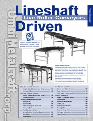
  • 1. (989) 358-7000 LineshaftDrivenLive RollerConveyors - 169 - Driven Live Roller Conveyors Lineshaft LineshaftDrivenLive RollerConveyors 24 Hour Shipment available on specific sizes. Consult a sales engineer for further information. General Operating Principle: General operation of the Lineshaft Driven Live Roller Conveyor is achieved through a drive shaft that spans the full length of the conveyor and transmits power to the rollers via a drive spool and belt. When back pressure is applied to the conveyed product, the spools driving the rollers will slip on the shaft, allowing the product to accumulate with a minimum amount of back pressure. Applications include transportation, minimum pressure accumulation, zero pressure accumulation and sortation. This conveyor offers quiet operation and easy maintenance. 3/8 in. dia. Lineshaft Conveyor Straight Slaved Sections and Drives ................ 170 Curves and Spurs ................................................. 172 1.9 in. dia. Lineshaft Conveyor Straight Slaved Sections and Drives ................ 174 Curves and Spurs ................................................. 176 Lineshaft Conveyor Belt Transfers Standard 90° ........................................................... 178 Reversing 90° ......................................................... 179 Bi-Directional (with drive unit) ........................... 180 Dual Lane Belt ....................................................... 181 Lineshaft Conveyor Options Spring Assisted Lineshaft Gate ......................... 182 Herringbone ........................................................... 183 Slaved Merge .......................................................... 183 Zero Pressure Lineshaft Driven Live Roller Conveyor ............................... 184 Dual Shaft ............................................................... 185 High Speed Pusher Device ................................. 185 Lineshaft Accessories Power & Crossover Device ................................. 186 Blade Stops ............................................................ 186 Pneumatic Roller Brake ....................................... 188 Traffic Cop .............................................................. 188 Bolt-Up Inline Diverter ......................................... 189 Turning Wheel ........................................................ 189 External Jump Chain ............................................ 190 Conveyor Accessories ......................................... 190 Special Options..................................................... 189
  • 2. (989) 358-7000 LineshaftDrivenLive RollerConveyors - 170 - Lineshaft Driven Live Roller Conveyor 1 3/8 in. dia. x 16 ga. Rollers The Lineshaft Driven Live Roller Conveyor is a unique concept in powered conveyors. It has the capability of accumulating products with minimum back pressure. Typical characteristics include quiet operation and easy maintenance. Standard Specifications: Frame - 5 1/2 in. deep x 1 1/2 in. flange x 12 ga. galvanized steel formed channel frames with bolt on end couplers. Between Frame Widths - 13 through 28 in full one inch increments. Rollers - 1 3/8 in. dia. x 16 ga. galvanized rollers with 5/16 in. hex axle and grease packed, semi-precision ball bearings. Rollers spaced on 1 1/2 in. centers. 1 3/8 in. dia. x 18 ga. galvanized rollers are available at speeds less than 60 FPM. Floor Supports - Adjustable 36 in. to 48 in. from floor to top of rollers. Drive Shaft - 1 in. dia. steel shaft full length of conveyor. Delrin chain coupling at bed joints. Drive Spools - 2 in. dia. Delrin spool held in place on shaft by “snap on” retaining clips. One drive spool drives two rollers. Drive Belts - 3/16 in. dia. urethane belts from drive spools to rollers. Spool Guard - Encloses underside of drive shaft, spools and drive belts for full length of conveyor. Bearings - Sealed, self-aligning, pre-lubricated ball bearings support drive shaft. Drive Section - Reducer and motor are mounted underneath conveyor. Note: Motor extends beyond frame of conveyor if between frame width is less than 20 inches. Side mounted drive sections are also available. Speed Reduction - “C” face speed reducer. No. 50 chain from reducer to drive shaft. Motor - 1/2 HP - 230/460V - 3 Phase - 60 Hz - totally enclosed, fan cooled - 1750 RPM. Conveying Speed - Constant 60 FPM. Load Capacities: - Max. load per powered roller = 10 lbs.* - Max. driven length with single drive at center = 70 ft. - Max. driven length per 1/4 HP = 10 ft. - Do not exceed a 75 lb. total product load without consulting an Omni Metalcraft Corp. Sales Engineer. * Will be less if product has uneven or soft bottom. sssss Minimum Back Pressure Accumulation sssss 16 Between Frame Widths sssss Single Drive Powers Straight Sections, Curves and Spurs sssss Semi-Precision Bearings for Longer Life and Noise Reduction sssss Reversible sssss Safe sssss Quiet ).sbl(thgieW evirD noitceS ).tf( evirD noitceS ).tf( ).tf(snoitceSdevalS neewteB emarF htdiW '3 '01 '1 '2 '3 '4 '5 '6 '7 '8 '9 '01 "31 "41 "51 "61 741 051 451 751 343 253 163 073 23 33 43 53 65 75 95 16 97 28 48 78 201 601 901 311 821 331 731 141 251 751 261 761 571 181 781 391 102 802 512 222 522 232 042 842 842 752 562 472 "71 "81 "91 "02 061 361 661 961 973 883 793 604 63 73 83 93 36 56 76 86 09 29 59 79 611 021 321 721 641 051 551 951 271 871 381 881 991 502 112 712 922 632 242 942 552 362 172 872 282 092 992 703 "12 "22 "32 "42 371 671 971 281 514 424 334 244 04 14 34 44 07 27 47 67 001 301 501 801 031 331 731 041 361 861 271 671 391 891 302 902 322 922 532 142 652 362 072 772 682 492 103 903 613 423 333 143 "52 "62 "72 "82 581 881 291 591 154 064 964 874 54 64 74 84 87 97 18 38 111 311 611 911 441 741 151 451 181 581 981 491 412 912 422 922 742 352 952 562 482 192 792 403 713 423 233 043 053 853 763 573 FLOW Retaining Clip Drive Shaft Drive Belt Tread Roller Drive Spool
  • 3. (989) 358-7000 LineshaftDrivenLive RollerConveyors - 171 - Optional Equipment: Keyed Spools - Spools are keyed and fit into a keyseat on the drive shaft. Instead of slipping on the shaft, spools provide positive drive. NOTE: Keyed spool conveyor sections cannot exceed 4 ft. long. Speed-Up Spools - Larger diameter spools that increase speed 1.3 times the original speed. Pneumatic Roller Brake - Air operated conveyor accessory that stops rollers in 2 ft. or 3 ft. zones. See page 188 for details. Blade Stops - Pneumatically or manually operated blade that pops up between rollers in order to accumulate product. See page 186 and 187 for details. Timing Belt Drive - Used as an option to chain drive, allowing for quieter operation. Timing belt drive is required at a speed of 120 FPM. Roller Centers - 3 in., 4 1/2 in. and 6 in. roller centers are also available. Power Crossover - 1 ft. long section that switches drive shaft from one side of the conveyor to the other. Timing belt and chain driven models available. See page 186 for details. Can also be used to increase speeds. External Jump Chain - 3 ft. long section with a jump chain that transmits power from one conveyor line to a parallel conveyor line. One drive can power two parallel lines. Chain driven and timing belt driven models available. See page 190 for details. Can also be used to increase speeds. Conveying Speed - Constant and variable speeds from 25 to 120 FPM. AC or DC variable speed controllers available. Urethane BeltTransfer - 3 ft.long section has an air operated lifting device that raises urethane transfer belts above the roller surface to transfer product off @ 90°. See pages 178,179,180 and 181 for details. Spring Assisted Gate Section - 6 ft. section consisting of 2 ft. fixed section and 4 ft. gate section. See page 182 for details. Guard Rails - 1 1/2 in. wide x 2 in. high x 12 ga. galvanized steel formed angle. One or both sides. Note: If product contacts guard rails, product flow may be affected. Floor Supports - Available in higher or lower height adjustments. Ceiling Hangers - 5/8 in. dia. x 10 ft. long threaded rod with mounting hardware. Other Rollers - 1 3/8 in. dia. x 18 ga. or 1 3/8 in. dia. x 3/16 in. wall tubing. Closed style non-precision bearings also available. Motors - Single phase, drip proof, DC motors, inverter duty motors available through 2 HP. Electrical Controls - Start-Stop push button stations, reversing drum switch, one direction and reversible magnetic starters. Side Mount Drive - Allows minimum top of roller height of 10 3/4 inches. Note: Motor is vertical. OVERALL LENGTH 1' TO 10' SLAVED SECTION(S) 2' TO 10' DRIVE SECTION 21 1/4" MIN. T.O.R. 18 7/16" BETWEEN FRAME WIDTH 3/16" 5 1/2" DRIVE BELT RETAININGCLIP 2" 1 1/2" SPOOL GUARD DRIVE SPOOL 4 7/8" 2 3/4" Model Number: Slaved Section LSSS1.4 x 16 - __ - 1.5 - __ Length (1 ft. to 10 ft.) Roller Description Between Frame Width (13 in. to 28 in.) Roller Spacing Model Number: Drive Section LSDS1.4 x 16 - __ - 1.5 - __ - F __ - __ - CD - H.P. (1/3 to 2) Speed (25 to 120 FPM) Speed Type (F) = Fixed Speed (V) = Variable Speed Length (2 ft. to 10 ft.) Roller Description Between Frame Width (13 in. to 28 in.) Roller Spacing CD = Chain Driven TB = Timing Belt Driven SM = Side Mount Drive Leaveblankifdriveis underhung 14 1/4" SPOOLGUARD
  • 4. (989) 358-7000 LineshaftDrivenLive RollerConveyors - 172 - Lineshaft Driven Curve and Spur Conveyor Curves - 1 in. to 1 1/2 in. dia. x 18 ga. Tapered Rollers Spurs - 1 3/8 in. dia. x 16 ga. Straight Rollers sssss 16 Between Frame Widths sssss Curves are Transportation Conveyors Only sssss Slave Driven from Straight Section or Self Powered sssss 30°,45°,60° and 90° Curves; 30° and 45° Spurs sssss Tapered Rollers on Curves Lineshaft Curves and Spurs are slave driven from lineshaft straight sections or powered by their own drive unit. Curves allow for turns in the product line, whereas spurs are used when product lines converge or diverge. Note: 30° curves have 1 ft. tangent sections at each end. 45° CURVE 90° CURVE DRIVE SHAFT U-JOINT SHAFT COUPLING 36"INSIDE RADIUS 45° 36"INSIDE RADIUS SHAFT COUPLING 90° U-JOINT DRIVE SHAFT BETWEEN FRAME WIDTH1 1/2" DRIVEBELT 3/16" 5 1/2" DRIVESPOOL SPOOLGUARD 2" 2 3/4" Model Number: LSSC1.4 x 18 - __ - 3 - __ - T (T) Tapered Roller Degree of Curve (30°, 45°, 60° or 90°) Roller Description Between Frame Width (13 in. to 28 in.) Equivalent Roller Spacing evruC°09 ROYEVNOC ).sbl(THGIEWneewteB emarF htdiW forebmuN srelloR evruCno relloR @sretneC enilretneC °03 °54 °06 °09 "31 "41 "51 "61 "71 23 derepaT srelloR "680.2 "111.2 "531.2 "061.2 "481.2 15 35 55 65 85 39 59 79 99 101 901 311 511 811 121 471 971 381 781 191 "81 "91 "02 "12 "22 "902.2 "432.2 "852.2 "382.2 "703.2 95 06 16 26 36 301 501 701 011 211 321 621 821 031 331 591 991 302 702 112 "32 "42 "52 "62 "72 "82 "233.2 "653.2 "183.2 "504.2 "034.2 "454.2 671 971 381 681 981 291 501 701 901 111 311 611 041 341 641 841 151 451 822 232 732 142 542 942
  • 5. (989) 358-7000 LineshaftDrivenLive RollerConveyors - 173 - 45° SPUR LEFT HAND RIGHT HAND Model Number: LSS__ - 1.4 x 16 - __ - 1.5 - __ Between Frame Width (13 in. to 28 in.) Roller Description (slaved from this end) R = Right Hand L = Left Hand Roller Spacing Angle of Spur (30° or 45°) Optional Equipment: Drive - Drive units can be mounted to curves and spurs to give them power without being slave driven. Guard Rails - 1 1/2 in. wide x 2 in. high x 12 ga. galvanized steel formed angle. One or both sides. Note: If product contacts guard rails, product flow may be affected. Floor Supports - Available in higher or lower height adjustments. Ceiling Hangers - 5/8 in. dia. x 10 ft. long threaded rod with mounting hardware. Wheel Diverter - Pneumatically controlled device that automatically diverts product from main line onto a 30° spur. See page 189 for more details. Traffic Cop - Controls product flow where two lines converge eliminating product collisions. Only one line is open at a given time. See page 188 for more details. TurningWheel - Used on converging lines to insure proper product orientation when product is transferred onto a main line. See page 189 for more details. Slaved Merge - Integral spur and straight section used in applications where products must merge with another conveying line. Both sections are slaved off a common drive. See page 183 for more details. TrueTapered Roller Curve - True tapered roller curve available. Will require special radius or special rollers. Standard Specifications: Frame - 5 1/2 in. deep x 1 1/2 in. flange x 12 ga. galvanized steel formed channel frames with bolt on end couplers. Note: Outside rail of curve has“triple-punched”hex holes to allow skewing of rollers which affects product tracking. Curve rollers do not represent a true taper. Between FrameWidths - 13 through 28 in full one inch increments. Curve Rollers - 1 1/2 in. dia. tapered to 1 in. dia. x 18 ga. zinc plated rollers. Grease packed, semi-precision ball bearings. Spur Rollers - 1 3/8 in. dia. x 16 ga. galvanized rollers on 1 1/2 in. centers. Grease packed ball bearings. Floor Supports - Adjustable 36 in. to 48 in. from floor to top of rollers. Slave Driven - Curves or spurs are slave driven from the drive shaft of a lineshaft straight section. Shafts are coupled by a Delrin chain coupling at bed joints. Drive Shaft - 1 in. dia. steel shaft with universal joints as necessary. Drive Spools - 2 in. dia. Delrin spool held in place on shaft by “snap on” retaining clips. One drive spool drives two rollers. Drive Belts - 3/16 in. dia. high tension urethane belt from drive spools to rollers. Spool Guard - Encloses underside of drive shaft, spools and drive belts. Bearings - Sealed, pre-lubricated, self-aligning ball bearings on drive shaft. Load Capacities - Same roller capacity as lineshaft 1.4 straight sections. DRIVE SHAFT* “B” “C” SHAFT COUPLING “A” 45° ROYEVNOCRUPS°03 ROYEVNOCRUPS°54 neewteB emarF htdiW ”A“ ).ni( ”B“ ).ni( ”C“ ).ni( .tW ).sbl( ”A“ ).ni( ”B“ ).ni( ”C“ ).ni( .tW ).sbl( "31 "41 "51 "61 "71 61/3103 4/373 4/373 4/373 61/1144 63 84 84 84 84 21 12 12 81 51 74 37 67 77 87 8/182 8/182 8/182 8/323 8/323 63 63 63 63 63 12 12 12 81 81 65 95 26 26 46 "81 "91 "02 "12 "22 61/1144 61/1144 61/1144 2/135 2/135 84 84 84 06 06 51 21 21 12 81 08 08 28 711 811 8/323 61/963 61/963 61/993 61/3104 63 63 63 63 63 81 51 51 51 21 76 66 86 17 07 "32 "42 "52 "62 "72 "82 2/135 61/985 61/985 61/985 61/985 61/376 06 06 06 06 06 27 81 51 51 21 21 12 021 121 421 421 621 761 61/3104 61/3104 61/154 61/154 61/154 61/594 63 63 84 84 84 84 21 21 12 12 12 81 27 47 311 511 911 811 * Dark shaft indicates positive drive spools Note: Minimum recommended product length to converge or diverge product is 12".
  • 6. (989) 358-7000 LineshaftDrivenLive RollerConveyors - 174 - Lineshaft Driven Live Roller Conveyor 1.9 in. dia. x 16 ga. Rollers sssss Minimum Back Pressure Accumulation sssss 27 Between Frame Widths sssss Reversible sssss Single Drive Powers Straight Sections, Curves and Spurs sssss Safe sssss Quiet Standard Specifications: Frame - 5 1/2 in. deep x 1 1/2 in. flange x 12 ga. galvanized steel formed channel frames with bolt on end couplers. Between FrameWidths - 13 through 39 in full one inch increments. Rollers - 1.9 in. dia. x 16 ga. galvanized rollers with 7/16 in. hex axle and grease packed ball bearings. Rollers spaced on 3 in. centers. Drive Shaft - 1 in.dia.steel shaft full length of conveyor. Delrin chain coupling at bed joints. Drive Spools - 2 in. dia. Delrin spool held in place on shaft by “snap-on” retaining clips. Drive Belts - 3/16 in. dia. urethane belts from drive spools to rollers. Spool Guard - Encloses underside of drive shaft, spools and drive belts for full length of conveyor. Bearings - Sealed, self-aligning, pre-lubricated ball bearings support drive shaft. Drive Section - Reducer and motor mounted underneath conveyor. Note: Motor extends beyond frame of conveyor if between frame width is less than 20 in. Speed Reduction - “C” face speed reducer. No. 50 chain from reducer to drive shaft. Motor - 1/2 HP - 230/460V - 3 Phase - 60 Hz - totally enclosed, fan cooled - 1750 RPM. Conveying Speed - Constant 60 FPM. Load Capacities: - Max. load per powered roller = 15 lbs.* - Max. driven length with single drive at center = 120 ft. - Max. driven length per 1/4 HP = 20 ft. - Do not exceed a 75 lb. total product load without consulting an Omni Metalcraft Corp.Sales Engineer. * Will be less if product has uneven or soft bottom. ).sbl(thgieW evirD noitceS ).tf( evirD noitceS ).tf( ).tf(snoitceSdevalS neewteB emarF *htdiW '3 '01 '1 '2 '3 '4 '5 '6 '7 '8 '9 '01 "31 "41 "51 "61 "71 "81 "91 "02 "12 431 731 931 241 541 741 051 251 551 382 292 792 603 513 023 923 433 343 92 03 13 23 33 43 53 53 63 05 25 35 55 75 85 95 06 26 17 37 57 77 08 18 48 58 88 19 59 79 001 301 501 901 111 411 411 911 121 521 031 231 731 931 341 531 041 341 841 351 651 161 461 961 651 261 561 171 771 081 681 981 591 971 681 981 691 302 702 412 712 422 991 702 112 912 722 132 832 242 052 022 922 332 242 052 452 362 762 672 "22 "32 "42 "52 "62 "72 "82 "92 "03 751 061 461 661 861 171 471 671 871 843 753 663 173 673 583 493 993 404 73 83 93 04 04 14 34 34 44 36 56 76 86 96 17 37 47 57 09 29 59 69 89 001 301 401 601 611 911 321 521 621 031 331 531 731 641 051 451 751 951 361 861 071 271 271 771 281 581 881 391 891 102 402 891 402 012 312 612 222 822 132 532 822 532 242 542 942 652 362 662 072 452 262 072 472 872 582 392 792 103 082 982 792 203 603 513 323 823 233 "13 "23 "33 "43 "53 "63 "73 "83 "93 181 381 681 881 191 391 691 891 202 314 814 724 234 144 644 554 064 964 54 54 74 74 84 94 05 15 25 77 87 08 18 28 38 58 68 88 901 011 311 411 711 811 121 221 521 041 241 641 841 151 351 651 851 261 771 081 481 681 091 391 791 991 402 902 112 712 912 522 722 232 532 042 142 442 052 352 952 262 862 172 772 772 182 882 192 892 203 903 213 913 903 313 123 523 233 633 443 843 653 143 543 453 853 763 173 083 483 393 The Lineshaft Driven Live Roller Conveyor is a unique concept in powered conveyors. It has the capability of accumulating products with minimum back pressure. Typical characteristics include quiet operation and easy maintenance.
  • 7. (989) 358-7000 LineshaftDrivenLive RollerConveyors - 175 - OVERALL LENGTH 1' TO 10' SLAVED SECTION(S) 2' TO 10' DRIVE SECTION 14 1/4" 21 1/4" MIN. T.O.R. 18 7/16" 1/4" 5 1/2" DRIVE BELT RETAININGCLIP 2" 1 1/2" SPOOL GUARD DRIVESPOOL 4 7/8" 2 3/4" Optional Equipment: Keyed Spools - Spools are keyed and fit into a keyseat on the drive shaft. Instead of slipping on the shaft, spools provide positive drive. NOTE: Keyed spool conveyor sections cannot exceed 4 ft. long. Speed-Up Spools - Larger diameter spools that increase speed 1.3 times the original speed. Pneumatic Roller Brake - Air operated conveyor accessory that stops rollers in 2 ft. or 3 ft. zones. See page 188 for details. Blade Stops - Pneumatically or manually operated blade that pops up between rollers in order to accumulate product. See page 186 and 187 for details. Timing Belt Drive - Used as an option to chain drive, allowing for quieter operation. Timing belt drive is required at speeds from 120 to 180 FPM. Roller Centers - 3 in., 4 in., 6 in. and 8 in. roller centers are also available. Power Crossover - 1 ft. long section that switches drive shaft from one side of the conveyor to the other. Timing belt and chain driven models available. See page 186 for details. Can also be used to increase speeds. External Jump Chain - 3 ft. long section with a jump chain that transmits power from one conveyor line to a parallel conveyor line. One drive can power two parallel lines. Chain driven and timing belt driven models available. See page 190 for details. Can also be used to increase speeds. Floor Supports - Available in higher or lower height adjustments. Conveying Speed - Constant and variable speeds from 25 to 180 FPM. AC or DC variable speed controllers available. Urethane BeltTransfer - 3 ft.long section has an air operated lifting device that raises urethane transfer belts above the roller surface to transfer product off @ 90°. See pages 178, 179, 180 and 181 for details. Spring Assisted Gate Section - 6 ft. section consisting of 2 ft. fixed section and 4 ft. gate section. See page 182 for details. Guard Rails - 1 1/2 in. wide x 2 in. high x 12 ga. galvanized steel formed angle. One or both sides. Note: If product contacts guard rails, product flow may be affected. Ceiling Hangers - 5/8 in. dia. x 10 ft. long threaded rod with mounting hardware. Other Rollers - 1.9 in. dia. x 13 ga. or 1.9 in. dia. x .145 wall, semi-precision and precision bearings available for extended life and noise reduction. Motors - Single phase, drip proof, DC motors, inverter duty motors available through 2 HP. Electrical Controls - Start-Stop push button stations, reversing drum switch, one direction and reversible magnetic starters. Side Mount Drive - Allows minimum top of roller height of 10 3/4 inches. Note: Motor is vertical. SPOOLGUARD Model Number: Slaved Section LSSS1.9 x 16 - __ - - __ Length (1 ft. to 10 ft.) Roller Description Between Frame Width (13 in. to 39 in.) Roller Spacing Model Number: Drive Section LSDS1.9 x 16 - __ - - __ - F __ - __ - CD - H.P. (1/3 to 2) Speed (25 to 180 FPM) Speed Type (F ) = Fixed Speed (V) = Variable Speed Length (2 ft. to 10 ft.) Roller Description Between Frame Width (13 in. to 39 in.) Roller Spacing CD = Chain Driven TB = Timing Belt Driven SM = Side Mount Drive Leave blank if drive is underhung BETWEENFRAMEWIDTH
  • 8. (989) 358-7000 LineshaftDrivenLive RollerConveyors - 176 - Lineshaft Driven Curve and Spur Conveyor Curves - 1 11/16 in. to 2 1/2 in. dia. x 14 ga. Tapered Rollers Spurs - 1.9 in. dia. x 16 ga. Straight Rollers sssss 27 Between Frame Widths sssss Curves are Transportation Conveyor Only sssss Slave Driven from Straight Section or Self Powered sssss 30°, 45°, 60° and 90° Curves; 30° and 45° Spurs sssss Tapered Rollers on Curves Lineshaft Curves and Spurs are slave driven from lineshaft straight sections and are powered by their own drive unit. Curves allow for turns in the product line, whereas spurs are used when product lines converge or diverge. 45° CURVE 90° CURVE DRIVE SHAFT U-JOINT SHAFT COUPLING 36" INSIDE RADIUS 45° 36" INSIDE RADIUS SHAFT COUPLING 90° U-JOINT Note: 30° curves have 1 ft. tangent sections at each end. DRIVE SHAFT BETWEEN FRAME WIDTH1 1/2" DRIVE BELT 1/4" 5 1/2" DRIVE SPOOL SPOOL GUARD 2" 2 3/4" Model Number: LSSC1.9 x 16 - __ - 3 - __ - T T= Tapered Roller Degree of Curve (30°, 45°, 60° or 90°) Roller Description Between Frame Width (13 in. to 39 in.) Equivalent Roller Spacing evruC°09 RELLORDEREPAT neewteB emarF htdiW srelloR °09reP evruC relloR @sretneC enilretneC ).sbL(thgieW °03 °54 °06 °09 "31 "41 "51 "61 "71 42 derepaT srelloR "187.2 "418.2 "748.2 "088.2 "319.2 621 031 231 631 041 98 29 39 69 99 121 521 721 131 631 491 991 302 802 412 "81 "91 "02 "12 "22 "549.2 "879.2 "110.3 "340.3 "670.3 241 641 841 251 551 101 401 501 801 011 831 241 441 841 151 812 322 722 332 632 "32 "42 "52 "62 "72 "901.3 "241.3 "471.3 "702.3 "042.3 851 261 461 761 071 311 611 711 911 221 551 951 161 461 861 242 842 152 452 062 "82 "92 "03 "13 "23 "272.3 "503.3 "833.3 "173.3 "304.3 471 771 971 381 581 521 721 821 131 331 271 471 771 181 381 662 962 372 972 282 "33 "43 "53 "63 "73 "634.3 "964.3 "205.3 "435.3 "765.3 281 581 981 191 591 631 831 041 241 541 781 981 391 691 002 882 192 792 003 603 "83 "93 "006.3 "236.3 791 102 741 051 202 602 903 513
  • 9. (989) 358-7000 LineshaftDrivenLive RollerConveyors - 177 - 45° SPUR LEFT HAND RIGHT HAND Optional Equipment: Drive - Drive units can be mounted to curves and spurs rather than being slave driven. Guard Rails - 1 1/2 in. wide x 2 in. high 12 ga. galvanized steel formed angle. One or both sides. Note: If product contacts guard rails, product flow may be affected. Floor Supports - Available in higher or lower height adjustments. Ceiling Hangers - 5/8 in. dia. x 10 ft. long threaded rod with mounting hardware. Wheel Diverter - Pneumatically controlled device that automatically diverts product from main line onto a 30° spur. See page 189 for more details. Traffic Cop - Controls product flow where two lines converge eliminating product collisions. Only one line is open at a given time. See page 188 for more details. TurningWheel - Used on converging lines to insure proper product orientation when product is transferred onto a main line. See page 189 for more details. Slaved Merge - Integral spur and straight section used in applications where products must merge with another conveying line. Both sections are slaved off a common drive. See page 183 for more details. Standard Specifications: Frame - 5 1/2 in. deep x 1 1/2 in. flange x 12 ga. galvanized steel formed channel frames with bolt on end couplers. Note: Outside rail of curve has “triple-punched”hex holes to allow skewing of rollers which affects product tracking. Curve rollers do not represent a true taper. Between FrameWidths - 13 through 39 in full one inch increments. Curve Rollers - 2 1/2 in. dia. tapered to 1 11/16 in. dia. x 14 ga. zinc plated rollers. Grease-packed ball bearings. Spur Rollers - 1.9 in. dia. x 16 ga. galvanized rollers with 7/16 hex axle on 3 in. centers. Grease-packed ball bearings. Floor Supports - Adjustable 36 in. to 48 in. from floor to top of rollers. Slave Driven - Curves or spurs are slave driven from the drive shaft of a lineshaft straight section. Shafts are coupled by a Delrin chain coupling at bed joints. Drive Shaft - 1 in. dia. steel shaft with universal joints as necessary. Drive Spools - 2 in. dia. Delrin spool held in place on shaft by “snap on” retaining clips. Drive Belts - 3/16 in. dia. high tension urethane belt from drive spools to rollers. Spool Guard - Encloses underside of drive shaft, spools and drive belts. Bearings - Sealed, pre-lubricated, self-aligning ball bearings on drive shaft. Load Capacities - Same roller capacity as lineshaft 1.9 straight sections. DRIVE SHAFT* “B” “C” SHAFT COUPLING “A” 45° * Dark shaft indicates positive drive spools Model Number: LSS__ - 1.9 x 16 - __ - 3 - __ Angle of Spur (30° or 45°) Roller Spacing Between Frame Width (13 in. to 39 in.) Roller Description R = Right Hand L = Left Hand Note: Minimum product length recommended to converge or diverge product is 12". RUPS°03 RUPS°54 neewteB emarF htdiW ”A“ ).ni( ”B“ ).ni( ”C“ ).ni( .tW ).sbl( ”A“ ).ni( ”B“ ).ni( ”C“ ).ni( .tW ).sbl( "31 "41 "51 "61 "71 61/3103 4/373 4/373 4/373 61/1144 63 84 84 84 84 21 12 12 81 51 23 74 94 84 84 8/182 8/182 8/182 8/323 8/323 63 63 63 63 63 12 12 12 81 81 73 83 04 93 04 "81 "91 "02 "12 "22 61/1144 61/1144 61/1144 2/135 2/135 84 84 84 06 06 51 21 21 12 81 94 94 05 07 96 8/323 61/963 61/963 61/993 61/3104 63 63 63 63 63 81 51 51 51 21 24 04 24 44 14 "32 "42 "52 "62 "72 2/135 61/985 61/985 61/985 61/985 06 06 06 06 06 81 51 51 21 21 17 07 27 17 37 61/3104 61/3104 61/154 61/154 61/154 63 63 84 84 84 21 21 12 12 12 34 54 56 76 07 "82 "92 "03 "13 "23 61/376 61/376 61/376 8/327 8/327 27 27 27 27 27 12 81 81 51 51 69 69 89 79 99 61/594 61/594 61/594 61/935 61/935 84 84 84 84 84 81 81 81 51 51 76 96 27 86 17 "33 "43 "53 "63 "73 8/327 8/327 61/118 61/118 61/118 27 27 48 48 48 21 21 12 81 81 89 001 721 621 921 61/935 8/775 8/775 8/775 61/126 84 84 84 84 06 51 21 21 21 12 37 96 27 47 001 "83 "93 2/148 2/148 48 48 51 51 821 031 61/126 61/126 06 06 12 12 301 601
  • 10. (989) 358-7000 LineshaftDrivenLive RollerConveyors - 178 - Urethane Belt Transfer Device - Standard Flow 1 3/8 in. or 1.9 in. dia. Rollers Transfer Belt Height - Factory assembled to raise 3/8 in.above conveying surface, but adjustable to 3/4 in. Slave Driven - Unit is slave driven from the drive shaft of a lineshaft straight section. Shafts are coupled by a Delrin chain coupling at bed joints. Air Bag - No-maintenance air bag provides approximately 100 to 600 lbs. force from 45 to 100 PSI respectively. Air Requirements - 45 PSI to 100 PSI. Pressure should be regulated to minimum PSI required to actuate device at installation. Valve - Single solenoid 4-way valve. 1/4 in. NPT valve ports. Requires maintained electrical signal of 115V - 1 Phase - 60 Hz Filter/Regulator - Supplied for main air supply line - 3/8 in. NPT port. Options: • Drive Unit • Timing Belt Jump Chain • 5th Belt on Center • End Guard Kit • Optional Belt Centers • Blade Stop Installed • Roller Brake Installed The Belt Transfer Device is slaved from other lineshaft sections. Transfer belts are raised pneumatically above conveying surface to transfer product at 90° onto another conveyor line. NOTE: This is a slaved unit. Speed and direction of the product being transferred is dictated by the speed and direction of the shaft from which it is slaved. Minimum recommended product width = 15". If product is less than 15" wide or not long enough to contact the four transfer belts, consult an Omni sales engineer for pricing on extended belts or special belt centers. Standard Specifications: Load Capacity - Maximum package weight: 75 lbs. Frame - 11 in. deep x 1 1/2 in. flange x 12 ga. galvanized steel formed channel frames with bolt-on end couplers. Between FrameWidths - 13 through 28 in full one inch increments for 1 3/8 in.roller. 13 through 39 in full one inch increments for 1.9 in.roller. Rollers - 1 3/8 in. dia. galvanized rollers with 5/16 in. hex axle on 1 1/2 in. centers or 1.9 in. dia. x 16 ga. galvanized rollers with 7/16 hex axle on 3 in. centers. Both have grease-packed ball bearings. Transfer Belts - Four powered 3/8 in.dia.urethane belts are pneumatically lifted above roller surface to transfer product off @ 90°. See chart for belt centers. Jump Chain - Transmits power from power shaft to idler shaft. Available in chain driven & timing belt driven models. Transfer Belt Centers - Model Number: LSSB____ - __ - CD - STB CD = Chain Driven TB = Timing Belt Driven Between Frame Width (13 in. to 39 in.) for 1.9 (13 in. to 28 in.) for 1 3/8 Roller Description (1.4 x 16) 1 3/8 in. dia. x 16 ga. (1.9 x 16) 1.9 in. dia. x 16 ga. Standard Transfer Belts – 36" B A A B C A FLOW BETWEENFRAMEWIDTH FLOW NOTE: Min. Top of Roller = 11 1/4 in. Shaft Rotation EndView D 11" 1 7/8" (Typ.) SDRADNATSREFSNARTTLEB relloR retemaiD A B C D 8/31 8/57 2/14 2/11 61/3 9.1 2/101 2/13 3 4/1
  • 11. (989) 358-7000 LineshaftDrivenLive RollerConveyors - 179 - ZeroPressureLineshaft DrivenLiveRollerConveyors GravityConveyorsBeltConveyors Urethane Belt Transfer Device - Reverse Flow 1 3/8 in. or 1.9 in. dia. Rollers Standard Specifications: Load Capacity - Maximum package weight: 75 lbs. Frame - 11 in. deep x 1 1/2 in. flange x 12 ga. galvanized steel formed channel frames with bolt on end couplers. Between FrameWidths - 13 through 28 in full one inch increments for 1 3/8 in.roller. 13 through 39 in full one inch increments for 1.9 in.roller. Rollers - 1 3/8 in. dia. galvanized rollers with 5/16 in. hex. axle on 1 1/2 in. centers or 1.9 in. dia. x 16 ga. galvanized rollers with 7/16 hex. axle on 3 in. centers. Both have grease-packed ball bearings. Transfer Belts - Four powered 3/8 in.dia.urethane belts are pneumatically lifted above roller surface. See chart for belt centers. Jump Chain - Transmits power from power shaft to idler shaft. Available in chain driven and timing belt driven models. Transfer Belt Centers - Transfer Belt Height - Factory assembled to raise 3/8 in. above conveying surface, but adjustable to 3/4 in. Slave Driven - Unit is slave driven from the drive shaft of a lineshaft straight section. Shafts are coupled by a Delrin chain coupling at bed joints. Air Bag - No maintenance air bag provides approximately 100 to 600 lbs. force from 45 to 100 PSI respectively. Air Requirements - 45 PSI to 100 PSI. Pressure should be regulated to minimum PSI required to actuate device at installation. Valve - Single solenoid 4-way valve. 1/4 in. NPT valve ports. Requires maintained electrical signal of 115V - 1 Ph. - 60 Hz. Filter/Regulator - Supplied for main air supply line - 3/8 in. NPT port. Options: • Drive Unit • Timing Belt Jump Chain • 5th Belt on Center • End Guard Kit • Optional Belt Centers • Blade Stop Installed • Roller Brake Installed SectionA-A – Shaft Rotation Model Number: LSSB____ - __ - CD - RTB CD = Chain Driven TB = Timing Belt Driven Between Frame Width (13 in. to 28 in.) for 1 3/8 (13 in. to 39 in.) for 1.9 Roller Description (1.4 x 16) 1 3/8 in. dia. x 16 ga. (1.9 x 16) 1.9 in. dia. x 16 ga. Reverse Transfer Belts D 11" A A 36" A BB BETWEENFRAMEWIDTH FLOW SDRADNATSREFSNARTTLEB relloR retemaiD A B C D 8/31 8/57 2/14 2/11 61/3 9.1 2/101 2/13 3 4/1 FLOW 1 7/8" (Typ.) NOTE: This is a slaved unit. Speed and direction of the product being transferred is dictated by the speed and direction of the shaft from which it is slaved. Minimum recommended product width = 15". If product is less than 15" wide or not long enough to contact the four transfer belts, consult an Omni sales engineer for pricing on extended belts or special belt centers. NOTE: Min. Top of Roller = 11 1/4 in. The Belt Transfer Device is slaved from other lineshaft sections. Transfer belts are raised pneumatically above conveying surface to transfer product at 90° onto another conveyor line. Product transfers opposite that of device on page 178 even though shaft rotation is the same. C
  • 12. (989) 358-7000 LineshaftDrivenLive RollerConveyors - 180 - Urethane Belt Transfer Device - Bi-Directional 1 3/8 in. or 1.9 in. dia. Rollers SectionA-A This Belt Transfer Device’s tread rollers are slaved from other lineshaft sections. Transfer belts are independently powered by a separate drive and are pneumatically raised above conveying surface to transfer products at 90°, in either direction, onto another conveyor line. Speed Reduction - “C” face speed reducer. No. 50 chain from reducer to drive shaft. Filter/Regulator - Supplied for main air supply line - 3/8 in. NPT port. Motor - 1/2 HP - 230/460V - 3 Phase - 60 Hz - totally enclosed, fan cooled - 1750 RPM. Transfer Belt Drive Sheaves - Positively driven independent sheaves power the transfer belts. Air Bag - No-maintenance air bag provides approximately 270 to 600 lbs. force from 45 to 100 PSI respectively. Air Requirements - 45 PSI to 100 PSI. Pressure should be regulated to minimum PSI required to actuate device at installation. Valve - Single solenoid 4-way valve. 1/4 in. NPT valve ports. Requires maintained electrical signal of 115V - 1 Phase - 60 Hz. Options: • Drive Unit • Timing Belt Jump Chain • 5th Belt on Center • End Guard Kit • Optional Belt Centers • Blade Stop Installed NOTE: Transfer belts are driven independent of lineshaft. Lineshaft is slaved from adjoining section to power rollers. Minimum recommended product width = 15". Bi-directional transfers are not available at widths less than 16". If product is less than 15" wide or not long enough to contact the four transfer belts, consult an Omni sales engineer for pricing on extended belts or special belt centers. B 36" B A A BETWEENFRAMEWIDTH FLOW FLOW C FLOW Standard Specifications: Load Capacity - Maximum package weight: 75 lbs. Frame - 11 in. deep x 1 1/2 in. flange x 12 ga. galvanized steel formed channel frames with bolt on end couplers. Between FrameWidths - 16 through 28 in full one inch increments for 1 3/8 in. roller. 16 through 39 in full one inch increments for 1.9 in. roller. Rollers - 1 3/8 in. dia. galvanized rollers with 5/16 in. hex. axle on 1 1/2 in. centers or 1.9 in. dia. x 16 ga. galvanized rollers with 7/16 hex. axle on 3 in. centers. Both have grease-packed ball bearings. Transfer Belts - Four powered 3/8 in.dia. urethane belts are pneumatically lifted above roller surface. See chart for belt centers. Transfer Belt Height - Factory assembled to raise 3/8 in.above conveying surface, but adjustable to 3/4 in. Slave Driven - Rollers are slave driven from the drive shaft of a lineshaft straight section. Shafts are coupled by a Delrin chain coupling at bed joints. Transfer Belt Centers - CD = Chain Driven TB = Timing Belt Driven Between Frame Width (16 in. to 28 in.) for 1 3/8 (16 in. to 39 in.) for 1.9 A SDRADNATSREFSNARTTLEB relloR retemaiD A B C D 8/31 8/57 2/14 2/11 61/3 9.1 2/101 2/13 3 4/1 Model Number: LSDB - __ - __ Roller Description (1.4 x 16) 1 3/8 in. dia. x 16 ga. (1.9 x 16) 1.9 in. dia. x 16 ga. D1 7/8" (Typ.) 11" 23 1/4" MIN. T.O.R.
  • 13. (989) 358-7000 LineshaftDrivenLive RollerConveyors - 181 - Urethane Belt Transfer Device - Dual Lane 1 3/8 in. or 1.9 in. dia. Rollers1 3/8 in. dia. x 18 ga. Rollers Standard Specifications: Load Capacity - Maximum package weight: 75 lbs. Frame - 11 in. deep x 1 1/2 in. flange x 12 ga. galvanized steel formed channel frames with bolt-on end couplers. Between FrameWidths - 13 through 28 in full one inch increments for 1 3/8 in. roller. 13 through 39 in full one inch increments for 1.9 in. roller. Between Lane Dimension - 5 through 15 in full one inch increments. Rollers - 1 3/8 in. dia. galvanized rollers with 5/16 in. hex. axle on 1 1/2 in. centers or 1.9 in. dia. x 16 ga. galvanized rollers with 7/16 hex. axle on 3 in. centers. Both have grease-packed ball bearings. Transfer Belts - Four powered 3/8 in.dia.urethane belts are pneumatically lifted above roller surface. See chart for belt centers. Jump Chain - Transmits power from one lane to the next lane. Available in chain driven and timing belt driven models. Transfer Belt Centers - Transfer Belt Height - Factory assembled to raise 3/8 in. above conveying surface, but adjustable to 3/4 in. Slave Driven - Unit is slave driven from the drive shaft of a lineshaft straight section. Shafts are coupled by a Delrin chain coupling at bed joints. Both lanes are powered by a common drive. Air Bag - No-maintenance air bag provides approximately 100 to 600 lbs.force from 45 to 100 PSI respectively. Air Requirements - 45 PSI to 100 PSI. Pressure should be regulated to minimum PSI required to actuate device at installation. Valve - Single solenoid 4-way valve. 1/4 in.NPT valve ports. Requires maintained electrical signal of 115V - 1 Phase - 60 Hz. Filter/Regulator - Supplied for main air supply line - 3/8 in. NPT port. Options: • Drive Unit • Roller Brake Installed • 5th Belt on Center • Timing Belt Jump Chain • Optional Belt Centers • End Guard Kit A Dual Lane Belt Transfer Device is slaved from other lineshaft sections. Transfer belts are pneumatically raised above the conveying surface to transfer product at 90° onto another parallel conveying line. SDRADNATSREFSNARTTLEB relloR retemaiD A B C D 8/31 8/57 2/14 2/11 61/3 9.1 2/101 2/13 3 4/1 OVERALLBETWEENFRAMEWIDTH BETWEENFRAMEWIDTH BETWEEN LANE DIMENSION MIN=5"/MAX=15" A 36" A BETWEENFRAMEWIDTH 1 1/2" NOTE: This is a slaved unit. Speed and direction of the product being transferred is dictated by the speed and direction of the shaft from which it is slaved. If product is not long enough to contact the four transfer belts, consult an Omni sales engineer for pricing on special belt centers. B B A C 12 1/2" BETWEEN FRAME WIDTH BETWEEN FRAME WIDTH BETWEEN LANES 5" MIN 15" MAX 11" 1 7/8"1 7/8" 12 3/4" MINIMUM TOPOFROLLER SECTION A-A STANDARD FLOW TRANSFER(STB) SECTION A-A REVERSE FLOW TRANSFER (RTB) Model Number: LSBB - __ - - __ - __ Transfer Type RTB = Reverse Flow Belt Transfer STB = Standard Flow Belt Transfer CD = Chain Driven TB = Timing Belt Driven Roller Description (1.4 x 16) 1 3/8 in. dia. x 16 ga. (1.9 x 16) 1.9 in. dia. x 16 ga. Between Frame Width (13 in. to 28 in.) for 1.4 (13 in. to 39 in.) for 1.9 Between Lanes 5 in. min./15 in. max. BETWEEN LANES 5" MIN 15" MAX BETWEEN FRAME WIDTH 1 7/8" 1 1/2" 12 1/2" 11" BETWEEN FRAME WIDTH 1 7/8" 12 3/4" MINIMUM TOPOFROLLER
  • 14. (989) 358-7000 LineshaftDrivenLive RollerConveyors - 182 - Spring Assisted Gate 1 3/8 in. dia. or 1.9 in. dia. Rollers Standard Specifications: Frame - 5 1/2 in. deep x 1 1/2 in. flange x 10 ga. painted steel formed channel frames with welded steel spreaders. Overall length is 6 ft. which includes a 2 ft. stationary section and 4 ft. gate section. Painted silver. Between FrameWidths - 13 through 28 in full one inch increments for 1 3/8 in.roller. 13 through 39 in full one inch increments for 1.9 in.roller. Rollers - 1 3/8 in. dia. x 16 ga. galvanized rollers with 5/16 in. hex axle on 1 1/2 in. centers or 1.9 in. dia. x 16 ga. galvanized rollers with 7/16 hex axle on 3 in. centers. Both have grease- packed ball bearings. Springs - Provide counter-balancing forces to assist in raising and lowering of the gate. Coupling - Disengages to stop driving gate section when raised and re-engages when gate section is lowered. Drive Spools - 2 in. dia. Delrin spools held in place on shaft by “snap on” retaining clips. Drive Belts - 3/16 in. dia. urethane belts from drive spools to rollers. Spool Guard - Encloses underside of drive shaft, spools and drive belts for full length of conveyor. Option - Pivot Leg Support. LEFT HANDRIGHT HAND FLOW HANDLE DRIVE SHAFT DRIVE SHAFT HANDLE FLOW CLEARANCE= 3911/16" (APPROX.) Model Number: LSSG1.9 x 16 - ___ - 3 - __ RH = Right Hand LH = Left Hand Between Frame Width (13 in. to 39 in.) for 1.9 (13 in. to 28 in.) for 1.4 FLOW ³³³³³ INFEED END 18" MIN. T.O.R. 12" 5 1/2" 24" 3/4" 47 1/4" ³³³³³ Lineshaft Spring Assisted Gates are slaved from other lineshaft sections at the infeed end. Gate sections provide easy access for personnel and equipment. They rest against a support which is mounted to the next conveyor in line. Power does not continue through to the end of the gate. A new drive must be supplied for conveyors beyond the end of the gate section.
  • 15. (989) 358-7000 LineshaftDrivenLive RollerConveyors - 183 - Lineshaft Driven Live Roller Conveyor Options Slaved Merge 1.9 in. dia. x 16 ga. Rollers or 1 3/8 in. dia. x 16 ga. Rollers The Lineshaft Driven, Slaved Merge Conveyor is an integral spur and straight section used in applications where products must merge with another conveying line. Both sections are slaved off a common drive. Herringbone 1.9 in. dia. x 16 ga. Rollers or 1 3/8 in. dia. x 16 ga. Rollers The Lineshaft Driven, Herringbone Conveyor consists of (2) parallel lanes powered by a common drive. Rollers are skewed in order to center product. Products can infeed from parallel lanes and discharge into a single lane. FLOW A A DRIVE SHAFT OVERALL BETWEEN FRAME WIDTH B.F. B.F. 2 3/4"2 3/4" 5 1/2" 2" 7 3/4" VIEW A-A DRIVESHAFT 30° OR 45° B.F. U-JOINT 24 (REF) B.F. * Dark shaft indicates positive drive spools FLOW FLOW
  • 16. (989) 358-7000 LineshaftDrivenLive RollerConveyors - 184 - Standard Specifications: Frame - 5 1/2 in. x 1 1/2 in. x 12 ga. galvanized formed steel channel frames with bolt-on end couplers. Accumulation Zones - 24 in. long is standard. 18 in., 30 in. and 36 in. zone lengths available. Each zone is controlled by air logic. Between FrameWidths - 13 in.to 39 in.in full inch increments. Rollers - 1.9 in. x 16 ga. galvanized rollers with 7/16 in. hex axle and grease packed bearings. Rollers spaced on 3 in. centers. Sensing Roller - 7/8 in.dia.x 18 ga.wall aluminum roller. (One roller in each Accumulation Zone.) Minimum product weight required to depress trigger roller is 5 lbs. Zero Pressure Options: 1 3/8 in. x 16 ga. dia. galvanized rollers on 1 1/2 in. centers, slug release, electric sensor instead of sensor rollers. Conveying Speed - Constant 60 FPM. Other constant and variable speeds available. Speed Reduction - Sealed worm gear “C”face speed reducer. No. 50 chain from reducer to drive shaft. Motor - 1/2 HP-230/460V-3 Ph-60 Hz.-totally enclosed - fan cooled. Maximum HP available is 2 HP. Air Requirements - Minimum 30 PSI on main air supply line. Filter/ Regulator/ Lubricator - Supplied for main air supply line - 3/8 in. NPT port. Floor Supports - Adjustable 36 in. to 48 in. from floor to top of rollers. Other heights available. Drive - Mounted underneath with a minimum 23 1/4 in.top of roller. If between frame dimension is less than 20 in., motor will extend beyond frame of conveyor. Side mounted drives are available with a minimum 12 3/4 in.top of roller. Electrical Controls - 115V-1 Ph-60 Hz.solenoid valve in discharge zone to override air logic. Limit switch is also supplied to revert control back to air logic once the product is clear. Roller and Drive Capacity - 1.9 in. dia. maximum load - 15 lbs. per driven roller. Maximum driven length with single drive @ center - 120 ft. 1 3/8 in.dia.maximum load - 10 lbs.per driven roller. Maximum driven length with single drive @ center - 70 feet for 1.4 rollers. General Operation Procedure: “Cascade Release” The lineshaft driven, zero pressure accumulation conveyor is divided into individual brake zones. The brake zones are controlled by air logic. The rollers in a given brake zone will stop when their corresponding pneumatic brake is actuated. When a load reaches the sensing roller in the last unoccupied zone, the roller brake is actuated and the preceding roller brake is armed. When a load depresses the sensing roller in the preceding zone, its brake is then actuated. This sequence repeats itself until all zones are full. When a load is removed from any zone on the conveyor, preceding zone loads will move forward one at a time. This type of flow is called “Cascade Release”. The lineshaft driven, Zero Pressure Accumulation Conveyor is a horizontal live roller conveyor that allows products to accumulate without colliding. sssss Cascade Release sssss Positive Pneumatic Brake For Each Zone sssss Zero Back Pressure Reduces Possibility of Product Damage sssss Multiple Zones Driven From a Single Drive sssss Pneumatic Logic Controls Each Zone (Electrical Logic Not Required) Zero Pressure Lineshaft Driven Live Roller Conveyor 1.9 in. dia. x 16 ga. Rollers or 1 3/8 in. dia. x 16 ga. Rollers
  • 17. (989) 358-7000 LineshaftDrivenLive RollerConveyors - 185 - Lineshaft Driven Live Roller Conveyor Options Pusher Device Dual Shaft Lineshaft Conveyors involve a single lane of rollers powered by 2 shafts, increasing the drive capacity of the rollers. Both shafts are powered by a common drive. The High Speed Pusher Device is used to automatically divert product. The ram is pneumatically actuated to divert product at 90° onto another conveyor, chute, etc. Cycle time may vary due to product weight and/or size. OVERALL BETWEEN FRAME WIDTH 2 3/4"2 3/4" 5 1/2" 7 3/4" A A 34 3/8" + B.F. 2" 35 7/8" + B.F. B.F. 17 1/2" 7 1/4" 12" DRIVE SHAFT VIEW A-A LEG SUPPORT MOUNTING HARDWARE FILTER, REGULATOR, LUBRICATOR CUSHIONED PAD Standard Specifications: Load Capacity - Maximum package weight - 75 lbs. Air Requirements - 10 PSI to 80 PSI. Pressure should be regulated to minimum PSI required to actuate device at installation. Valve - Double solenoid 4-way valve to actuate air cylinder. Single solenoid 4-way valve to provide air cushion on return stroke. 1/4 in. NPT valve ports. Valves require maintained electrical signal of 115V - 1 Phase - 60 Hz. Filter/Regulator/Lubricator - Supplied for main air supply line - 3/8 NPT port. Air Cylinder - 2 in. bore, double acting cylinder. Cycles - Vary with product weight and between frame width. Ram - 12 in., 18 in. or 24 in. wide with cushioned pad. Also available in wider widths. Dual Shaft 1.9 in. dia. x 16 ga. Rollers or 1 3/8 in. dia. x 16 ga. Rollers
  • 18. (989) 358-7000 LineshaftDrivenLive RollerConveyors - 186 - Power & “Speed Up” Power Crossover Device 1 3/8 in. or 1.9 in. dia. Rollers Standard Specifications: Frame - 7 in. deep x 1 1/2 in. flange x 10 ga. galvanized steel formed channel frames. Bolts to underside of standard frame. Between FrameWidths - 13 through 39 in full one inch increments. Stop Height - Blade stop lifts approximately 2 in. above conveying surface. Air Cylinder - 1 1/2 in. bore x 2 in. stroke, double acting cylinder. Filter Regulator - Supplied for main air supply line - 3/8 in. NPT port. Air Requirements - 10 PSI to 60 PSI. Pressure should be regulated to minimum PSI required to actuate device at installation. Valve - Single solenoid 4-way valve. 1/4 in. NPT valve ports. Requires maintained electrical signal of 115V - 1 Phase - 60 Hz. Use flow controls on valve to set speed of blade stop. Shipped Loose - Customer to mount the Blade Stop to conveyor in the field. Load Capacity - Rated for maximum accumulated back pressure of 75 lbs. Model Number: BSAO - __ - 5.75 - __ Between Frame Width (13 in. to 39 in.) Standard Specifications: Frame - 10 in. deep x 1 1/2 in. flange x 12 ga. galvanized steel formed channel frames with bolt on end couplers. Between FrameWidths - 13 through 28 in full one inch increments for 1 3/8 in. roller. 13 through 39 in full one inch increments for 1.9 in. roller. Slave Driven - Unit is slave driven from the drive shaft of lineshaft straight and/or curve sections. Shafts are coupled by a Delrin chain coupling at bed joints. Rollers - 1 3/8 in. dia. x 16 ga. galvanized rollers with 5/16 in. hex axle on 1 1/2 in. centers or 1.9 in. dia. x 16 ga. galvanized rollers with 7/16 hex axle on 3 in. centers. Both have grease-packed ball bearings. Sprockets and Chain - Two 50B15 sprockets and No. 50 chain. Specify if other than 1:1 ratio is preferred. Chain Guard - Encloses sprockets and chain and includes an integral chain tensioner. The Power Crossover Device is slaved from other lineshaft sections. It is often used to switch power from one side to the other or to change the speed of different zones in the same conveying line. The Blade Stop bolts to the underside of lineshaft straight section and pneumatically raises a blade above the conveying surface to stop products in the conveying line. Height from bottom of frame to top of roller (5.69) for 1 3/8 (5.75) for 1.9 BETWEEN FRAME WIDTH 1 3/4" 13 1/2" ND = Normally down NU = Normally up Lineshaft Accessories - Blade Stops Pneumatic Blade Stops 10" Speed Ratio 1:1, 1.3:1, 1.5:1 Model Number: LSSX____ - __ - __ -CD - __ Roller Spacing (1.5 in. centers) for 1 3/8 (3 in. centers) for 1.9 Between Frame Width (13 in. to 28 in.) for 1 3/8 (13 in. to 39 in.) for 1.9 Roller Description (1.9 x 16) 1.9 in. dia. x 16 ga. (1.4 x 16) 1 3/8 in. dia. x 16 ga. CD = Chain Driven TB = Timing Belt Driven 7" 5 3/4" 12 3/4" MIN. T.O.R. 12" 3" A A
  • 19. (989) 358-7000 LineshaftDrivenLive RollerConveyors - 187 - Lineshaft Accessories - Blade Stops Manually Operated (Hand) The Blade Stop bolts to the underside of a lineshaft straight section and manually raises a blade above the conveying surface to stop products in the conveying line. Standard Specifications: Frame - 7 in. deep x 1 1/2 in. flange x 10 ga. galvanized steel formed channel frames. Bolts to underside of standard frame. Between Frame Widths - 13 through 39 in full one inch increments. Stop Height - Blade stop lifts approximately 2 in. above conveying surface. Shipped Loose - Customer to mount the Blade Stop to conveyor in the field. Load Capacity - Rated for maximum accumulated back pressure of 75 lbs. BETWEEN FRAME WIDTH(BF) 5 3/4" 7" 13 1/2" 1 3/4" 12 3/4" MIN. T.O.R. Manually Operated (Foot) Model Number: BSMO - _____ - __ - _H_ Between Frame Width (13 in. to 39 in.) Height From Bottom of Frame to Top of Roller (5.69) for 1 3/8 (5.75) for 1.9 H = Hand Operated Standard Specifications: Frame - 7 in. deep x 1 1/2 in. flange x 10 ga. galvanized steel formed channel frames. Bolts to underside of standard frame. Between FrameWidths - 13 through 39 in full one inch increments. Stop Height - Blade stop lifts approximately 2 in. above conveying surface. Shipped Loose - Customer to mount the Blade Stop to conveyor in the field. Load Capacity - Rated for maximum accumulated back pressure of 75 lbs. BETWEEN FRAME WIDTH 5 3/4" 7" 1 3/4" 13 1/2" 17 1/2" MIN. T.O.R. Model Number: BSMO - _____ - __ - _F_ - __ Between Frame Width (13 in. to 39 in.) Height From Bottom of Frame to Top of Roller (5.69) for 1 3/8 (5.75) for 1.9 F = Foot Operated ND = Normally down NU = Normally up
  • 20. (989) 358-7000 LineshaftDrivenLive RollerConveyors - 188 - Lineshaft Accessories Pneumatic Roller Brake The Pneumatic Brake bolts to spreaders underneath standard lineshaft conveyor straight sections. It is used to stop all rollers in a specific area to halt or accumulate product. Air Requirements - 10 PSI to 60 PSI. Pressure should be regulated to minimum PSI required to adequately stop rollers from rotating. Valve - Single solenoid 4-way valve. 1/4 in.NPT valve ports. Requires maintained electrical signal of 115V - 1 Phase - 60 Hz in order to raise brake pad. Shipped Loose - Customer to mount the Roller Brake to conveyor in the field. Load Capacity - Rated for maximum accumulated back pressure of 75 lbs. Traffic Cops control product flow where two conveyor lines converge, eliminating collision of products by allowing only one line to be open at any given time. They are available for 30°, 45°, 90° and 180° applications. NOTE: Not for accumulating on curves or great lengths of product; the purpose of a traffic cop is to prevent products from colliding, not for accumulation. Standard Specifications: Arm - Formed from 1/8 in. thick aluminum. Between FrameWidths - 13 through 39 in full one inch increments widths with arm lengths of 19 in., 25 in., 31 in. and 37 in. Load Capacities - Locked arm impact capacity is 75 lbs. @ 60 FPM. (Minimum package weight of 5 lbs. at 60 FPM required to activate arm.) Shipped Loose - Customer to mount the Traffic Cop to conveyor in the field. Standard Specifications: Hardware - 10 ga. galvanized steel formed brackets and support angle. Brake support angle bolts between spreaders of standard lineshaft frame. Between FrameWidths - Brake will mount on any width 13 in. to 39 in. Brake Channel - 1 1/4 in. x 5/8 in. x 10 ga. galvanized brake channel with rough top lagging attached. Air Cylinder - 1 1/2 in. bore x 1/2 in. stroke spring-return, rotating air cylinder. Brake is supported by two cylinders. Lengths - Available in 2 ft. or 3 ft. lengths. Section A-A A A BRAKE ZONE 5 1/2" 7 1/2" Traffic Cop 2 3/4" 2" 7 3/4" MIN. T.O.R. 10" 1 7/8" ARM LENGTH 1 7/8" Model Number: LSTC - __ - __ Degree - 30°, 45°, 90°, 180° Between Frame Width DEGREE  FLOW FLO W Model Number: BRAO__ - __ Brake Zone Length (2 ft. or 3 ft.) 1.9 or 1.4 Rollers
  • 21. (989) 358-7000 LineshaftDrivenLive RollerConveyors - 189 - Lineshaft Accessories Bolt-Up Inline Diverter The Diverter bolts to the underside of a straight section. Diverter wheels take the place of 2 rollers and pivot 30° to transfer product from the straight section to a 30° spur. The wheels should travel 1.5 times faster than conveyor rollers. Turning Wheel Controls - AC variable speed or DC variable speed continuous. Air Cylinder - 1 1/2 in. bore x 1 in. stroke, double acting rotating air cylinder. Drive - 1/2 HP - 230/460V - 3 Phase - 60 Hz inverter duty motor or DC motor. Air Requirements - 45 PSI. Pressure should be regulated to minimum PSI required to actuate device at installation. Valve - Single solenoid 4-way valve. 1/4 in.NPT valve ports. Requires maintained electrical signal of 115V - 1 Phase - 60 Hz. Filter/Regulator - Supplied for main air supply line - 3/8 in. NPT port. Standard Specifications: Load Capacity - Maximum package weight - 75 lbs. Support Brackets - 9 1/4 in. deep x 1 1/2 in. flange x 10 ga. mild steel painted Omni Blue. Bolts to underside of straight section. Between FrameWidths - 16 through 39 in full one inch increments. Drive Bands - 3/8 in. dia. urethane bands power diverter wheels. Diverter Bands - 3/8 in. dia. urethane bands replace tread rollers to transport product. Drive Shaft - 1 in. dia. steel shaft. 13/32" 15 13/16" 9 1/8" 6 9/32" BETWEENFRAMEWIDTH 12" 19 7/8" 18 31/32" NOTE: Min. Top of Roller = 15 3/4 in. Min. Recommended Product Length = 12 in. LEFT HAND DIVERTER RIGHT HAND DIVERTER Turning Wheels are used on converging lines to insure proper product orientation when products are transferred from spurs onto the main line. They are also used with Traffic Cops, Stops and other accessories to control package flow. Standard Specifications: Bracket - 7 ga. formed “Z” bracket can be attached to spur or main conveyor line. Wheel - 6 in. dia. x 2 in. wide face rubber wheel with internal bushing. Material is non-absorbent, oil and chemical resistant, non-marking and non-chipping. Model Number: LSTW TURNING WHEEL DRIVE SHAFT DRIVE SHAFT
  • 22. (989) 358-7000 LineshaftDrivenLive RollerConveyors - 190 - Lineshaft Accessories Lineshaft External Jump Chain The External Jump Chain consists of two 3 ft. long parallel lanes of conveyor. Both lanes can be powered by a common drive section. Standard Specifications: Frame - 5 1/2 in deep x 1 1/2 in. flange x 12 ga. galvanized steel formed channel frames with bolt on end couplers. Between FrameWidths - 13 through 28 in full one inch increments for 1 3/8 in. roller. 13 through 39 in full one inch increments for 1.9 in.roller. Between LaneWidths - 5 through 15 in full one inch increments. Rollers - 1 3/8 in. dia. galvanized rollers with 5/16 in. hex axle on 1 1/2 in. centers or 1.9 in. dia. x 16 ga. unplated rollers with 7/16 hex axle on 3 in. centers. Both have grease-packed ball bearings. Slave Driven - Unit is slave driven from the drive shaft of a lineshaft straight section. Shafts are coupled by a Delrin chain coupling at bed joints. Both lanes are powered by common drive. BETWEEN FRAME WIDTH (BF) 9 1/4" 36" Other Rollers - Other standard roller options are as follows: • 1.9" dia. x 16 ga. Mild Steel • 1.9" dia. x 9 ga. Mild Steel • 1.9" dia. x 9 ga. Galvanized • 1.9" dia. x 13 ga. Mild Steel • 1.9" dia. x 16 ga. with Precision Bearings • 1.9" dia. x 9 ga. with Semi-Precision Bearings • 1 3/8" dia. x 18 ga. with Non-Precision Bearings • 1 3/8" dia. x 16 ga. with Non-Precision Bearings • 1 3/8" dia. x 3/16" with Non-Precision Bearings • 1 3/8" dia. x 3/16" with Semi-Precision Bearings Fixed Angle Stop - 1 1/2 in. x 1 1/2 in. x 10 ga. galvanized formed angle end stop. Fixed Roller Stop - 1 3/8 in. dia. or 1.9 in. dia. rollers mounted in 10 ga. galvanized formed angle brackets above sideframe of conveyor. Multi-Tier Supports - 3 in. x 1 1/2 in. x 12 ga. galvanized formed channel leg uprights (1500 lb. capacity). Portable H-Stands - 3 in. x 1 1/2 in. x 12 ga. galvanized formed channel leg uprights (800 lb. capacity). Knee Brace Supports - 3/4 in. x 1 1/2 in. x 10 ga. galvanized angle adds stability to conveyor and leg supports. Adjustable Channel Guard Rail - 1 5/8 in. x 1 in. x 12 ga. galvanized formed channel. Fixed Channel Guard Rail - 2 1/2 in. x 1 in. x 12 ga. galvanized formed channel or 3 1/2 in. x 1 1/2 in. x 12 ga. galvanized formed channel. Fixed Angle Guard Rail - 1 1/2 in. x 2 in. x 12 ga. galvanized formed angle or 1 1/2 in. x 6 in. x 12 ga. - galvanized formed angle. Coated Rollers - Rollers available zinc plated, urethane coated or teflon coated. HeatTreated Rollers - Rollers available with hardened tube surface to prevent wear when transporting abrasive products. Clutch - Mounted between motor and reducer. Provides soft start and intermittent overload protection. Brake - Mounted between motor and reducer. Provides fail- safe stopping of conveyor when motor is not running. 9 1/2" MIN. T.O.R. Conveyor Accessories Lineshaft Driven Live Roller Conveyor Special Options Model Number: LSXX_____ - __ - __ - _ - 3 - _ - _ Speed Ratio 1:1, 1.3:1, 1.5:1 Length (3 ft.) Roller Description 1.9 or 1 3/8 Roller Between Lanes 5 in. Min. / 15 in. Max. Between Frame Width (13 in. to 39 in.) for 1.9 (13 in. to 28 in.) for 1.4 Roller Spacing CD = Chain Driven TB = Timing Belt Driven BETWEEN LANES (BL) 5" MIN. 15" MAX. BETWEEN FRAME WIDTH (BF)