
Recommended
More Related Content
What's hot
What's hot (20)
Similar to Chapter_3_5__pneumatic_conveyor.ppt.pptx
Similar to Chapter_3_5__pneumatic_conveyor.ppt.pptx (20)
More from haymanot16
More from haymanot16 (17)
Recently uploaded
Recently uploaded (20)
Chapter_3_5__pneumatic_conveyor.ppt.pptx
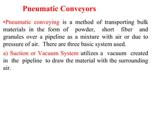
- 1. Pneumatic Conveyors •Pneumatic conveying is a method of transporting bulk materials in the form of powder, short fiber and granules over a pipeline as a mixture with air or due to pressure of air. There are three basic system used. a) Suction or Vacuum System utilizes a vacuum created in the pipeline to draw the material with the surrounding air.
- 2. • These systems are particularly suited to moving material from • multiple pickup points to a the reason single location, being that the bulk expense system's terminal receiver, end rotary where valves, of the is in the the and vacu u m source are located.
- 3. Pneumatic Conveyor - Vacuum System
- 4. b) Pressure-type System is ideally suited for conveying from one pickup Location to many discharge locations. Generally,this type of system is more economical when going from one point to several. A pressure system of this type generally conveys with a product-to-air ratio of about 20kg of material per kg of air, or approximately 24kg of material/m3 of air (or 20 m3 of air/m3 of product).
- 5. Cont’d Pneumatic Conveyor -Pressure System
- 6. C)Combination System (Push-Pull system) This is a system in which a sanction (permit) system is used to convey material from a number of loading points and pressure system is employed to deliver it to a number of unloading points. Such installations are utilized when conveying over a long distance is required. Applications and Limitations: Pneumatic conveyors have many advantages: •delivery of materials over a path capable of changing its direction in any plane,
- 7. processing of the material simultaneously with its conveying, an almost limitless number of loading and unloading points served by a single system, air and gas tightness eliminating dust nuisance (pains) and dust hazards an almost totally automated conveying with considerable reduction of losses of material, improved labor conditions and minimum of human attendance.
- 8. The limitations of the system are high power requirements (15kWh/t, 10 to 15 times higher than mechanically conveyors), rapid wear of equipment, the problem of dust recovery from the exhaust air inability to convey wet, caking (block) and sticky loads.
- 9. Pneumatic Conveyor Components Intake Units One of the most delicate problems in pneumatic conveyors is the introduction of material to the flow of air at a regulated rate a. Nozzle Injector Nozzle Injector
- 10. b. Rotating Valve Rotating Valve Stationary Screw Feeder
- 11. Cont’d Suction Nozzle Conveying Pipe and Changeover Valves
- 12. Cont’d Separator
- 13. Design Considerations In pneumatic conveyor calculations given are properties of the material, required capacity Q tons per hour and the configuration of the conveying pipe. Required are: 1. Calculated (reduced) conveying length, Lred [m]
- 14. Values of Equivalent Lengths for Elbows Material 4 6 10 20 Powdered 4-8 5-10 6-10 8-10 Granular Homogenous - 8-10 12-16 16-20 Small Lumped Irregular - - 28-35 38-45 Large Lumped Irregular - - 60-80 70-90 The commonly used value for a two-way changeover valve L= 8m. eqv
- 15. 2. Conveying air stream velocity, = [m/s] air 1 v BL2 red Values of Factor for the Size of Load Particles Material Particle Size Powdered 1-1000(micron) 10-16 Granular Homogenous 1-10mm 17-20 Small Lumped Homogenous 10-20mm 17-22 Medium Lumped Homogenous 40-80mm 22-25 Where, = factor for the size of load particles γ1 = specific weight of the load particles[tons/m3 ] B = factor assumed as equal to (2 to 5) 10-5 , the lower values being taken for dry powder materials.
- 16. 3. Weight concentration of the mixture, : Graph Showing the Dependence of the Weight Concentration of the Mixture on the Reduced Conveying Length . Lred
- 17. Note:Graph (1): 4 air 2 p air ol 3.6 Q v d V where Q = capacity of installation [tons/hour]
- 18. 5. Conveying pipe inner diameterd , p [m] air p v 4Vol d 6. The required air pressure in the pipe, [kg/cm2] 104 Hair cs P Where, air= specific weight of the air (average for a given vertical section).
- 19. For pressure conveying system; cs p red air i P d 2 P 1 L v red air d p 2 L v Where, = a factor; for pressure conveying systems, depends on the value of s = 1.510 7 and for suction and for suction conveying system: And for suction conveying system cs p red air f P d 2 L v P 1
- 20. • The plus sign before in equation is taken for upward, the minus sign for downward movement. Graph Showing the Dependence of Factor the Value of s on
- 21. 7. The required air pressure of the compressor or air blower, [kg/cm2] Pb Pw Ploss w Where, P = working pressure = for pressure conveying system , = suction conveying syste,m Pi Po Pf loss P Ploss 0 = 1.15 to 1.25 factor for losses in the intake unit, = pressure loss in the supplying air for compressors, P = 0.3 kg/cm2, = atmospheric pressure = 1atm.
- 22. 8. The required capacity of the compressor or blower, [m3/min] 4 2 p air v ' o ol d V V ' where , =' factor for losses due to leaks = 1.1.
- 23. 9. The required motor power, [kW] 1 m3 drawn in during isothermal compression [kgm/m3]. = total efficiency of compressors =0.55 to 0.75. Where, Lb = theoretical work of the blower reduced to . 0 0 P Pb b L 23,030 P log 60102 LbVo b N