

Recommended
More Related Content
Similar to exp1 control lab.pdf
Similar to exp1 control lab.pdf (20)
More from Mahamad Jawhar
More from Mahamad Jawhar (20)
Recently uploaded
Recently uploaded (20)
exp1 control lab.pdf
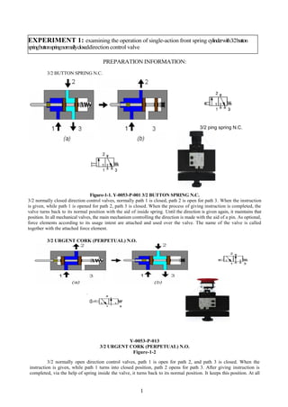
- 1. 1 EXPERIMENT 1: examining the operation of single-action front spring cylinderwith3/2button springbuttonspringnormallycloseddirection control valve PREPARATION INFORMATION: 3/2 BUTTON SPRING N.C. Figure-1-1. Y-0053-P-001 3/2 BUTTON SPRING N.C. 3/2 normally closed direction control valves, normally path 1 is closed, path 2 is open for path 3. When the instruction is given, while path 1 is opened for path 2, path 3 is closed. When the process of giving instruction is completed, the valve turns back to its normal position with the aid of inside spring. Until the direction is given again, it maintains that position. In all mechanical valves, the main mechanism controlling the direction is made with the aid of a pin. As optional, force elements according to its usage intent are attached and used over the valve. The name of the valve is called together with the attached force element. 3/2 URGENT CORK (PERPETUAL) N.O. Y-0053-P-013 3/2 URGENT CORK (PERPETUAL) N.O. Figure-1-2 3/2 normally open direction control valves, path 1 is open for path 2, and path 3 is closed. When the instruction is given, while path 1 turns into closed position, path 2 opens for path 3. After giving instruction is completed, via the help of spring inside the valve, it turns back to its normal position. It keeps this position. At all 3/2 ping spring N.C.
- 2. 2 mechanic valves, the main mechanism, that makes the direction control, carries out this through a pin. As optional, force elements are attaches over valve according to its usage intent. The name of the valve is called by the attached force element. Emergency stop valve is used in order to shut down the pressure of the system and to release the pressure air within the system during the failure, breakdown or operator accidents likely to happen in the system of the pneumatic circuits. MATERIALS TO BE USED IN THE EXPERIMENT Y-0053-P-000 COMPRESSOR Y-0053-P-013 3/2 URGENT CORK (PERPETUAL) N.O. Y-0053-P-044 FILTER REGULATOR Y-0053-P-049 DISTRIBUTION BLOCK Y-0053-P-001 3/2 BUTTON SPRING N.C. Y-0053-P-073 SINGLE-ACTION CYLINDER FRONT-SPRING 20X50 Y- 0053-P-100 PNEUMATø~C HOSE 4 mm CIRCUIT SCHEME Figure-1-3
- 3. 3 EXPERIMENTATION: Picture-1-1 1- Place the pneumatic materials over an aluminum profile plate as shown in Picture-1-1 Make the pneumatic hose connections. 2- The pressure air from compressor stands at the filter regulator inlet over the 3/2 urgent cork (perpetual) N.O. valve. By adjusting the filter regulator to 4 bar value that we shall use in the experiments, we confirm its accuracy over manometer. 3- Pressure air reaches the distribution block as 4 bar value. We can get pressure air when required from all outlets over the distribution block. The pressure air stands in the pressure air inlet 1 of 3/2 button spring N.C. valve. 4- What is the position and what is the reason of single-action front spring cylinder? 5- Hold down the button of 3/2 button spring N.C. valve. What happened to the position of the valve? 6- What is the position and what is the reason of the cylinder? 7- What shall be the position of the valve and position of the cylinder, when we remove our hands over button? 8- Pressing the button, start to lower the value of filter regulator, what happened to the cylinder’s motion and its pressure value? 9- Increase the regulator pressure to 4 bar, when pressed to button and when we remove our hand from the button, what happened to the movement direction and forces of stern-spring single- action cylinder with a diameter of 20 mm, mile diameter of 8 mm? (It should be yield = 100%, π = 3,14.) 10. Find the actual repulsive force F= P*A*η. Where η is the efficiency of the system. If F= f1 – f2, where, f1 is the repulsive force and f2 roll-back spring of cylinder.