CCS355 Neural Network & Deep Learning Unit II Notes with Question bank .pdf
Lab pactice on pneumatic control systems
1. 1
Lab practice pneumatic control system
Practice No.1
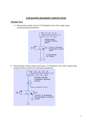
1. Demonstratea simple circuit of 3/2 Pushbutton valve with a single acting
actuator(including simulation):
2. Demonstratean actuator speed control using a 3/2 Pushbutton valve with a single acting
actuator and flow control valve (including simulation):
2. 2
3. Demonstratea 3/2 pushbutton valve, a 5/2 Pilot controlled pneumatic valve and a double
acting actuator (including simulation):
4. Demonstratedouble acting actuator speed control using a 3/2 pushbutton valve, a 5/2
Pilot controlled pneumatic valve and two flow control valves (including simulation):
3. 3
5. Demonstratethe OR Logic circuit using two 3/2 pushbutton valves, a shuttle valve and a
single acting actuator(including simulation):
6. Demonstrate the AND circuit using two 3/2 pushbutton valves, a two pressure valve and
a single acting actuator (including simulation):
4. 4
7. Demonstratesemi-automatic circuit using a 3/2 pushbutton control valve, a 3/2 roller
lever valve, a 5/2 pilot valve, a single and a double acting actuator (including
simulation):
8. Demonstratefully automatic circuit using a 5/2 Solenoid control valve, a Single and a
Double acting actuator. Control is achieved using a feedback signal to the PIC Logicator
interface board and Software: Fully Automatic Pneumatic Circuit
5. 5
Practical No. 2
AIM: study of reciprocating movement of double acting cylinderusing pneumatic directional
control valves
INTRODUCTION
A double acting cylinder is to advance when a push button is operated. Upon release of the push
button the cylinder is to retract. The cylinder is 250mm in diameter and consumes a large volume
of air. Draw the circuit diagram of for the problem. Designate the valves and indicate the
numbering system for the connections.
For controlling cylinders at high speed or of large diameter, the air flow required determines that
a large size control valve should be used. The operating force to actuate the valve may be
relatively large and in this case indirect control is preferable.
A 4/2-way or 5/2-way directional control valve controls the double acting cylinder if the piston is
not to be stopped in between 4/3-way or 5/3-way direction control valve controls the cylinder in
which the piston can be stopped anywhere required.
A signal is generated or reset on the valve, if a push button actuator is pressed or released. The
circuit includes;
6. 6
Supply air source (compressor)
Air connections among supply
Unit for conditioning of air
Double acting cylinder
4/2-way5/2-way4/3-way5/3-way DC valve: push button and lever for operation and
spring for return force
Adjustable non return flow control valves for speed control (throttling out)
Fluid lines
Practical No. 3
AIM: design of reciprocating movement of double acting cylinderusing pneumatic directional
control valves applicable for vehicle door operation system
INTRODUCTION:
Pneumatic systems can be used to operate the doors of public vehicles. Assuming
that the opening and closing of the doors are controlled by two button switches
“ON” and “OFF”. When the button switch ON is pressed, the doors will be open
whereas when the button switch OFF is pushed, the doors will be closed.
Figure: Operation of a pneumatic system that controls the movement of vehicle doors
7. 7
Practical No. 4
AIM: design of reciprocating movement of double acting cylinder using pneumatic directional
control valves applicable for industrial transport system
INTRODUCTION:
Pneumatic systems can be used to transport goods in industries. When the button
switch is pushed, the cylinder will push one of the goods from the shelf onto the
transfer belt. When the button switch is released, the cylinder will retract
automatically.
Figure: Operation of a pneumatic transport system