1. Combinational Logic Circuits
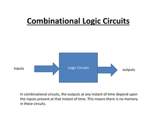
Logic Circuits
Inputs outputs
In combinational circuits, the outputs at any instant of time depend upon
the inputs present at that instant of time. This means there is no memory
in these circuits.
2. Half Adder
A logic circuit for the addition of two one-bit
numbers is referred to as an Half adder.
3.
4. Full Adder
A logic circuit for the addition of three one-bit
numbers is referred to as an Full adder.
Or
An half adder has only two inputs and there is
no provision to add a carry coming from the
lower order bits when multibit addition is
performed.
7. Half Subtractor
A logic circuit for the subtraction of
B(subtrahend) from A minuend) where A and B
are 1 –bit number is referred to as a half
subtractor.
8.
9. Full Subtractor
A full subtractor will have three inputs,
A(minuend),B(subtrahend) and Cin(borrow from
the previous stage) and two output, D(different)
and Cout(borrow).
12. Digital Comparator/Compaartor
A logic circuit that compares two numbers and
produces as output indicating whether they are
equal or which is greater if they are unequal.
13. TRUTH TABLE
A B AGB(A>B) AEB(A=B) ALB(A<B)
0 0 0 1 0
0 1 0 0 1
1 0 1 0 0
1 1 0 1 0
26. Parity Generators/Checkers
The concept of parity, wherein an additional bit known as the parity-bit is added
to a binary word to make the number of 1’s in the new word formed, even(even
parity) or odd(odd parity), has been discussed. The circuit for the generation of
parity bits and checking the parity of a given word can be designed using gates.