Download as PDF, PPTX


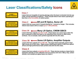


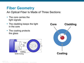

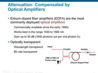


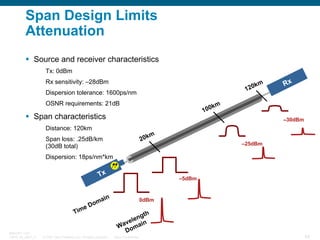
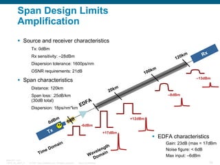
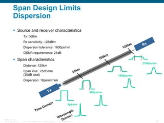
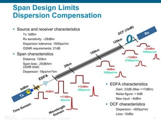

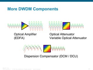
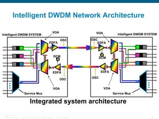


The document provides an overview of optical DWDM fundamentals, including terminology, fiber characteristics, and transmission effects. It discusses key topics such as optical propagation in fibers, attenuation and compensation using optical amplifiers, dispersion types and limitations, and wavelength grids. Diagrams and examples are used to illustrate optical power measurements, budgets, safety classifications, and the impacts of attenuation and dispersion on transmission performance.


![DWDM & Packet Optical Fundamentals by Dion Leung [APRICOT 2015]](https://cdn.slidesharecdn.com/ss_thumbnails/dwdmpackettutorialapricot20151425453497-150304173624-conversion-gate01-thumbnail.jpg?width=640&height=640&fit=bounds)


