2. American Journal of Orthodontics and Dentofacial Orthopedics Shroff et al. 137
Volume 107, No, 2
continuous arch wire with tip back bends located
mesial to the first permanent molars may not
achieve intrusion because the full engagement of
the arch wire in the brackets of the anterior teeth
produces an undesirable force system. In these
cases, relative intrusion and flaring of the anterior
teeth are achieved, resulting in a modification of
the axial inclination of the anterior teeth that may
or may not be desirable.7
The selection of the point of application of the
intrusive force with respect to the center of resis-
tance of the anterior segment is important to pre-
cisely define the type of tooth movement that will
occur. True intrusion without axial inclination
change is obtained by directing the intrusive force
through the center of resistance of the anterior
teeth. Since displacement of the intrusive force
away from the center of resistance will result in
either flaring or uprighting of the incisors, careful
evaluation is necessary to monitor the axial incli-
nation of the anterior teeth during intrusion.8
In patients with proclined incisors, a continuous
intrusion arch tied at the midline cannot be used
because the force system generated tends to
worsen the axial inclination of the anterior teeth.
This is because the intrusive force is applied ante-
rior to the center of resistance of the incisors and
the moment consequently produced tends to fur-
ther flare the anterior teeth. One solution to this
problem is the use of distal extensions to the
anterior segment of wire where segmented intru-
sion springs can be hooked at a point where the
force acts at the estimated center of resistance of
the anterior segment.9
In many extraction cases the axial inclination of
flared anterior teeth is corrected first by retraction
of the incisors during initial space closure. When
no further retraction is possible because of the
presence of a deep bite and the reduction of the
overjet, intrusion is initiated to open the bite and
allow subsequent space closure. To achieve deep
overbite correction and close extraction spaces si-
multaneously,an appliance design needs to incor-
porate a variable point of application of the intru-
sive force, as well as a mechanism to direct the
intrusive force along the long axis of the anterior
teeth.
~NTRUSION- RETRACTION MECHANICS
The mechanism described here uses the prin-
ciples of the segmented arch technique.~° Seg-
mented arch mechanics uses different wire cross-
sections in a given arch rather than continuous
wires?~The advantage of using such an approach is
that it is possible to develop a precise and predict-
able force system between an anterior segment
(incisors) and a posterior segment (premolar and
molars) enabling pure intrusion of the anterior
teeth and control of their axial inclinations. Move-
ment of the posterior segment is also well con-
trolled. The appliance described enables the mag-
nitude of the moments and forces delivered to be
well controlled.12 Consequently, constant levels of
force can be maintained, and the moment to force
ratio (M/F) at the centers of resistance easily regu-
lated to produce the desired tooth movements.
Sometimes, intrusive forces on the upper ante-
rior teeth can be used to tip back the posterior
teeth while partially or completely correcting a
Class II buccal relationship. This article will em-
phasize the use of intrusive forces for retraction of
anterior teeth when intrusion is needed. The same
mechanism with higher forces can be used to tip
back buccal segments. If only anterior intrusion
and retraction is indicated, the following proce-
dures are generally followed.
After careful differential diagnosis and plan-
ning, treatment is initiated by aligning the teeth
included in the right and the left posterior seg-
ments. After satisfactory alignment of the premo-
lars and molars, passive segmented wires (0.017 x
0.025 stainless steel) are placed in the right and the
left posterior teeth for stabilization. A precision
stainless steel transpalatal arch (0.032 × 0.032)
placed passively between the first maxillary molars
consolidates the posterior unit now consisting of
right and left posterior teeth.13 Canines may be
retracted separately and incorporated into the buc-
cal segments14'~5 or left at their initial positions.
The anterior segment is aligned with a low stiffness
arch wire. The next stage of treatment will involve
the simultaneous intrusion and retraction of the
incisor segment. To design the appliance optimally
to obtain the desired force system, the position of
the center of resistance of the anterior teeth may
be estimated on a lateral cephalometric x-ray film.
In clinical situations where incisors are proclined,
the center of resistance of the anterior segment lies
further lingual to the incisors crowns.
A three-piece base arch is used to intrude the
anterior segment (Fig. 1). A heavy stainless steel
segment (0.018 x 0.025 or larger) with distal exten-
sions below the center of resistance of the anterior
teeth is placed passively in the anterior brackets.
The distal extensions end 2 to 3 mm distal to the
center of resistance of the anterior segment. The
intrusive force is applied with a 0.017 × 0.025
TMA tip-back spring (Ormco, Glendora, Calif.).
3. 138 Shroff et aL American Journal of Orthodontics and Dentofacial Orthopedics
February 1995
Fig, 1, Diagramaticrepresentation of three-piece base arch. The anterior segment extends 2 to 3 mm
distal to the center of resistance (CR) of the anterior teeth. Force acts through center of resistance.
Fig, 2. Diagram of three-piece base arch and Class I elastic
stretched from maxillary first permanent molar to distal exten-
sion of anterior segment. Class I elastics are needed to
redirect force parallel to the long axis of the incisor.
(The point of application of the intrusive force on
the distal extension of the anterior segment will be
discussed later.) The overall force system obtained
is an intrusive force anteriorly and an extrusive
force posteriorly associated with the tip back mo-
ment. The design of this appliance enables low-
friction sliding to occur along the distal extension
of the anterior segment during space closure (Fig.
2). The application of a light, distal force delivered
by a Class I elastic to the anterior segment is used
to alter the direction of the intrusive force on the
anterior segment. This appliance design allows the
application of the intrusive force to get true intru-
sion of the incisors along their long axes.
Fig. 3. A, Intrusive force through CR will intrude incisor along
line of action of this force. B, An intrusive force perpendicular
to the distal extension and through CR will have the same
effect as in A.
BIOMECHANICS
Anterior segment and direction of intrusive force
A number of different clinical situations may
arise and they should be thoroughly analyzed from
a biomechanical standpoint to determine the cor-
rect force system necessary to achieve the treat-
ment objectives.
An intrusive force perpendicular to the distal
extension of the anterior segment and applied
through the center of resistance of the anterior
teeth will intrude the incisor segment (Fig. 3). It is
possible to change the direction of the net intrusive
force by applying a small distal force. The line of
4. American Journal of Orthodonticsand Dentofacial Orthopedics Shroff et aL 139
Volume 107,No. 2
Fig. 4. A, Direction of net intrusive force through CR may be
changed by application of a small distal force. The resulting
intrusive force has a direction parallel to the long axis of the
incisor and is distal to CR. B, The net force can be directed
along the long axis of the incisor by applying the intrusive
force more anteriorly.
action of the resultant force will be lingual to the
center of resistance (Fig. 4, A) and a combination
of intrusion and tip back of the anterior teeth will
occur. Thus the line of action of the resultant force
can be made parallel to the long axis of the anterior
teeth if an appropriate distal force is combined
with a given intrusive force. To obtain a line of
action of the intrusive force through the center of
resistance and parallel to the long axis of the
incisors, the point of force application must be
more anterior and as close to the distal of the
lateral incisor bracket as possible (Fig. 4, B).
If the intrusive force is placed farther distally
and an appropriate small distal force is applied
(Fig. 5), intrusion and simultaneous retraction of
the anterior teeth occurs because of the tip back
(clockwise) moment created around the center of
resistance of the anterior segment consisting of
four incisors.
The distal force used in this intrusion retraction
system is of very low magnitude and is used to
redirect the line of action of the intrusive force.
One advantage of this system is the low magni-
tude of force applied on the reactive or anchorage
unit.
CLINICAL APPLICATIONS OF THE INTRUSION
RETRACTION MECHANICS
After treatment planning and developing treat-
ment objectives, the desired force system should be
determined with respect to the centers of resis-
Fig. 5. intrusive force can be directed along long axis of
anterior teeth and applied lingual to CR. The farther lingual the
force, the larger will be the moment acting to tip the incisors
lingually.
tance of the anterior and posterior segments. The
correct appliance design is chosen after careful
analysis of the clinical situation as discussed above.
Spacing or crowding among the incisors is usually
addressed early in treatment. When intrusion-
retraction mechanics are initiated, the anterior
teeth will intrude and tip back with progressive
space closure between the incisors and the canines.
Distal movement of the canines may occur as the
anterior segment contacts the canines. It is also
possible to retract the canines indMdually and to
include them in the buccal stabilizing segment of
wire before the initiation of intrusion-retraction
mechanics.
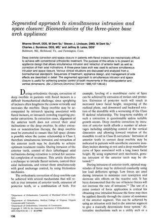
The force system generated on a molar is shown
in Fig. 6, A. A tip back moment is created during
intrusion of the anterior segment and will have a
typical value of 900 gm-mm for an intrusive force of
30 g and an interbracket distance of 30 mm. In Fig.
6, B, the force is redirected to be parallel to the
long axes of the incisors. Redirection and move-
ment of the intrusive force distally reduces the
moment on the buccal segment of teeth, and thus
reduces the tendency for its natural plane of occlu-
sion to steepen. Headgear is not usually required
for anchorage control, since a net tip back moment
is applied to the posterior segment. It is important
to monitor the anterior and posterior segments and
alter the force system if indicated. The resulting
force system can be modified by changing the
magnitudes and points of application of the intru-
sive and distal forces with respect to the center of
resistance of the anterior segment.
5. 140 Shroff et aL American Journal of Orthodontics and Dentofacial Orthopedics
February 1995
gl
ao turn -----"~1
gr
B
Fig. 6. Comparison of force system developed on molar with identical 30 gm intrusive forces. A,
Perpendicular to the occlusal plane. B, Parallel to the incisor long axis and lingual to CR. Note
reduction of the moment on the molar in B.
CASE REPORT
A 10-year, 9-month-old black female patient pre-
sented to the orthodontic clinic of UMAB Dental School
for treatment. The extraoral examination of the patient
showed good facial symmetry and a convex profile. Her
upper and lower lips were significantly procumbent with
respect to the soft tissue line Sn-Pg (subnasale-Pogo-
nion), and her interlabial gap was 9 mm at rest. She
presented with an acute nasolabial angle and a deep
labiomental fold.
Dentally, the patient displayed a Class II, Division 1
malocclusion in the late mixed dentition (Fig. 7). The
occlusogram confirmed 11 mm of spacing in the maxillary
arch. The anterior overjet was approximately 10 mm, and
the overbite was 65%, with palatal impingement. A deep
curve of Spee was present in the mandibular arch. The
patient had a Class II skeletal relationship primarily
because of a protrusive maxilla. The upper incisors were
labially tipped with respect to Frankfort horizontal, and
the lower incisors were in relatively normal position with
respect to the mandibular plane. The treatment objec-
tives included a reduction of the maxillary protrusion
both orthopedically and dentally, correction of the deep
overbite, and achievement of maxillary space closure.
Deep overbite was corrected by upper and lower incisor
intrusion. In the maxillary arch, rotation of the first
molars was achieved initially with a removable stainless
steel transpalatal arch. High-pull headgear wear was
initiated to correct the Class II occlusion and control the
vertical dimension. Simultaneous intrusion and retrac-
tion of the upper incisors was initiated after consolida-
tion of spaces in the maxillary arch between the lateral
and central incisors. Because of the proclination of the
maxillary incisors, a three-piece base arch was selected to
intrude them and a light distal force was applied to
redirect the intrusive force along their long axes.
As intrusion occurred, the incisors tipped back and
space closure was achieved simultaneously (Fig. 8). A
continuous intrusion arch tied to the central incisors
could not have been used in this situation because of the
proclined position of the upper incisors. The application
of an intrusive force anterior to the center of resistance
6. American Journal of Orthodontics and Dentofacial Orthopedics Shroff et aL 141
Volume 107, No. 2
Fig. 7. A, Intraoral view of occlusion: Frontal aspect. There is a 65% overbite with palatal impinge*
ment and an anterior overjet of 10 mm. B, Intraoral views of the occlusion, maxillary occlusal view.
The maxillary arch is symmetric with respect to the median Raphe and the soft tissue of the cheeks
and lips. The maxillary arch has 11 mm of spacing confirmed by the occlusogram. C and D, Intraoral
views of the right and left buccal occlusion showing a deep curve of Spee in the lower arch and a
Class II, Division 1 type of malocclusion in the late mixed dentition. The maxillary anterior teeth are
in tabioversion.
Fig. 8. A, Intraoral view of occlusion: Frontal aspect. After preliminary alignment of the molars and
premolars and separate retraction of the canines, a three-piece base arch was used to simulta-
neously intrude and retract the maxillary incisors. B and C, Intraoral views of the right and left buccal
occlusion: The tip back spring is carefully positioned and activated. The chain elastic is redirecting
the intrusive force along the long axes of the maxillary incisors.
7. 142 Shroff et al. American Journal of Orthodontics and Dentofacial Orthopedics
February 1995
Fig. 9. Intraoral views of finished occlusion: A, Frontal aspect. B, Maxillary occlusaq aspect. C,
Mandibular occlusal aspect. D and E, Right and left buccal aspects.
BEFORE
...... AFTER
Fig. 10. Superimposition of maxillary cephalometric tracings
before and after treatment showing movement of maxillary
incisors and molars during treatment. The intrusive force
applied on the maxillary incisors was redirected along their
long axis and simultaneous intrusion and space closure was
successfully achieved.
of the anterior segment would have flared the incisors
farther. The upper arch was finished with a continuous
arch wire (0.016 x 0.022 TMA). In the mandibular arch,
a removable lingual arch was placed, and intrusion of the
incisors was achieved with a continuous intrusion arch.
After the leveling of the curve of Spee, a continuous arch
wire (0.017 × 0.025 TMA) was used for finishing. The
three-piece base arch allowed precise control of the
delivered force system in the maxillary arch, since it was
possible to direct the intrusive force along the long axes
of the incisors and place it lingual to the center of
resistance. Maxillary and mandibular Hawley retainers
were delivered to the patient subsequent to debonding
(Fig. 9). A superimposition of maxillary cephalometric
tracings before and after treatment shows the movement
of the maxillary incisors and molars during treatment
(Fig. 10).
CONCLUSION
Deep overbite correction and space closure can
be simultaneously achieved with the three-piece
8. American Journal of Orthodonticsand Dentofacial Orthopedics Shroff et aL 143
Folume 107,No. 2
base arch intrusion mechanism in patients with
flared incisors. The force system delivered on the
anterior segment depends on the point of applica-
tion of the intrusive force and its direction. This
segmented approach to intrusion and retraction is
clinically advantageous because it allows simulta-
neous control of tooth movement in the vertical
and anteroposterior planes. The low load deflec-
tion rate of this appliance delivers a constant in-
trusive force, and the levels of force can be kept
low. The design of this appliance allows the clini-
cian to deliver a well-controlled, statically determi-
nate force system in which only minimal chairside
adjustments are required.
We extend our thanks to Mrs. Jo-Ann Walker for
preparing the manuscript.
REFERENCES
1. Burstone CA. Deep overbite correction by intrusion. AM J
ORTHOD 1977;72(1):1-22.
2. Burstone CJ, Baldwin JJ, Lawless DT. The application of
continuous force to orthodontics. Angle Orthod 1961;31:1-
14.
3. Burstone CA. The rationale of the segmented arch. AM J
ORTHOD 1962;48(11):805-21.
4. Burstone CJ. Mechanics of the segmental arch technique.
Angle Orthod 1966;36(2):99-120.
5. Dellinger EL. A histologic and cephalometric investigation
of premolar intrusion in the Macaca speciosa monkey. AM J
ORTHOD 1967;53:325-55.
6. Reitan K. Initial tissue behavior during apical root resorp-
tion. Angle Orthod 1974;44(1):68-82.
7. Begg PR, Kesling PC. Begg orthodontic theory and tech-
nique. Philadelphia: WB Saunders: 1977:203-14.
8. Smith RJ, Burstone CJ. Mechanics of tooth movement. AM
J ORTHOD 1984;85(4):294-307.
9. Romeo DA, Bnrstone CJ. Tip-back mechanics. AM J
ORTHOD 1977;72(4):414-21.
10. Bnrstone CJ. Applications of bioengineering to clinical
orthodontics. In: Graber TM, ed. Current orthodontic con-
cepts and techniques, I. 2rid ed. Philadelphia: WB Saunders,
1985.
11. Burstone CJ. Variable modulus orthodontics. AM J
ORTHOD 1981;80(1):1-16.
12. Burstone CJ, Koenig HA. Optimizing anterior and canine
retraction. AM J ORTHOD 1976;70:1-20.
13. Burstone CJ, Manhartsberger C. Precision lingual arches-
passive applications. J Clin Orthod 1988;22(7):444-51.
!4. Burstone CJ. The segmented arch approach to space clo-
sure. AM J ORTHOD 1982;82(5):361-78.
!5. Manhartsberger C, Morton J, Burstone CJ. Space closure in
adult patients using the segmented arch technique. Angle
Orthod 1989;59:205-10.
Reprint requests to:
Dr. Bhavna Shroff
Department of Orthodontics
University of Maryland Dental School
666 West Baltimore St.
Baltimore, MD 21201
AAO MEETING CALENDAR
1995 -- San Francisco, Calif., May 12 to 17, Moscone Convention Center
(International Orthodontic Congress)
1996 - Denver, Colo., May 11 to 15, Colorado Convention Center
1997 - Philadelphia, Pa., May 3 to 7, Philadelphia Convention Center
1998 - Dallas, Texas, May 16 to 20, Dallas Convention Center
1999 - San Diego, Calif., May 15 to 19, San Diego Convention Center
2000 - Chicago, II1., April 29 to May 3, McCormick Place Convention Center