
Recommended
Recommended
More Related Content
What's hot
What's hot (20)
Similar to Intrusion PEREPERD BY DR.ABDULGHANI ALMOHAYA ,ALHADDAD.pptx
Similar to Intrusion PEREPERD BY DR.ABDULGHANI ALMOHAYA ,ALHADDAD.pptx (20)
Recently uploaded
Recently uploaded (20)
Intrusion PEREPERD BY DR.ABDULGHANI ALMOHAYA ,ALHADDAD.pptx
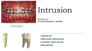
- 1. Intrusion PREBERD BY ABDULQ AWI ABDULGHANI ALHADDAD ABDULSALAM ABDALWAHAB PRESENTED TO Dr. Laraine Rowena L. Andrada
- 2. Introduction Intrusion refers to the apical movement of the geometric center of the root (centroid) in respect to the occlusal plane or plane based on the long axis of the tooth. Burstone Marcotte defines intrusion as the” tooth movement that occurs in an axial (apical) direction and whose center of rotation lies at infinity. It is an axial type of translation” Nicolai as “ translational form of tooth movement directed apically and parallel to the long axis”
- 3. Correction of the deep overbite can be accomplished in a number of ways depending on the initial diagnosis and treatment objectives. Deep bite can be corrected by various tooth movements which include: Extrusion of posterior teeth Up righting of posterior teeth Increasing the inclination of incisors Intrusion of anterior teeth Combination of one or two of the above tooth movements Intrusion of anterior teeth to correct deep overbite may be indicated in patients with unaesthetic excessive maxillary incisor showing at rest position of the lip (5-8mm)
- 4. Pseudo intrusion refer to the labial tipping of the incisor around the centroid. Relative intrusion – Deep bite correction by extrusion of posterior teeth rather than true intrusion of the anterior teeth
- 5. True intrusion is obtained by applying a single intrusive force through the center of resistance of the anterior teeth. The precise selection of the point of application of the intrusive force with respect to the axial inclination of the incisors is critical and will define the type of tooth movement If the incisors are flared and the intrusive force is applied anterior to the Cres further flaring occurs so to prevent this force should be applied distally in order to direct the force passes through the Cres Biomechanics In Intrusion
- 7. Major Principles Of Intrusion Six major principle of intrusion should be followed; if genuine intrusion and greater control of force system is needed: 1. Controlling force magnitude and constancy. 2. Anterior single point contacts. 3. Point of force application. 4. Selective intrusion. 5. Control of reactive units. 6. Avoiding extrusive mechanics.
- 8. In order to maintain a constant force during intrusion, wire with a low load deflection rate should be used. If a high load deflection spring is used for intrusion as teeth moves, a rapid drop in force magnitude occurs, so that optimal force may be only momentarily reached.
- 9. POINT OF FORCE APPLICATION Passing through center of resistance Intrusion of incisor segment Passing labial to the center of resistance Flares the crown more labially
- 10. SELECTIVE INTRUSION Leveling with a continuous arch or with a sectional wire can produce undesirable side effects. Many times the overbite is corrected not because of intrusion but by extrusion.
- 11. Control Of The Reactive Unit Two basic side effects should be anticipated from intrusive mechanics From the lateral view a moment is created which tends to alter the plane of occlusion of the buccal segment and therefore in the upper arch, the plane is steepened. 1.The force are kept as low as possible 2.Teeth in the buccal segment are rigidly connected and the right and the left buccal stabilizing segment are connected 3.So add more teeth for anchorage 4.Do as much retraction as possible to decrease the length of moment arm
- 12. . Second major side effect produced by an intrusive arch can be seen from the frontal view with an intrusive force acting on the incisors, there is an equal and opposite extrusive force acting at the molars. since the extrusive force is acting buccally at the tube, a moment is created that tends to tip the crowns lingually and roots buccally. One of the functions of the lingual arch is to resist side effects
- 13. It is wise to intrude the maxillary incisors to a significant degree prior to any retraction: 1. Bite opening is achieved by moving maxillary incisors into the alveolus. 2. The potential for increasing a gummy smile is minimized. 3. The unfavorable tipping of the occlusal cant will not be as common. 4. It will minimize the chances of moving the apices into the dense cortical bone. 5. There will be a reduction in the total amount of class II elastics that will be required. 6. The torquing requirements will be reduced.
- 14. Intrusion Force
- 15. Proffit suggested 10-20 grams of force needed for intrusion. Bench, Gugino and Hilgers in 1978, advocated intrusive force of 15 to 20 grams per lower incisor and 60 to 80 grams for all four lower incisors. Lui and Herschelb in 1981 suggested use of 80 to 100 grams of force for four incisors intrusion. Though there has been many opinions regarding an ideal force for intrusion, all recognize the need for light continuous force
- 16. Appliance for intrusion The extraoral traction force can be attached anteriorly by means of j hook to the arch wire or to a hook soldered to the arch wire. J –hook can be applied to the maxillary teeth to retract and intrude the maxillary incisor teeth. The line of force passing mesial and apical to the center of resistance causes intrusion and distalize upper incisors. Head Gear + Maxillary intrusion splint = For whole Arch Intrusion. J Hook Head Gear
- 17. ANCHORAGE BENDS / TIP BACK BENDS Placed immediately posterior to the 2nd premolar bracket • Bent so that when inserted into the buccal tubes the anterior section of the arch wire lies in the buccal sulci Causes intrusion of anteriors.
- 18. GABLE BEND Modified bite opening bend given in the arch wire distal to the canine This tends to cause relative extrusion of canines and intrusion of central and laterals
- 19. Given by Richard A. Hocevar, Bite opening bends are placed on either side of the canines, which results in more intrusion of central incisors and relative extrusion of laterals and canines Hocevara’s Intrusion Bend Reverse curve of spee correct the deep bite by extrusion of the posteriors and intrusion and flaring of the anteriors BITE OPENING CURVES
- 20. Intrusion Arches Intrusion can be accomplished in two ways with intrusion arches. 1. With continuous arch wire that by passes the premolars and canine teeth. 2. With segmented base arch wire. So that there is no connection along the arch between the anterior and posterior segments and an auxiliary depressing arch.
- 21. 1. Ricket’s Utility Arch 2. Tip back Springs ( Intrusion Springs) 3. Burstone’s Continuous Intrusion Arch. 4. Burstone’s Three Piece Intrusion Arch 5. K-Sir (Kalra Simultaneous Intrusion And Retraction) 6. Connecticut Intrusion Arch 7. PG Retraction Spring 8. Translation Arch 9. Lingual Arch For Intruding And Up righting Lower Incisors
- 23. BIO – MECHANICS OF INTRUSION ARCHES One couple systems The end that is tied as a point contact • The end which is engaged in the bracket slot a force and a couple • 1-couple system couple is generated only at the site of full engagement It is statically determinate magnitudes of the forces and moments produced can be determined clinically after the appliance is inserted into the bracket. Two couple systems Both the ends of the wire is engaged into brackets Magnitudes of the forces and moments produced can not be determined clinically after the appliance is inserted into the bracket. • Because of the inability to measure force systems produced by 2-couple appliances clinically, they are referred to as being statically indeterminate
- 24. The basic mechanism for intrusion consists of three parts: 1. The posterior anchorage unit. 2. The anterior segment. 3. The intrusion arch itself.
- 25. Three-piece Intrusion Arch Consists of Posterior anchorage segment Anterior segment with posterior extension Intrusive cantilevers Sometimes chain elastics
- 26. Biomechanics Intrusive force through Cres will intrude incisor along line of action of this force. An intrusive force perpendicular to the distal extension and through Cres will have the same effect.
- 27. To obtain a line of action of the intrusive force through the center of resistance and parallel to the long axis of the incisors, the point of force application must be more anterior and a small distal force should be given If the intrusive force is placed farther distally and an appropriate small distal force is applied, intrusion and simultaneous retraction of the anterior teeth occurs because of the tip back (clockwise) moment created around the center of resistance of the anterior segment consisting of four incisors.
- 28. Temporary Anchorage Devices Factors to consider when placing mini-implants includes 1. Sufficient interdental bone 2. Less soft tissue irritation 3. Larger anterior segment According to Nanda the ideal location for placement of TADS for anterior intrusion is between the roots of the canine and lateral incisors The selection of the point of application of intrusive force with respect to Cres of the anterior segment Anterior intrusion with TADS
- 29. The Cres of the six anterior teeth is estimated to be halfway between the Cres of the four incisors and canine A light distal force was delivered by an E-chain to the anterior segment to alter the direction of the intrusive force , so that true intrusion of the anterior teeth could be achieved on their long axis
- 30. BIOMECHANICS FOR MOLAR INTRUSION Some of the common indications for molar intrusion are 1. Increased anterior facial height 2. To initiate auto-rotation 3. Prosthetic purpose : making space for prosthesis Increasing the interdental height.
- 31. INTRUSION OF SINGLE MOLAR • Force should be balanced Bucco-lingually and mesio-distally for pure intrusion. • Line of force should pass through the cres of molar : • Centre of occlusal table • Near the furcation area • Closer to the palatal root of maxillary molar. • Recommended insertion site of minis crews : • Buccal surface – mesial interdental area • Palatially – distal interdental area
- 32. Additional minis crews can be placed on either side of the alveolar slope to adjust the force direction. • Three or four minis crews are useful to prevent or correct the tipping of severely extruded molars.
- 33. INTRUSION OF MOLARS ON BOTH SIDES Symmetrical intrusion – intrusive force delivered through trans palatal bar connecting both molars Control of palatal tipping : 1. Expansion of TPA 2. Additional minis crews on buccal side Control of mesio-distal tipping ( sagittal direction) Minis crew should be inserted on the line connecting the central fossa of both molars
- 34. Intrusion of maxillary molars Engagement of rigid rectangular wire in buccal side Y- Plates are placed at the Zygomatic buttress. TPA in the palatal side – to prevent buccal tipping of the posteriors Magnitude of intrusive force : 400 g / side
- 35. Intrusion of maxillary molars When maxillary molars are intruded at the same level as anteriors , anterior segment is included with a continuous arch wire . Simultaneously, arch wire is ligated to the miniplates to intrude/ maintain their exact position for few months.
- 36. Intrusion Of Mandibular Molars •Anterior open bite with increased mandibular posterior height •L- plates placed at the molar region of the mandibular body. •Intrusive force of 400-500 gms/side •Lingual arch and lingual torque is given in the rectangular wire to prevent buccal flaring
- 39. REFERENCES Contemporary orthodontics- Proffit • Orthodontics-current principles and techniques- Graber , Vanarsdall, Vig • Charles J. Burstone “ Biomechanics of deep overbite correction” semin orthod 2001: 7: 26-33 • Bhavana Shroff, Steven J Lindauer , Charles J Burstone “ Segmented approach to simultaneous intrusion and space closure: biomechanics of three piece base arch appliance” Am J Orthod dentofac Orthop 1995:107: 136-43. • Richard J. Smith, Charles J. Burstone, “ Mechanics of tooth movement” vol 85, 294-307 • McNamara JA Jr. Utility arches. J clin orthod 1986;20:p.452-456. • Martina R. Paduano S. The Translation Arch. J Clin Orthod. 1997;3;11:p.750-753 • Nanda, R. and Uribe, F.A., 2009. Temporary Anchorage D
- 40. Thank you