
Recommended
Recommended
More Related Content
What's hot
What's hot (20)
Similar to Orthodontic retraction biomechanics for space closure and distalization using centre of resistance simulator [compatibility mode]
Similar to Orthodontic retraction biomechanics for space closure and distalization using centre of resistance simulator [compatibility mode] (20)
Recently uploaded
Recently uploaded (20)
Orthodontic retraction biomechanics for space closure and distalization using centre of resistance simulator [compatibility mode]
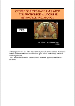
- 1. CENTRE OF RESISTANCE SIMULATOR FOR FRICTIONLESS & LOOPLESS RETRACTION MECHANICS DR. VISHNU JAGDISHBHAI PATEL M.D.S. CRS 1 Protruding dentition is one of the most common problems in Orthodontics. Distalization without extraction and extraction followed by space closure are two ways to retract protruding dentition. Centre of resistance simulator is an innovative customized appliance for Retraction Mechanics.
- 2. For bodily retraction, a line of action should ideally pass through centres of resistance of the segments to be moved. If it is not feasible practically. then at least the line of action must pass at the level of the Centres of Resistance in all 3 planes of space. 2 The concept is based on this principal of biomechanics.
- 3. ----10mm--- <---8mm--- --9mm--- 3 Let’s analyse sliding mechanics of space closure with continuous wire. The line of action is about 8, 9 AND 10mm occlusal from CR of Posterior teeth, entire system and CR of anterior teeth respectively.
- 4. 4 This force diagram is prepared to achieve pure bodily movement of the anterior teeth. Force values are for understanding purpose only. Applied force is about 200gm. Consider Sliding resistance about 100 gm, and therefore Force to overcome sliding resistance is 100 gm. In response to this 100 gm force, a clockwise moment of 900 gmmm is generated on entire system or dentition. Now coming to the actual space closure component: 100 gm retraction force on anterior teeth is balanced by 100 gm protraction force on posterior teeth. Because of 2mm shorter moment arm length of posterior teeth, 200gmmm of counterclockwise moment is felt by the entire system. So a net effect of 700 gmmm clockwise moment is felt by the entire system leading to bite deepening, which is undesirable in most of clinical situations except open bite cases requiring incisor extrusion. A reverse curve of spee can be placed in archwire to oppose this bite deepening moment on the system, but adverse effect is extrusion of posterior dentition which is undesirable for many reasons. This extrusion is fortunately opposed by muscle forces in horizontal growers and in normal growers up to some extent, but in long faces having poor muscle tone, this extrusion is always undesirable. Trans-palatal arch in patients with wide palate and normal tongue posture can be very helpful in such vertical growers. But in patients with narrow palate and lower tongue posture, TADS are required to prevent this extrusive component of the force system. This is how we achieve bodily retraction of the anterior teeth without bite deepening and without opening of the mandibular plane angle.
- 5. 5 Though We are achieving very much predictable results with sliding mechanics, CRS is having non-extrusive biomechanics and simple force diagram in comparison to sliding mechanics provided it is precisely planned and executed.
- 6. • PRIOR ATTEMPTS • POWER ARMS • QUESTIONABLE RIGIDITY • EFFECTIVENESS IN BUCCAL VESTIBULE ??? • LIMITATIONS OF HEIGHT IN BUCCAL VESTIBULE 6 Prior attempts have been tried to simulate centre of resistance with C retractor by Korean Researchers. Bending of power arm in response to applied force not only fails to achieve bodily retraction, but also makes system statically indeterminate and taxes anchorage a bit more if bending does not occur at anchorage segment. Whereas, Such design allows 100% force transmission to the anterior segment which in turn makes the force system statically determinate.
- 7. 7 Considering right and left side posterior segment rigidly splinted as one multirooted tooth and anterior segment as the other multirooted tooth, these are their respective centres of resistance. In this proposed concept, THERE IS NO CONTINUOUS WIRE BETWEEN ANTERIOR AND POSTERIOR SEGMENTS. Retraction force is applied three dimensionally at the levels of their respective Centres of Resistance. As there is no rotational tendency, no moments are generated and hence no countermoments are required to balance thus reducing number of force elements and related hurdles.
- 8. 8 The line of action is not necessarily at the level of centres of resistance, it can be apical or occlusal to these points if anterio-posterior tipping of occlusal plane along with space closure is desired. If line of action is apical from CR of posterior segment, there will be intrusion and distal tipping of posterior segment along with space closure.
- 9. 9 If line of action is like this, there will be extrusion and mesial tipping of posterior segment intrusion and torquing of incisors along with space closure. In such clinical situations at least 016 continuous ss wire with slot obliteration is mandatory to maintain bracket slot line up at canines and premolars during space closure. Additional 35-40 gm force is required to overcome minimum friction value. Such cases do require constant supervision for any unwanted movement.
- 10. SAGGITAL CORONAL TRANSVERSE 10 Let’s understand the line of action in 3 planes of space when using CRS. Centre of resistance in anterior segment lies in alveolus between two central incisors.
- 11. 11 SAGGITAL PLANE In sagital plane, the line of action is at the level of the Centres of Resistance of the anterior and the posterior segments. So teeth move not only maintaining their inclination but their vertical relationship to the occlusal plane as well
- 12. 12 CORONAL PLANE In coronal plane, again the lines of action are at the level of Centres of Resistance of the segments to be moved, so teeth move without canting the occlusion plane.
- 13. 13 TRANSVERSE PLANE In Transverse plane, the lines of action are equidistant to their respective centres of resistance. So the resultant force is passing at the level of the Centres of the Resistance of the anterior and posterior segments. Anteriorly if single point of force application is available in midline then also responsive moments on either side cancels each other.
- 14. Bonding Pads Vertical connectors Force engaging part APPLIANCE DESCRIPTION 14 The appliance has two bonding pads, two vertical connectors and a force engaging part . Back side of bonding pads may have optional rough mesh for improved adhesion to bonging material. It is fabricated by casting procedure in chrome-cobalt for adequate rigidity in thinnest possible cross-section. Force engaging part can be compact like this or even smaller for individual case.
- 15. Thickness 0.1 mm Thickness 0.8 mm Thickness 1.2 mm Thickness 0.7 mm Width 2.0 mm 15 These measurements are determined to offer optimum rigidity in minimum possible cross section and simplifying debonding procedure.
- 16. Posterior CRS 16 Ideally posterior appliance should also be casted for adequate rigidity. But if it is supported or reinforced by one midline microimplant or two bilateral palatal micro- implants, such modified trans-palatal arch can be used for space closure.
- 17. • Preparation of bonding surface of CRS o Sand-blasting o etching with 10% Hydrofloric Acid of the bonding surface for 1 minute followed by rinsing and drying o Apply silane coupling agent on the HF etched surface o Wait for 2 minutes o Apply bonding material on the bonding surface of CRS • Prepare tooth surface for bonding . • Prophylaxis cleaning of the teeth surface • Acid etching 37% Phosphoric acid for 30 seconds followed by rinsing and drying • Apply compatible bonding agent cure, it with Light for 10 seconds • Fix the CRS on prepared tooth surface • Remove excess bonding material from the edges • Apply light for 20 seconds from all the edges on lingual side and from labial side as well BONDING 17 These are clinical steps for appliance fixation. Hydrofloric acid etching and silane coupling agent are used for improving bonding strength in absence of the rough mesh.
- 18. 18 METHOD •DIAGNOSIS •APPLIANCE FIXING •TEETH ALIGNMENT •BITE OPENING •SPACE CLOSURE / DISTALIZATION •FINISHING •APPLIANCE REMOVAL •RETENTION These are standard steps to correct protruding dentition.
- 19. METHOD 15-20 degree progressive buccal root torque in posterior segments Bilateral posterior Segments stabilized with trans-palatal arch anchored with one palatal micro-implant 19 All steps except space closure and distalization are according to standard Orthodontic Protocol. In Space closure, Centre of Resistance Simulator and modified Transpalatal arch are designed and fabricated from fresh study models and Lateral Cephalogram. After appliance fixation and segmental stabilization, Space closing force measured with dontrix gauge is applied at predetermined line of action between the anterior segment and the posterior segment. The force modules is periodically changed untill entire spaces are closed. For Total arch distalization, entire dental arch is first stabilized on full sized stainless steel arch wire. Distalizing force is applied from two microimplants anchored in accordance with required line of action.
- 20. Designing CRS 20 For Designing the appliance On Cephalogram, 1. Draw occlusal plane connecting incisal edge and cusp tips of posterior teeth. and mark centres of resistance of anterior and posterior segment. 2. Draw a line of action between these two points. Mark a point 5mm posterior to the palatal bony contour on the line of action to compensate for soft tissue thickness and hygienic clearance. 3. Drop down perpendicular lines from the points on occlusal plane and measure vertical distances. 4. Measure horizontal distance between labio-incisal edge and these points on the occlusal plane. Now on model, 1. cover palatal area by 1mm thick wax sheet. 2. Transfer anterior and posterior points in midline as per their horizontal distances. 3. Transfer the posterior horizontal distance on either side until it marks on wax with the vertical distance between occlusal plane and centre of resistance of the posterior segment. 4. Measure distance between line of occlusion and these points at occlusal level. 5. Transfer this distance in the anterior region and mark a perpendicular point which locates right and left points of force application. This may not necessarily at the level of Centre of Resistance of anterior segment, but in midline will definitely get a point at the level of CR of anterior segment and even more apical. 6. Plan Lines of action required for particular case. Make provision for additional points in transverse and vertical plane if required.
- 21. Line of Action Perpendicular Vertical measurement is from Occlusal plane Horizontal measurement is from Incisor labial surface to perpendicular points on occlusal plane 21 IA’ is used to locate coronal plane for marking point of force application in midline. IB’ is used to locate coronal plane for marking points of force application of the posterior segment
- 22. Marking points with vertical measurement Endo Gauze Endo file with stopper 22 Then BB’ and AA’ measurements are used to locate particular point on the respective coronal planes. So far all appliances I have used are designed and fabricated by manual casting procedure. More precise and faster designing and fabrication may be possible with CAD- CAM using DMLS 3D. For that, dicom files from CBCT and models are required.
- 23. 5mm right 3mm Coronal Right CR 3 Mm Apical 5mm Left 3mm Coronal Left CR 3 Mm Apical 3mm coronal CR 3mm apical Midine 23 These are possible points of force application shown in one of primitive version of the appliance design. 1-3 points of force application are enough for particular case.
- 24. •Extraction Cases •Non-extraction cases Requiring more than 3mm retraction of anterior teeth. INDICATIONS 24 This appliance is indicated for both….. This is to balance cost-benefit ratio.
- 25. 25 25 25 This is 15 year old boy with chief complain of protruding teeth. He is having average growth pattern with convex profile and obtuse naso-labial angle. Intraoral findings are Class II malocclusion, increased overjet, proclined lower incisors. Upper arch enmass bodily distalization with torque correction of incisors were principal treatment goals.
- 26. PRE RX MID RX After distalization 26 After reaching on working ss wire, CRS was designed, fabricated and fixed. Distalizing force was applied from two palatal micro-implants. For first 6 months, there was hardly any distalization, but after adding progressive buccal root torque in posterior segments, faster distalization was achieved. Occlusal view showing noticeable change after distalization.
- 27. PRE RX POST RX 27 Improvement in appearance and smile, profile changed from convex to straight.
- 28. PRE RX POST TREATMENT 28 Class II Malocclusion corrected to Normal Class I Occlusion.
- 29. Pre distalization Post Treatment MP to SN 34 MP to FMA 18 MP to SN 32 MP to FMA 16 29 mandibular plane angle reduced by 2 degree.
- 30. 30 Superimposition showing distalization of maxillary dentition, Along with intrusion of the dentition - 3mm in incisor region and 1-2 mm in posterior region. I did not applied direct intrusive force on molars. It happened as a result of line of action being above the centre of resistance of the dentition. So Class II correction is a combined result of both distalization and intrusion of upper dentition followed by counterclockwise rotation of the mandible.
- 31. • 1mm intrusion, • 2mm distalization • 1 mm forward and downward growth of the maxilla Distalization of entire dentition •Without TPA •Without loosing Torque •With correction of MPA •With incisor Intrusion 31 CBCT measurements showing 1mm intrusion and 2mm distalization at distal cusps and distobucal root apices of upper second molars This is inspite of a mm forward and downward growth of the maxilla
- 32. PRE RX POST TREATMENT 3years post retention 32 3 years post retention showing stable class I occlusion and blending of palatal vault in accordance to roots of anterior teeth. Contact slip in lower left incisor region did happen due to overexpanded inter-canine width.
- 33. Why precise planning required when designing appliance? Reasons: 1. Right side line of action is occlusal to CR (Randomly planned) 2. too rigid splinting at archwire in anterior segment Especially for space closure. Iatrogenic Problems encountered here are distal tipping of segment, lateral open bite and disturbed slot line up on right side. Along with distorted arch form and constricted anterior segment. Reasons are ……..which did not allow expansion during retraction. I again had to go back with the conventional mechanics to finish this case. So precise planning is very very important especially when there is no continuous archwire. Good points here are anchorage control without continuous ss wire between the segments and faster rate of movement.
- 34. 34 An adult patient with cc of proclined teeth, average growth pattern full set of 32 teeth reported to correct protruding dentition.
- 35. 35 Mild crowding in lower arch, lack of overbite and little space required to retract upper and lower incisors were in favour of all second premolars extraction followed by fixed appliance. Space closure with Group C anchorage class was determined
- 36. 29-11-19 27-12-2019 20-02-2020 PRE LOCKDOWN 20-06-2020 POST LOCKDOWN 01-8-08-2020 09-11-2020 36 After reaching on working ss wire, CRS appliance fixed with segmental stabilization. Because of rotated right second premolar, extraction space is large on that side, so force application was aimed to balance it on either side. Only very mild force is applied on left side than on the right. Here 8 teeth are being retracted against 4 molars. TADs were not used to assess anchorage control without continuous wire. I could dare this because of Group C anchorage situation. This is progress during space closure. Patient is coming from 100kms distant place. She could come only for few times after lockdown for regular follow up, and this is current status. Minor Slot-line up disturbance on left side is because of unequal force. I could have applied mild force in this direction during this visit to avoid this.
- 37. 29-11-19 27-12-2019 20-02-2020 PRE LOCKDOWN 20-06-2020 (POST LOCKDOWN) 01-08-2020 09-11-2020 37 Initially I applied lower than required retraction force, hence space closure in upper arch is little slower than the lower arch. Passive ligature tie was placed between the anterior and posterior segments to control the segments. Reasonable second order slot line up and anchorage control has been maintained throughout retraction.
- 38. • 21/11/19 20/2/20 20/6/20 PRE Rx 21/11/19 2 APPOINT MENTS 20/2/20 NO APPOINT MENTS 20/6/20 38 Rate of space closure seems to be faster between last two appointments, even though force modules was not changed because of lockdown. If proper amount of force is applied between the segments at regular interval, space closure could have been even faster.
- 39. 39 After removal of CRS, 016 continuous ss wire is in place for settling of the occlusion.
- 40. PRE TREATMENT PRESENT STAGE 40 Improvement in profile and smile is evident here.
- 41. PRE RX POST RETRACTION 41 Radiographic comparison after retraction showing strain free lip seal.
- 42. 42 Superimposition showing bodily retraction of upper anterior teeth maintaining vertical occlusal relationship at both anterior and posterior segments. In spite of stronger anchorage in lower arch, bodily movement of upper anterior teeth as opposed to controlled tipping of lower arch seems to have a positive indication for antro-posterior control as well.
- 43. CLINICAL RECOMMENDATIONS • Segmental stabilization on working ss wire • 100gms force on either side i.e. 200gms force total • Consolidate posterior segments like a rigid splint. • Consolidate anterior segment on working wire. • Anchorage reinforcement : for absolute control FOR RETRACTION OF 6 ANTERIOR TEETH 43 May be needed for
- 44. FOR ENMASSE DISTALIZATION • A piece of 21 X 25 SS wire Is Joined Between Cingulum Of Canines to force engaging part of the Appliance on either side with flowable composite. • IF FORCE IS AT CR level then 150-180 gm force on either side, i.e. 300-360 gm force total can be applied. • IF Distalizing FORCE IS ABOVE CR level, then initial force should not exceed 50-60 gm on either side till root apices of incisors are well within centre of spongy bone. • After intrusion and proper inclination of incisors is achieved, then 150-180 gm force on either side, i.e. 300-360 gm force total can be applied • Progressive Buccal Root Torque in posterior teeth is required for • Anatomic reasons • Distalizing Force Transduction till second molars. CLINICAL RECOMMENDATIONS44 …..at CR level for bodily distalization of entire maxillary dentition. Why Buccal root torque for distalization? Palatal root is in close vicinity of dense palatal cortex in molar region, especially in second molars areas. Maxilla widens apically on buccal side, whereas it is limited by greater palatine groove and foramen on the palatal side, so if roots apices are positioned on buccal side, less biomechanical activity is required for effective distalization.
- 45. 150 gms 240 gms 45 We can apply other active force modules like elastic chains, Niti Closed Coil Springs in different modes. Upto 240 gm consistant force can be applied With a short distance of 10 mm between the points of force application.
- 46. CASES TO START WITH • ENMASS DISTALIZATION • Extraction cases When line of action is at the level of CR • where the line of action is below level of Centres of resistance of any of anterior or posterior segment. Especially extraction cases • Force application only after • reaching/stabilizing on working SS wire • Bite opening NOT TO START WITH 46 I have already burnt my fingers by jumping on force application before time.
- 47. STATICALLY DETERMINATE • 100% force for effective tooth movement. • Rigidity of the appliance facilitates 100% force transmission to segments to be moved. • Forces and moments involved in equilibrium can be measured and calculated mathematically. Anchorage savvy In vertical Plane • as line of action is at centre of resistance level, extrusion is avoided. • Extrusion because of Sliding Resistance is out of Question As there is no continuous wire, so no sliding on wire. Anterio-Posterior plane It may have some advantage OVER sliding and loop mechanics 47
- 48. Re-RX Case Pre Rx Present stage 48 This slide is just for planning line of action. This is a re-treatment case requiring intrusion of upper teeth and torque regaining of incisors. A mid-palatal TAD has been placed to have line of action apical to centre of resistance of the incisor and entire dental arch.
- 49. • •Space Closure •CRS +Lingual Splints •One anterior and •Two posterior combined with modified Trans-palatal Arch PROSPECTS CLEAR ALIGNERS 49 Biggest limitation of clear aligners is their role in space closure, more specifically for bodily retraction. After alignment and levelling with clear aligners; stabilize one anterior and two posterior segments with rigid palatal splints followed by suggested space closing mechanics. Fix Centre of Resistance Simulator on anterior segment and combine two posterior segments with modified trans-palatal arch to make one posterior segment. Apply retraction force between the anterior and the posterior segments at desired level according to clinical requirement. After space closure, couple of aligners may be required for finishing. Thus CRS and lingual splints can take care of this limitation of Clear Aligners.
- 50. LINGUAL ORTHODONTICS SPACE CLOSURE DISTALIZATION This biomechanics can also be used for retraction in Lingual Orthodontics as well. Main advantage here is Torque control of Incisors.
- 51. FIRST APPLIANCE 51 THIS IS HOW I STARTED clinically AFTER TYPODONT WORK. YOU CAN SEE IMPROVING COMPACTNESS OF THE APPLIANCE. If we are 100 % sure about exact location of centre of resistance and line of action, then it can be even smaller in dimension.
- 52. ADVANTAGES 1. Simple: neither tedious wire bending nor complex mechanics required as explained earlier. 2. Invisible, as it is not visible while mouth opening. 3. Faster as there is no sliding, thus resistance like friction and binding is out of question 4. Anchorage savvy: Non-extrusive Mechanics. 5. Statically determinate and 6. Versatile biomechanics for Controlled Extraction space closure in all 3 planes of space for various anchorage demands. Distalization: bodily distal movement of the dentition - teeth segment (anterior teeth i.e. central incisors, lateral incisors and canines ) unilateral or bilateral segments of dental arch or enmasse dental arch 52 It is simple, because neither tedious wire bending nor complex biomechanics required as explained earlier. It is also invisible and faster. It is anchorage savvy in vertical plane, staticlly determinate and versatile biomechnics for controlled extraction space closure and all types of distalization either with labial or lingual appliance.
- 53. DISADVANTAGES • Requires Thorough and precise biomechanical planning for • Locating CR • Determining Line of action • Requires additional laboratory procedure and clinical skill • Limited clinical evidence available so far • Debonding is time consuming •Reducing cervico-incisal size of bonding pads •Reducing thickness of bonding pads 53 Bonding Pads I humbly request you all to explore this concept for benefiting patients and all of us. Cumbersome debonding is being simplified by reducing cervico-incisal size of bonding pads and by reducing thickness of bonding pads to 0.1mm.
- 54. CONCLUSION • Too early to conclude especially for any new appliance • without wide spread exploration • Without large scale clinical study. • This force system does have potential for further refinements and advantages so as to be used more frequently. Let’s join together to convert this hypothesis to real existence in our day to day practice. “we can” 54
- 55. Thank you vishvadental@gmail.com 55 Please feel free to contact me on vishvadental@gmail.com for further insights and evolution.