2. Note : Ist
angle means, the block is assumed in
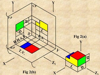
front of V.P, above H.P and inside P.P,
as in fig. 2(b) where the F.V. is
projected on V.P, seen in X direction,
T.V. is projected on H.P, seen in Y
direction & R.H.S.V. is projected on
P.P, seen in Z2 direction
3. It may be noted that :-
a) F.V. (X directional view) is on V.P, T.V. (Y
directional view) is on H.P, while R.H.S.V (Z2
directional view) is on P.P
Fig. 2(c) shows turning of the planes H.P & P.P with
their respective hinges, considering plane V.P as
fixed plane.
b) F.V is within L & H, T.V is within L & D, While
R.H.S.V is within H & D.
c) The symbol for Ist
angle method of projections is
placed as shown on fig. 2(c)
8. FIGURE SHOWS ISOMETRIC VIEW OF A
SIMPLE OBJECT(WITHOUT DIMENSIONS)
SHOW ITS THREE ORTHOGRAPHIC VIEWS
Use First Angle
Method
1. Front View
2. Top View
3. L.H.S.View
A
B
a
b
3
c
2
1
10. FIGURE SHOWS ISOMETRIC VIEW OF AN
OBJECT(WITHOUT DIMENSIONS) SHOW ITS
THREE ORTHO GRAPHIC VIEWS
Use Third
Angle Method
1. Front View
2. Top View
3. L.H.S.View
1. Front View
2. Top View
3. L.H.S.View
A
a
b
3 c
2
1
12. Aim : Figure shows isometric
view, of a simple
machine component.
Draw its following Orthographic
views, & dimension them.
1. Front View
2. Top View
3. R.H.S. View
Use First Angle Method of projection
13. 10
10
Figure, is the isometric view
10
50
75
40
20
R25
30
X
Figure
L = 75+25=100
H = 10+30=40
D=50
17. Figure shows the isometric
view of a vertical shaft support.
Draw its all the three views,
using first angle method of
projections.
Give the necessary dimensions
as per aligned system.
Exercise :-
20. Isometric view of a rod support is
given.
Draw its all the three orthographic
views, using first angle method of
projections.
Give all the dimensions.
Exercise :-Exercise :-