The Mixer Homogeneous Local in Media Device: Detailed Description and its Application to a Plant for the Production of Biogas using Biomass

In various sectors there is a significant need for systems for mixing fluid substances (liquid and/or gaseous) able to accelerate the chemical or physical processes envisaged or simply to homogenize them or keep particles of different densities and phases in suspension with respect to the substrate. The Mixer Homogeneous Local in Media (MHLM) system is a device invented and patented by Stefano Farnè and Vito Lavanga and allows mixing a fluid, increasing its homogeneity and uniformity along surfaces of any profile. The greatest advantage of this device is the possibility of mixing in a localized way and not affecting the entire volume of fluid. It is simple, not bulky and not expensive because it is made up of elements that can be easily found on the market. It essentially consists of two drainage pipes connected by a circulator and uses the hydraulic technique of the "reverse return" in which, thanks to the characteristic arrangement of the pipes, with inlets and outlets placed in a symmetrical and opposite way, it is able to guarantee uniform distribution of loads which facilitates the movement of the fluid and improves its efficiency. The mixing process affected by this device is fundamental in many areas of industry, from agri-food, to the purification of urban wastewater or petroleum processes. In particular, an application of MHLM to an innovative plant for the production of biogas called MBGC will be presented.

Recommended
Recommended
More Related Content
Similar to The Mixer Homogeneous Local in Media Device: Detailed Description and its Application to a Plant for the Production of Biogas using Biomass
Similar to The Mixer Homogeneous Local in Media Device: Detailed Description and its Application to a Plant for the Production of Biogas using Biomass (20)
More from Associate Professor in VSB Coimbatore
More from Associate Professor in VSB Coimbatore (20)
Recently uploaded
Recently uploaded (20)
The Mixer Homogeneous Local in Media Device: Detailed Description and its Application to a Plant for the Production of Biogas using Biomass
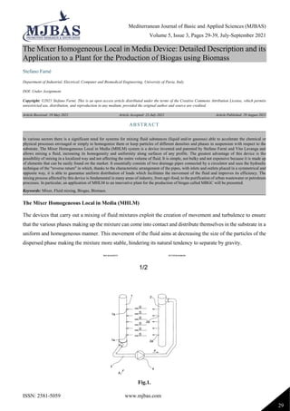
- 1. Mediterranean Journal of Basic and Applied Sciences (MJBAS) Volume 5, Issue 3, Pages 29-39, July-September 2021 ISSN: 2581-5059 www.mjbas.com 29 The Mixer Homogeneous Local in Media Device: Detailed Description and its Application to a Plant for the Production of Biogas using Biomass Stefano Farné Department of Industrial, Electrical, Computer and Biomedical Engineering, University of Pavia, Italy. DOI: Under Assignment Copyright: ©2021 Stefano Farné. This is an open access article distributed under the terms of the Creative Commons Attribution License, which permits unrestricted use, distribution, and reproduction in any medium, provided the original author and source are credited. Article Received: 19 May 2021 Article Accepted: 23 July 2021 Article Published: 29 August 2021 The Mixer Homogeneous Local in Media (MHLM) The devices that carry out a mixing of fluid mixtures exploit the creation of movement and turbulence to ensure that the various phases making up the mixture can come into contact and distribute themselves in the substrate in a uniform and homogeneous manner. This movement of the fluid aims at decreasing the size of the particles of the dispersed phase making the mixture more stable, hindering its natural tendency to separate by gravity. Fig.1. ABSTRACT In various sectors there is a significant need for systems for mixing fluid substances (liquid and/or gaseous) able to accelerate the chemical or physical processes envisaged or simply to homogenize them or keep particles of different densities and phases in suspension with respect to the substrate. The Mixer Homogeneous Local in Media (MHLM) system is a device invented and patented by Stefano Farnè and Vito Lavanga and allows mixing a fluid, increasing its homogeneity and uniformity along surfaces of any profile. The greatest advantage of this device is the possibility of mixing in a localized way and not affecting the entire volume of fluid. It is simple, not bulky and not expensive because it is made up of elements that can be easily found on the market. It essentially consists of two drainage pipes connected by a circulator and uses the hydraulic technique of the "reverse return" in which, thanks to the characteristic arrangement of the pipes, with inlets and outlets placed in a symmetrical and opposite way, it is able to guarantee uniform distribution of loads which facilitates the movement of the fluid and improves its efficiency. The mixing process affected by this device is fundamental in many areas of industry, from agri-food, to the purification of urban wastewater or petroleum processes. In particular, an application of MHLM to an innovative plant for the production of biogas called MBGC will be presented. Keywords: Mixer, Fluid mixing, Biogas, Biomass.
- 2. Mediterranean Journal of Basic and Applied Sciences (MJBAS) Volume 5, Issue 3, Pages 29-39, July-September 2021 ISSN: 2581-5059 www.mjbas.com 30 The MHLM device, presented in the scientific paper of Stefano Farné "Innovative method and device for the homogeneous and delimited mixing of fluids and comparison with currently used systems in the agri-food sector", is described, with reference to Figures 1 and 2: Fig.2. - Figure 1 shows a possible embodiment of the device according to the invention; - Figure 2 shows a variant of the device according to the invention. With reference to figure 1, with (A) it is indicated the device, according to the invention, that includes: • a first manifold (1), preferably tubular, closed at both ends, on which it is made a first plurality of holes (1a) aligned along a generatrix of the first manifold (1); • a second manifold (2), preferably tubular, closed at both ends, on which it is made a second plurality of holes (2a) aligned along a generatrix of the second manifold (2); • a pipe (3) which connects the bottom of the first manifold (1) with the upper part of the second manifold (2); • pumping means (4), inserted in the pipe (3), which cause a movement in the direction indicated by the arrow (F) of the fluid contained in the pipe (3). When the device (A) is submerged in a fluid, liquid or gaseous, the pumping means (4) create a pressure drop inside the first manifold (1) and an overpressure inside the second manifold (2). The consequence is that the fluid, in which the device (A) is submerged, enters the first manifold (1) through the holes (1a), flows through the pipe (3) and exits from the second manifold (2) through the holes (2a). Positioning the first (1) and second (2) manifold so that the first plurality of holes (1a) is faced to the second plurality of holes (2a), it is obtained a flow indicated by the arrows (D), that comes out from the second manifold
- 3. Mediterranean Journal of Basic and Applied Sciences (MJBAS) Volume 5, Issue 3, Pages 29-39, July-September 2021 ISSN: 2581-5059 www.mjbas.com 31 (2) and enters the first manifold (1). In practice, it is obtained a kind of fluid thin layer that exits from the second manifold (2) and enters the first manifold (1). By appropriately sizing the passage sections, i.e. the number and the diameter of the holes (1a) and (2a), and the flow rate of the pumping device (4), it is obtained a laminar motion that does not substantially change the state of motion or the state of rest of the external fluid. However the motion of the thin layer is such as to cause the suction of other material which then enters the first manifold (1) and undergoes a vigorous mixing, due to the passage through the manifolds (1) and (2), the pipe (3) and the pumping device (4). To increase the effectiveness of the mixing, the passage sections can be dimensioned in such a way as to cause accelerations and slowing down of the flow; furthermore the ducts may be internally corrugated to increase the internal turbulence and, therefore, the effectiveness of the mixing. In practice, it is obtained the effect of mixing vigorously the fluid thus perturbing in a minimum extent the movement or the state of rest of the fluid itself, by performing the following steps: • to withdraw a flow of fluid material, using means fitted to carry out the withdrawn fluid without causing disturbances which could change in a substantial way the movement or the state of rest of the fluid of origin; • to make a vigorous mixing of the withdrawn flow; • to reinsert the mixed material into the fluid of origin, using means fitted to carry out said reintroduction without causing disturbances in the fluid which could change in a substantial way the movement or the state of rest This feature makes the device (A) according to the invention, suitable to be inserted into a flow of fluid material in which it is undergoing a reaction (chemical, biological or other) along a given path. The reaction is favoured by an effective mixing of the components that constitute the fluid and the device (A) is suitable to carry out a vigorous mixing, without substantially change the global motion of the fluid itself. Using multiple devices (A) according to the invention and positioning them in sequence along the flow, it is obtained the effect to get an efficient mixing, and therefore a more rapid completion of the reactions in act, without that the flow of fluid materials is changed in a substantial way, as instead it occurs using other devices that carry out the mixing without delimiting the fluid on which they act. The same device (A), according to the invention, is suitable to homogenise locally portions of a fluid mass, without significantly disturb the remaining mass. In fig. 2 it is shown a version (B) of the device according to the invention, in which the position of the collectors is reversed, in such a way that the generatrices along which the holes are aligned (10a), on the first manifold (10), and (20a), on the second manifold (20) are opposite to each other. In this case the device (B) according to this version, achieves the effect of causing a homogeneous flow (D1) in the fluid in which it is inserted. That flow develops in a plane defined by the axis of the manifolds (10, 20) and is oriented according to the direction from the first manifold (10) to the second manifold (20). In the case in which the device (B) is inserted in a pre-existing flow, the flow (D1) is added to the pre-existing flow, whereby there is obtained the effect to increase or reduce the speed of the flow, depending on the mutual orientation of these flows. The fluid to be mixed enters into the holes (10a) of a first manifold (10), flows along a pipe (3a), the pumping device (4) and is reintroduced into the fluid mass through the outlet holes (20a) of a second manifold (20). In practice, if the fluid mass is stationary, the device (B) sets it in
- 4. Mediterranean Journal of Basic and Applied Sciences (MJBAS) Volume 5, Issue 3, Pages 29-39, July-September 2021 ISSN: 2581-5059 www.mjbas.com 32 motion, while if the fluid mass is in motion, the flow (D) is algebraically added to the existing motion of the fluid itself. In both devices (A) and (B), the described configuration of the connection between the first manifold (1, 10) and the second manifold (2, 20) through the pipes (3, 3a) is such as to achieve a condition of reverse return, resulting in the uniform distribution of loads and therefore, uniform advancement of the flow (D, D1). Both the device (A) that the device (B) can be inserted in the fluid by arranging the manifolds (1 , 2, 10, 20) in horizontal or in vertical or in oblique position, above and below the reaction space, helping to counteract the effects of sedimentation or to accentuate specific processes. According to a preferred embodiment, not shown in the figures, the two branches of the circuit, that is the branch in pressure drop, comprising the first manifold (1, 10), and the one under pressure, comprising the second manifold (2, 20) may be conveniently used to change the planes of progression of the fluids. This can be simply obtained by suitably positioning the two manifolds (1, 10) and (2, 20) in such a way that the outgoing flow from the second manifold (2, 20) is not coplanar with the flow entering the first manifold (1, 10). In practice the axis of the first and second manifold (10, 20) are not in the same plane. According to another embodiment, not shown in the figures, the first and second manifold has a curved shape like an open ring. The anaerobic digestion for biogas production Among the renewable sources of energy, there is a growing interest in the exploitation of biomass, as both domestic and agricultural wet waste. This process can be implemented through anaerobic digestion of organic waste, from which various products are obtained, such as water, mineral salts (used as fertilizers) and biogas. In such plants, the homogeneity of the mixture is essential for some of the chemical reactions that occur in the related process. Anaerobic digestion is a biochemical process that occurs in the total absence of oxygen. Some types of microorganisms "demolish" organic substances and produce a gas, called biogas, consisting of 50-70% of methane and the remainder of carbon dioxide. Biogas can be used for the production of electric energy in cogenerators, where the engine exhaust heat is partially used to keep the digester temperature at an ideal level. At the end of the fermentation process, the main nutritional elements already present in the raw material are preserved intact in the substrate, thus favoring the mineralization of organic nitrogen. In this way, the residual digestate is an excellent fertilizer in which nitrogen is in a form that can be directly assimilated by plant organisms. It can also be used to protect soils against erosion. In addition, thanks to anaerobic digestion, a significant reduction in the odor impact is achieved: through measurements it has been noted how the odor can be reduced by up to 80%. Anaerobic digestion also causes the deactivation of various species of seeds, fungi, parasites, viruses and bacteria such as Salmonella, Escherichia coli, Listeria. This makes the use of digestate potentially harmless. In literature and in applications, there are many more or less efficient systems designed for this purpose, most of which require large, expensive and inefficient energy-efficient plant structures. The mini biogas plant in continuous regime (MBGC), illustrated in fig. 3 and presented in the following paragraph, has high energy efficiency and the possible use of the MHLM device contributes to obtaining high energy and environmental yields.
- 5. Mediterranean Journal of Basic and Applied Sciences (MJBAS) Volume 5, Issue 3, Pages 29-39, July-September 2021 ISSN: 2581-5059 www.mjbas.com 33 The Mini BioGas Continuous (MBGC) plant The MBGC (Mini BioGas Continuous), described in the scientific paper by Stefano Farné "Innovative Small Size Plant for the Production of Biogas and Electric Energy from Biomass", is an integrated and above all compact system that can be integrated into small agro-food companies and urban housing settlements. The peculiarity of this plant is that it uses the organic waste of these structures through special hydraulic systems that have the function of withdrawing and entering the waste material into the plant. The main objective of this plant is to recover as much energy as possible from the organic waste material and to reuse the by-product of anaerobic digestion in such a way as to maximize yield. Fig.3. Rendering of the mini-biogas MBGC The tributary, consisting of biomass coming from urban waste or wastewater or from companies in the agro-zootechnical sector or which in any case produce organic wet waste, follows a path inside a suitably sized tank divided into compartments. The organic material is subjected to chemical reactions, different along the path, generating clear haloclines characterizing specific biochemical phases, which leads to the production of the aforementioned products. The insulated container (Fig. 3) is a watertight parallelepiped, internally divided into three macro-volumes by means of two partitions with a height equal to 2/3 of the total height. The first two volumes are placed in communication through a "natural" passage provided by the vertical opening left by the length of the first septum. To connect the second and third volumes, a system is used to filter the compound that has finished the digestion and, at least as regards the energy contribution given by biogas, it can no longer be used. The third volume is divided into three sub-volumes that cover it in width and are kept at an appropriate distance, useful to ensure that different types of salts can be deposited in three different stages. The salts will then be withdrawn by pumps positioned at the corners where presumably the latter will settle. Possible applications of MHLM in the MBGC In some areas of this plant, along the path of the substrate, it is essential to mix the compound so that the tributary is as homogeneous as possible, so that the reactions can be facilitated in their occurrence and can uniformly affect the part of the volume subjected to such transformations. Furthermore, since the flow of the liquid in the tank is
- 6. Mediterranean Journal of Basic and Applied Sciences (MJBAS) Volume 5, Issue 3, Pages 29-39, July-September 2021 ISSN: 2581-5059 www.mjbas.com 34 continuous, there is no physical separation between one digestion stage and the other, characterized only by specific haloclines that allow specific actions, so it is important that mixing takes place only for a portion of digested without altering the subsequent portions, already ahead with the digestion process, or with the previous portions, engaged in other chemical-physical transformations. In this context, the MHLM mixer object of this paper finds an adequate application. More specifically, MHLM could find an excellent use in the first part of the tank, an area where the biomass and water necessary for the anaerobic digestion process takes place, and where it is necessary to create uniformity of concentration of the various substances present in the waste so that the chemical reactions determining the first phase, called hydrolytic, can take place homogeneously in the specific volume in which they are foreseen. Another position in which MHLM could find useful, is in the transition part from the first to the second volume in which, through an optical fiber device, an attempt is made to reduce the amount of hydrogen sulphide, harmful if it reaches internal combustion motors and if present in large quantities. The purpose for which MHLM was designed is ideal for responding to the need to mix the wastewater introduced into the separator to make it homogeneous within the occupied volume. The correct operation of the MBGC digester implies that the percentage of total substrate solids is about 10% (WET = 10% means that the circulating matrix has 90% of water and 10% of ST (total solids); the substrate is composed of 20% ash and 80% of SV (volatile solids): this implies that the incoming substrate is mixed with an ideal quantity of water to obtain the desired result. It is therefore evident the need to mix the quantity introduced making it uniform. Consider the following numerical example: for the injection, 1000 liters of wastewater are taken from the previous storage tank (Imhoff of first delivery from the waste systems) of which 20% of total solids, divided into 700 liters of protein fraction taken from the lower part and 300 liters of oleic fraction taken from the upper part of the Imhoff tank; this quantity is sent via a pipeline to the entrance of the MBGC; here the wastewater is released vertically and along the generatrix of the tube, where it begins to impress the laminar motion, then supported by the predefined geometric structure. Being in the regime of communicating vessels, if there is a hydrostatic pressure at the entrance to the tank then it (based on the volume and the wet perimeter) will tend to expel what is at the end of the same. At half height of the liquid phase in the third volume 1000 liters will be expelled. To maximize the performance, all that part not completely digested will be recirculated, creating an internal recirculation. Based on the results of a BMP test (test that evaluates the methane potential of a certain matrix), about 80% of the mass will have been digested after 10 days. On the tenth day of the process, about 100 liters from the bottom and 100 liters from the top will be taken from the end of the second volume, where there are protein fractions and oleic fractions, respectively, then taken in equal measure, together with 800 liters from the bottom of the third volume. To make the volumes deriving from the internal recirculation as homogeneous as possible with the incoming mass, the latter will be introduced in the middle of the incoming volume (which will occupy the first about 1.5 m, of the total about 3 m) and about 0.8 m from the start (both the 100 + 100 liters of V2 and the 800 liters of V3). To maximize the mixing of the substrate, they can be made further homogeneous, in the first three meters of the path, by means of an MHLM mixer, with the drainage pipes arranged vertically at 0.1 m and 2.9 m. After the first part of the daily process, to facilitate the settling of concentrations, the part of the daily heating process will begin
- 7. Mediterranean Journal of Basic and Applied Sciences (MJBAS) Volume 5, Issue 3, Pages 29-39, July-September 2021 ISSN: 2581-5059 www.mjbas.com 35 at the same time as that of mixing. This process will take place for about 15 minutes a day and the heating temperature will be around 50 °C, guaranteed by a heat exchanger allocated in this first part of the process. So, considering that the device will have to treat a volume of 2000 liters (2 m3 ), 1000 liters of injection and 1000 liters of internal recirculation, in a time of about 15 minutes, the flow rate to be guaranteed by the circulation pump can be calculated by the following formula: The flow rate calculated with the project data is 16 times higher than that required if the entire volume is treated in 15 minutes, ensuring that the volume is treated several times by the mixer, increasing the efficiency of the process. An additional MHLM mixer can be arranged in the curved section between the first and second volume (Fig. 4). Here the passage of the substrate takes place, in a laminar way, in the second volume in which the chemical reactions vary, from hydrolytic and acid of the first septum, to acid and methanogen, and in which the oleic, protein and compound part will be divided in mineral salts and water. It is therefore important that in the transition section between these two volumes a mixing action is carried out so that the substrate coming from the previous section is uniform and homogeneous to facilitate the action of the bacteria present in this section. Furthermore, in this transition zone there may be a system that dissolves the hydrogen sulphide (H2S), in nitrogenous compounds or similar acids, through a desulphurization action that can take place in different ways (for e.g., with action of light emitted by optical fibers that generate anoxygenic photosynthesis) but always with need to homogenize the fluid. Fig.4. Rendering of the MBGC system with two MHLM mixers To ensure uniform mixing and considering that it must be guaranteed along a curved surface, MLHM must consist of curved drainage pipes facing the desired mixing profile, as illustrated in Fig. 5. Fig.5. MHLM in trim for curved mixed surface profile
- 8. Mediterranean Journal of Basic and Applied Sciences (MJBAS) Volume 5, Issue 3, Pages 29-39, July-September 2021 ISSN: 2581-5059 www.mjbas.com 36 The MBGC digester can also be made in a circular shape with concentric dividers. It would emulate the linear dynamics of the MBGC digester presented above, but with concentric phases. It could be realized in large plants of about 3000 m3 with radii of about 16 meters and height of the septa of 6 or 7 m. The release would take place in the central area and then flow in a radial direction as the chemical reactions involved, hydrolytic, acidic, acetic and methanogenic, vary. At this point the fluid will have reached the internal cylinder. Here, through the hydrostatic thrust coming from the daily intake, they would enter the outermost cylinder to initiate a circular motion along the circumference, emulating the third phase of MBGC with linear dynamics, to separate the salts. This path is also improved with respect to the linear arrangement given the greater path taken by the fluid. In this context, the versatility of the MHLM mixer could be further exploited, which could in any case guarantee a homogeneous mixing of the substrate by arranging the drainage pipes in a circular shape. Four MHLM mixers are arranged in a circular configuration with increasingly larger diameters of the draining pipes, assuming to insert each one in the middle of the phase concerned, among those mentioned above. This greatly enhances the fundamental advantage characterizing MHLM of being able to mix volume portions in a larger volume only through the particular arrangement of the tubes. The image in Fig. 6 shows a rendering of the device in this setting. Fig.6. MHLM in trim for circular mixed profile Fig.7. Pseudo-MHLM rendering for oleic and protein phase recirculation Fig.8. Pseudo-MHLM rendering for intermediate phase introduction in the outermost cylinder for gravimetric salt separation
- 9. Mediterranean Journal of Basic and Applied Sciences (MJBAS) Volume 5, Issue 3, Pages 29-39, July-September 2021 ISSN: 2581-5059 www.mjbas.com 37 Pseudo-MHLM have also been inserted (Fig. 7 and Fig. 8) through which to carry out the recirculation action of the protein and oleic phase, coming from the end of the methane phase and therefore at the limits of the internal cylinder, together with the water taken from the end of the phase of separation of the salts, reintroduced at the entrance. Furthermore, one of these is responsible for allowing the transition from the internal to the external cylinder of the medium density phase composed of water, salts and ash. The result is therefore an articulated system that could significantly increase efficiency thanks to the use of MHLM (Fig. 9 and Fig. 10). Therefore, the great versatility of MHLM is evident that through the variation of the shape of the drainage pipes it is possible to achieve a multitude of surfaces mixed with the most disparate profiles (circular, segmented, sinusoid, etc.) and which affect only a specific portion of the volume available. Fig.11. Dynamic paddle mixer Dynamic blading mixers are normally used to mix in anaerobic digesters, as presented in the scientific paper of Stefano Farné "Innovative Method and Device for the Homogeneous and Delimited Mixing of Fluids and Comparison with Currently Used Systems in the Agri-Food Sector". An example of these devices can be the mixer (Fig. 11) to homogenize the fluids of an anaerobic digester. It is a dynamic blading mixer with a sturdy frame to resist vibration and that supports both side and ceiling mounting. It is driven by a three-phase motor, which can be 15 kW / 4 poles or 18.5 kW / 4 poles at 50 Hz. All parts in contact with the substrate are made of stainless steel. The blading has a diameter of 600 mm and rotates at 500 rpm, with the motor at 1450 rpm reduced by a belt reduction. Fig.9. Circular MBGC rendering with MHLM and pseudo MHLM mixers Fig.10. Top view of circular MBGC
- 10. Mediterranean Journal of Basic and Applied Sciences (MJBAS) Volume 5, Issue 3, Pages 29-39, July-September 2021 ISSN: 2581-5059 www.mjbas.com 38 It has limitations on the part of the mixed volume, which is not easily controllable as the mixing depth is fixed with the choice of the mounting depth, possibly modifiable through the inclination of the shaft. Furthermore, its efficiency is related to the shape of the tank in which it is mounted and has a bulky and fragile architecture, given the transmission shaft is in an oil bath. Other mixers suitable for anaerobic digesters use a vertical rod on which they are mounted and can slide by mixing at different depths. Although more advantageous thanks to the sliding on the rod, the excessive bulk and low mixing efficiency remain evident, higher near the blades and significantly lower moving away from them. In fact, they carry out a mixing which, albeit limited thanks to the design choices, involves a volume of substrate which, for example in the case of MBGC, could decrease its efficiency given the involvement of volumes in different stages of anaerobic transformation. The advantages of the MHLM mixer are therefore evident. In fact, it guarantees localized mixing by creating surfaces with a desired profile of mixed substrate, requiring a very low energy input, necessary only for handling the pump, and less time for the mixing to be satisfactory and uniform. Conclusions MHLM is a very versatile device and its use can be advantageous in many industrial fields such as the food industry, for example in the production of yogurt, to homogenize the product and the reactions inside it, or in the production of beer to standardize the fermentation of the malt and for the following functions: • to support the delimited mixing level to hydrolytic portion in the anaerobic digestion; • to support a gentle excitation to avoid sedimentation phenomena (e.g. microalgae); • in wastewater conditioners where it is necessary to set in motion a delimited zone and to leave stationary the others. It can be used in both small and large plants and requires minimal maintenance. It is achievable with a low construction cost, given the materials that can be easily purchased on the market, but also a low cost of use. MHLM above all has the great advantage of being able to mix only a portion of a given volume, as is very evident by observing the use of this mixer in the MBGC anaerobic digester. It facilitates the carrying out of different biochemical reactions in different areas of the reactor without one phase of the process affecting or contaminating the other thanks to the creation of desired mixed surfaces. Future studies may highlight further applications and benefits of MHLM. Patent LAVANGA, Vito - FARNE', Stefano Method and device for the homogeneous and delimited mixing of fluids – MHLM (https://patentscope.wipo.int/search/en/detail.jsf?docId=WO2016092579). Declarations Source of Funding This research did not receive any grant from funding agencies in the public, commercial, or not-for-profit sectors.
- 11. Mediterranean Journal of Basic and Applied Sciences (MJBAS) Volume 5, Issue 3, Pages 29-39, July-September 2021 ISSN: 2581-5059 www.mjbas.com 39 Competing Interests Statement The author declares no competing financial, professional and personal interests. Ethical Approval Based on Institutional guidelines. Consent for publication Author declares that he consented for the publication of this research work. Bibliography Ahmed T., Makwashi N., Hameed M., A Review of Gravity Three - Phase Separators, Journal of Emerging Trends in Engineering and Applied Sciences, 2017. Baker J.R., Motionless mixers stir up new uses. Chem. Eng. Prog., 87, 32–38, 1991. Batchelor, G.K., The theory of Homogeneous Turbulence, Cambridge University Press, England, 1953. Edward L. Paul, Victor A. Atiemo-Obeng, Suzanne M. Kresta- Handbook of industrial mixing - Science and practice, cap. 21-Mechanical Design of Mixing Equipment, 2004. Elhaj, M. E. M., & Adli, M. G. A. (2014). Influence of flow characteristics on the design of two-phase horizontal separators. Journal of Science and Technology 15, 2014. Farné S., Innovative Method and Device for the Homogeneous and Delimited Mixing of Fluids and Comparison with Currently Used Systems in the Agri-Food Sector, Mediterranean Journal of Basic and Applied Sciences, Volume 5, Issue 2, Pages 90-107, April-June 2021. Farné S., Innovative Small Size Plant for the Production of Biogas and Electric Energy from Biomass, Middle East Journal of Applied Science & Technology, Vol.3, Iss.3, Pages 09-27, July-September 2020. Farné S., Macchine. Macchine idrauliche. Synopsis, Libreria Universitaria Medea. Ghanem A., Lemenand T., Della Valle D., Peerhossaini H., Static mixers: Mechanisms, applications, and characterization methods – A review, Chemical Engineering Research and Design 92, 2014, 205–228. Mostafaiyan M., Mohammad Reza Saeb, Alireza Emami Alorizi, Maysam Farahani, Application of evolutionary computational approach in design of horizontal three-phase gravity separators, J. of Petr. Sci. and Engg., 2014. Stewart M., Arnold K., Gas Liquid and Liquid-Liquid Separators, Gulf Professional Printing, Elsevier Inc., 2008.