Paper based reconfigurable flow switch for paper microfluidics

We attempt to offer an innovative solution to the issues of long response times, large volumes of actuation fluid, and external control circuitry that have been associated with past approaches in creating switches in paper microfluidics. Our method consists of a device created from chromatography paper and featuring folds which, when selectively wetted with an actuation fluid, will either raise or lower the actuator's tip and thus engage or break the desired fluidic connections. As a result, response time is drastically reduced (2 seconds) and the volume of actuation fluid consumed is extremely small (4 microliters). We have tested this approach with six switch configurations, ranging from single-pole single-throw (normally OFF and normally ON) to single-pole double-throw (with single and double break). We further demonstrate its potential with a colorimetric assay involving six actuators in parallel, which can detect the presence of three analytes (glucose, protein, and nitrite) in artificial saliva. Finally, this work brings in the concept of origami to paper microfluidics, combining multiple-fold geometries for programmable switching of fluidic connections. "A fast, reconfigurable flow switch for paper microfluidics based on selective wetting of folded paper actuator strips", Lab on Chip, 2017, 17, 3621

Recommended
Recommended
More Related Content
Similar to Paper based reconfigurable flow switch for paper microfluidics
Similar to Paper based reconfigurable flow switch for paper microfluidics (20)
More from Iowa State University
More from Iowa State University (20)
Recently uploaded
Recently uploaded (20)
Paper based reconfigurable flow switch for paper microfluidics
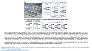
- 1. Kong, T., Flanigan, S., Weinstein, M., Kalwa, U., Legner, C., & Pandey, S. (2017). A fast, reconfigurable flow switch for paper microfluidics based on selective wetting of folded paper actuator strips. Lab on a Chip, 17(21), 3621–3633. https://doi.org/10.1039/C7LC00620A https://pubs.rsc.org/en/content/articlelanding/2017/LC/C7LC00620A Fig. 1 All-paper actuator is presented where physical connection from the input channel to multiple output channels is established by activating the actuator. Water is added either directly on the folds or through a delay time strip to lift (or lower) the actuator tip. (a) CAD model of the actuator-controlled fluid flow is shown. Three actuators are activated by wetting their respective folds through a delay time strip. The output channels contain dried reagents to test the presence of glucose, protein, and nitrite in the test fluid applied at the port of the input channel. Upon activating the actuators, test fluid flows into the three output channels, and a color change occurs in the three output channels indicating the presence of the analytes. (b) Schematic of the single-pole single-throw (SPST) switch is shown. In the ‘normally OFF’ configuration, the output channel is initially separated by a vertical distance from the input channel and there is no fluid flow to the output channel. Upon activating the ac- tuator, the input channel makes contact with the output channel and fluid flow is established. In the ‘normally ON’ configuration, both the input and output channels are in contact. Upon activating the actuator, the input channel is lifted and fluid flow is blocked to the output channel. (c) Schematic of the single-pole double-throw (SPDT), single-break switch is shown. Fluid flow from one input channel to two output channels is controlled by the actuator. The ‘normally OFF’ and ‘normally ON’ switches are combined together and the vertical position of the actuator tip is controlled by wetting the crest and/or trough of the actuator's fold. (d) Schematic of the single-pole double-throw (SPDT), double-break switch is shown. Fluid flow from two input channels to two output channels is controlled by the actuator. Fluidic connections to the two contacts are inde- pendently established by activating the crests and troughs of the actuator's fold.
- 2. Fig. 2 Proposed actuation model to estimate the actuation height achieved by wetting the fold. (a) Initial position of the single-fold actuator is il- lustrated. The crest and the two troughs are labelled. The left trough is taped and rest of the paper is free to move. The length of each side is L. The initial fold angle at the crest is 2θ. (b) After crest activation, the fold angle at the crest relaxes to 2α and the right trough is raised to a height ‘hC’. (c) After activating the left trough, the initial fold angle at this trough (i.e. 90° + θ) relaxes to β and the right trough is lowered to a height ‘hT’. The expressions for the height raised (hC) and lowered (hT) are given by eqn (1) and (2), respectively. Kong, T., Flanigan, S., Weinstein, M., Kalwa, U., Legner, C., & Pandey, S. (2017). A fast, reconfigurable flow switch for paper microfluidics based on selective wetting of folded paper actuator strips. Lab on a Chip, 17(21), 3621–3633. https://doi.org/10.1039/C7LC00620A https://pubs.rsc.org/en/content/articlelanding/2017/LC/C7LC00620A
- 3. Fig. 3 Single-pole single-throw (SPST) ‘normally OFF’ switch. (a) CAD model (i) and actual image (ii) of the ‘normally OFF’ switch are shown. The input channel is separated by a vertical distance (2 mm) from the output channel. An actuator with a single fold is placed such that its tip is posi- tioned vertically below the edge of the input channel. (b and c) Figures in panel (b) and panel (c) show the device in CAD model and actual experi- ment, respectively. Blue-colored water is dropped on the port of the input channel that eventually saturates it (b-i and c-i). No fluid flow is permit- ted in the output channel because of its physical separation from the input channel. Red-colored water is then dropped on the crest of the actuator's fold that raises the tip and brings the input channel in contact with the output channel (b-ii and c-ii). The blue-colored water now flows into the output channel (b-iii and c-iii). (d) Flow rate of the fluid front is plotted in the input channel before actuation and in the output channel af- ter crest actuation. Kong, T., Flanigan, S., Weinstein, M., Kalwa, U., Legner, C., & Pandey, S. (2017). A fast, reconfigurable flow switch for paper microfluidics based on selective wetting of folded paper actuator strips. Lab on a Chip, 17(21), 3621–3633. https://doi.org/10.1039/C7LC00620A https://pubs.rsc.org/en/content/articlelanding/2017/LC/C7LC00620A
- 4. Fig. 4 Single-pole single-throw (SPST) ‘normally ON’ switch. (a) CAD model (i) and actual image (ii) of the switch are shown. Initially, the input channel is in contact with the output channel and fluid flow occurs between the two channels. An actuator with a single fold is placed such that its tip is positioned vertically below the input channel. (b and c) Figures in panel (b) and panel (c) show the device in CAD model and actual experi- ment, respectively. Blue-colored water is dropped on the port of the input channel that eventually saturates it (b-i and c-i). Fluid flow is permitted to the output channel (b-ii and c-ii). Red-colored water is then dropped on the crest of the actuator's fold that raises the tip of the actuator and lifts the input channel to physically separate from the output channel. (b-iii and c-iii). (d) Flow rate of the fluid front is plotted in the input and out- put channels before actuation and in the output channel after crest actuation. Kong, T., Flanigan, S., Weinstein, M., Kalwa, U., Legner, C., & Pandey, S. (2017). A fast, reconfigurable flow switch for paper microfluidics based on selective wetting of folded paper actuator strips. Lab on a Chip, 17(21), 3621–3633. https://doi.org/10.1039/C7LC00620A https://pubs.rsc.org/en/content/articlelanding/2017/LC/C7LC00620A
- 5. Fig. 5 Single-pole double-throw (SPDT), single-break switch with crest actuation. (a) CAD model (i) and actual image (ii) of the switch are shown. Initially, the input channel is in contact with output channel 1 while output channel 2 is vertically separated from them. An actuator with a single fold is placed such that its tip is positioned vertically below the input channel. (b and c) Figures in panel (b) and panel (c) show the device in CAD model and actual experiment, respectively. Blue-colored water is dropped on the port of the input channel that eventually saturates it and flow is permitted to output channel 1 (b-i and c-i). Red-colored water is then dropped on the crest of the actuator's fold that raises the actuator tip and lifts the input channel to physically separate from output channel 1 and touch output channel 2 (b-ii and c-ii). Fluid flow is now established in out- put channel 2 (b-iii and c-iii). (d) Flow rate of the fluid front is plotted in the input and output channel 1 before actuation and in the output channel 2 after crest actuation. Kong, T., Flanigan, S., Weinstein, M., Kalwa, U., Legner, C., & Pandey, S. (2017). A fast, reconfigurable flow switch for paper microfluidics based on selective wetting of folded paper actuator strips. Lab on a Chip, 17(21), 3621–3633. https://doi.org/10.1039/C7LC00620A https://pubs.rsc.org/en/content/articlelanding/2017/LC/C7LC00620A
- 6. Fig. 6 Single-pole double-throw (SPDT), single-break switch with crest and trough actuation. (a) CAD model (i) and actual image (ii) of the switch are shown. Initially, the input channel is placed in between the two output channels and vertically separated from them. An actuator with a single fold is placed such that its tip is positioned vertically below the input channel. (b and c) Figures in panel (b) and panel (c) show the device in CAD model and actual experiment, respectively. Blue-colored water is dropped on the port of the input channel that eventually saturates it (b-i and c-i). No fluid flow is permitted in the two output channels because of their physical separation from the input channel. Red-colored water is then dropped on the crest of the actuator's fold that raises its tip and brings the input channel in contact with output channel 1 and the blue-colored water now flows into this output channel (b-ii and c-ii). Another round of red-colored water is dropped near the trough of the actuator's fold that lowers the actuator tip and brings the input channel in contact with output channel 2 (b-iii and c-iii). (d) Flow rate of the fluid front is plotted in the input channel before actuation, in output channel 1 after crest actuation, and in output channel 2 after trough actuation. Kong, T., Flanigan, S., Weinstein, M., Kalwa, U., Legner, C., & Pandey, S. (2017). A fast, reconfigurable flow switch for paper microfluidics based on selective wetting of folded paper actuator strips. Lab on a Chip, 17(21), 3621–3633. https://doi.org/10.1039/C7LC00620A https://pubs.rsc.org/en/content/articlelanding/2017/LC/C7LC00620A
- 7. Fig. 7 Single-pole double-throw (SPDT), single-break switch with ac- tuation of two crests. (a and b) Figures in panel (a) and panel (b) depict the device in CAD model and actual experiment, respectively. Initially, the input channel touches output channel 1 but is vertically separated from output channel 2. An actuator with two folds is placed such that its tip is positioned vertically below the input channel. Blue-colored water is dropped on the port of the input channel that eventually satu- rates it and flow is permitted to output channel 1 (a-i and b-i). Red- colored water is then dropped on the crest of the actuator's left fold that raises the actuator tip and lifts the input channel to physically sep- arate from output channel 1 (a-ii and b-ii). Another round of red- colored water is dropped on the crest of the actuator's right fold that brings the input channel in contact with output channel 2 (a-iii and b- iii). Fluid flow is now established into output channel 2 (a-iv and b-iv). Kong, T., Flanigan, S., Weinstein, M., Kalwa, U., Legner, C., & Pandey, S. (2017). A fast, reconfigurable flow switch for paper microfluidics based on selective wetting of folded paper actuator strips. Lab on a Chip, 17(21), 3621–3633. https://doi.org/10.1039/C7LC00620A https://pubs.rsc.org/en/content/articlelanding/2017/LC/C7LC00620A
- 8. Fig. 8 Single-pole double-throw (SPDT), double-break switch to con- trol two pairs of input and output channels. (a and b) Figures in panel (a) and panel (b) depict the device in CAD model and actual experi- ment, respectively. Initially, two input channels are placed vertically above their respective output channels but are vertically separated from their output channels. An actuator with two folds is placed such that its tip is positioned vertically below the left input channel. Blue- colored and green-colored water are dropped on the ports of the two input channels which eventually saturate them. Fluid flow is blocked to the output channels (a-i and b-i). Red-colored water is then dropped on the crest of the actuator's left fold that raises the actuator tip and lifts the (left) input channel to touch the (left) output channel (a-ii and b-ii). Another round of red-colored water is dropped on the trough of the actuator's left fold that lowers the tip and removes the previously established connection (a-iii and b-iii). Final round of red-colored wa- ter dropped on the crest of the actuator's right fold brings the (right) input channel in contact with the (right) output channel (a-iv and b-iv). Kong, T., Flanigan, S., Weinstein, M., Kalwa, U., Legner, C., & Pandey, S. (2017). A fast, reconfigurable flow switch for paper microfluidics based on selective wetting of folded paper actuator strips. Lab on a Chip, 17(21), 3621–3633. https://doi.org/10.1039/C7LC00620A https://pubs.rsc.org/en/content/articlelanding/2017/LC/C7LC00620A
- 9. Fig. 9 Colorimetric assay for the simultaneous detection of glucose, protein, and nitrite from artificial saliva. (a) The two-part mold design for the enclosure setup consists of a base and a cover. The base contains slots to place the two input channels, six output channels, six actuators, and two delay timer strips. The cover contains inlets to drop the test and control samples, three reagents, and actuation fluid. The output channels are wicked with the three reagents and dried at room temperature. The channels, actuators, and delay timer strips are taped in their respective slots. (b) Artificial saliva spiked with analytes is dropped on the experimental port while unspiked artificial saliva is used at the control port. By wicking, fluid flows and saturates the two input channels. (c) After a pre-defined delay, distilled water is dropped on the delay time strips. As water travels through a timer strip, the crests of three actuators are activated to raise their respective tips. Thereafter, the experimental fluid flows into the bot- tom three output channels while the control fluid flows into the top three output channels. (d) A positive color change is confirmed for the experi- mental case indicating the presence of glucose, protein, and nitrite. A negative color change is shown in the control case. Kong, T., Flanigan, S., Weinstein, M., Kalwa, U., Legner, C., & Pandey, S. (2017). A fast, reconfigurable flow switch for paper microfluidics based on selective wetting of folded paper actuator strips. Lab on a Chip, 17(21), 3621–3633. https://doi.org/10.1039/C7LC00620A https://pubs.rsc.org/en/content/articlelanding/2017/LC/C7LC00620A