
Recommended
Recommended
More Related Content
What's hot
What's hot (20)
Similar to "Pavement failures and their Maintenance" Technical Seminar report
Similar to "Pavement failures and their Maintenance" Technical Seminar report (20)
Recently uploaded
Recently uploaded (20)
"Pavement failures and their Maintenance" Technical Seminar report
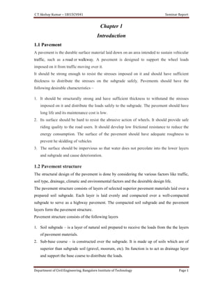
- 1. C T Akshay Kumar – 1BI15CV041 Seminar Report Department of Civil Engineering, Bangalore Institute of Technology Page 1 Chapter 1 Introduction 1.1 Pavement A pavement is the durable surface material laid down on an area intended to sustain vehicular traffic, such as a road or walkway. A pavement is designed to support the wheel loads imposed on it from traffic moving over it. It should be strong enough to resist the stresses imposed on it and should have sufficient thickness to distribute the stresses on the subgrade safely. Pavements should have the following desirable characteristics – 1. It should be structurally strong and have sufficient thickness to withstand the stresses imposed on it and distribute the loads safely to the subgrade. The pavement should have long life and its maintenance cost is low. 2. Its surface should be hard to resist the abrasive action of wheels. It should provide safe riding quality to the road users. It should develop low frictional resistance to reduce the energy consumption. The surface of the pavement should have adequate roughness to prevent he skidding of vehicles 3. The surface should be impervious so that water does not percolate into the lower layers and subgrade and cause deterioration. 1.2 Pavement structure The structural design of the pavement is done by considering the various factors like traffic, soil type, drainage, climatic and environmental factors and the desirable design life. The pavement structure consists of layers of selected superior pavement materials laid over a prepared soil subgrade. Each layer is laid evenly and compacted over a well-compacted subgrade to serve as a highway pavement. The compacted soil subgrade and the pavement layers form the pavement structure. Pavement structure consists of the following layers 1. Soil subgrade – is a layer of natural soil prepared to receive the loads from the the layers of pavement materials. 2. Sub-base course – is constructed over the subgrade. It is made up of soils which are of superior than subgrade soil (gravel, moorum, etc). Its function is to act as drainage layer and support the base coarse to distribute the loads.
- 2. C T Akshay Kumar – 1BI15CV041 Department of Civil Engineering, Bangalore Institute of 3. Base course – is constructed over sub It is the structural member of the pavement and helps in distributing the wheel 4. Surface course – is the topmost layer. It is made up of superior quality aggregates and binder to resist abrasive action of traffic, prevent percolation of water into the pavement and provide skid resistant, smooth and uniform driving surface. 1.3 Types of pavement 1. Flexible pavements – are those which have a low or negligible flexural strength and flexible in their structural action of loads. pavements. 2. Rigid pavements – are those which possess high flexural strength. They are also called as Cement Concrete pavements. Fig 1.2 Cross section of Flexible and Rigid Pavement 1BI15CV041 Seminar Report Department of Civil Engineering, Bangalore Institute of Technology is constructed over sub-base and is made up of crushed stones with binder. It is the structural member of the pavement and helps in distributing the wheel is the topmost layer. It is made up of superior quality aggregates and binder to resist abrasive action of traffic, prevent percolation of water into the pavement and provide skid resistant, smooth and uniform driving surface. Fig 1.1 – Pavement structure are those which have a low or negligible flexural strength and flexible in their structural action of loads. They are also called as Bituminous Concrete are those which possess high flexural strength. They are also called as Cement Concrete pavements. Fig 1.2 Cross section of Flexible and Rigid Pavement Seminar Report Page 2 base and is made up of crushed stones with binder. It is the structural member of the pavement and helps in distributing the wheel loads. is the topmost layer. It is made up of superior quality aggregates and binder to resist abrasive action of traffic, prevent percolation of water into the pavement are those which have a low or negligible flexural strength and They are also called as Bituminous Concrete are those which possess high flexural strength. They are also called as
- 3. C T Akshay Kumar – 1BI15CV041 Seminar Report Department of Civil Engineering, Bangalore Institute of Technology Page 3 Table 1.1 – Differences between Flexible and Rigid pavement Sl.No. Flexible Pavement Rigid Pavement 1. A flexible pavement consists of a thin wearing course built over a base course and sub-base course resting upon o compacted subgrade. A rigid pavement consists of a cement concrete slab (Pavement quality concrete over Dry Lean Concrete) built over sub- base course and subgrade. 2. It has negligible or low flexural strength. It has high flexural strength compared to flexible pavement. 3. The load distribution is by grain to grain contact. The load distribution is by beam action. 4. Its stability depends upon aggregate interlock, friction and cohesion. Its stability is provided by pavement slab by beam action. 5. Its design depends upon the strength of subgrade. Its design depends upon the flexural strength of concrete. 6. Design life is 10 – 15 years. Design life is 30 – 40 years. 7. Initial cost of construction is less but maintenance is regular and costly. Initial cost of construction is high but maintenance cost is less. 8. It is suited for staged construction. It can be opened to traffic immediately after construction. It is not suited for staged construction. It requires 28 days of curing before opening to the traffic. 1.4 Types of pavement failures 1. Cracking 2. Potholes 3. Rutting 4. Shoving 5. Raveling 6. Bleeding
- 4. C T Akshay Kumar – 1BI15CV041 Seminar Report Department of Civil Engineering, Bangalore Institute of Technology Page 4 Chapter 2 Cracking Cracking occurring in flexible pavements can be classified into three types, i.e. surface cracks, fatigue cracks and others. Surfacing cracks are associated with the aging and deterioration of the surface bituminous layer due to shrinking and hardening of the bituminous binder with a loss of volatiles. These cracks are in general not load- related. Fatigue cracks (commonly called alligator or crocodile cracks) are a series of interconnected cracks in a chicken-wire pattern. The cracks are caused by traffic loading, occur only in wheel-paths and are often associated with deformation. Early signs of fatigue cracks are fine parallel longitudinal cracks in the wheel-path. Other types of cracks in flexible pavements are longitudinal, edge, transverse, reflection and stabilization cracks. 2.1 Types of Cracking 1. Alligator cracking 2. Block cracking 3. Longitudinal cracking 4. Transverse cracking 5. Reflection cracking 2.2 Alligator cracking Alligator cracks are also called as map cracking or crocodile cracking. This is a fatigue failure caused in the asphalt concrete. A series of interconnected cracks are observed due to such distress. Repeated loading and stress concentration will help the individual cracks to get connected. This looks like a chicken wire or similar to the alligator skin. This cracking is load associated structural failure. This cracking is observed in areas that have repeated traffic loading. Alligator cracking is one of the major structural distress. This distress is later accompanied by rutting. The failure can be due to weakness in the surface, base or sub grade; a surface or base that is too thin; poor drainage or the combination of all three.
- 5. C T Akshay Kumar – 1BI15CV041 Seminar Report Department of Civil Engineering, Bangalore Institute of Technology Page 5 Fig 2.1 Alligator cracking 2.3 Block cracking It is caused mainly due to the shrinkage of the asphalt pavement due to inability of the binder to expand and contract with temperature changes. It is also called as thermal cracking. It is not load associated, but loads can increase the severity of cracks. Block cracking has cracks in well-defined rectangular shapes. Block cracks divide the asphalt surface into approximately rectangular pieces. The blocks range in size from approximately 0.1 to 10m². The occurrence of block cracking usually indicates that the asphalt has hardened significantly. Block cracking normally occurs over a large portion of pavement area, but sometimes will occur only in non-traffic areas. Fig 2.2 Block cracking
- 6. C T Akshay Kumar – 1BI15CV041 Seminar Report Department of Civil Engineering, Bangalore Institute of Technology Page 6 2.3 Longitudinal and Transverse cracking These are cracks are parallel to the pavement centerline. They are caused by shrinkage of asphalt surface due to low temperature. These can be a result of pavement fatigue, reflective cracking, or poor joint construction. Fig 2.3 Longitudinal cracking Fig 2.4 Transverse cracking 2.4 Reflection cracking It is caused by differential movement across the underlying crack or joint. These cracks are found in flexible pavement overlay over a rigid pavement (i.e., asphalt over concrete). They occur directly over the underlying rigid pavement joints. Fig 2.5 Reflection cracking
- 7. C T Akshay Kumar – 1BI15CV041 Seminar Report Department of Civil Engineering, Bangalore Institute of Technology Page 7 2.6 Remedial measures for Cracking 1. A thin (150 to 300 mm) strip of geo-textile can be applied on the crack. 2. Cracking can be sealed by application of a membrane of Polymer modified bitumen (PMB). 3. Less sever surface cracking can be addressed with the application of a rejuvenator to the surface. 4. Extensive and severe surface cracking can be rectified by removal and replacement of the defective portion of the layer. A tack coat and a new layer of bituminous concrete is applied and well compacted. Fig 2.6 Repairing cracks
- 8. C T Akshay Kumar – 1BI15CV041 Department of Civil Engineering, Bangalore Institute of Potholes are small, bowl-shaped depressions developed on the surface of the flexible pavement. They generally have sharp edges and vertical sides near the top of the hole. penetrate all the way through the asphalt layer down to the base course. Pothol result of moisture infiltration, stagnation of water and usually the end result of untreated alligator cracking. As alligator cracking becomes severe, the interconnected cracks create small chunks of pavement, which can be dislodged as vehicles remaining hole after the pavement chunk is dislodged is called a pothole. fatigue is the main reason behind the formation of potholes. The occurrence of fatigue cracking will interlock to form alligator cracking. These chu the pavement will become loose and will be picked out under continuous loading and stresses. This will leave a pothole on the pavement. Fig 3.1 Formation of Pothole In cold temperatures, the water trapped in the pothole action that leads to additional stresses and crack propagation. distress grows resulting in the continuous removal of pavement chunks. Water entrapped will increase this rate of expansion of distress. The pothole can expand to several feet in width. They don’t develop too much in depth. The vehicle tires 1BI15CV041 Seminar Report Department of Civil Engineering, Bangalore Institute of Technology Chapter 3 Potholes shaped depressions developed on the surface of the flexible They generally have sharp edges and vertical sides near the top of the hole. penetrate all the way through the asphalt layer down to the base course. Pothol result of moisture infiltration, stagnation of water and usually the end result of untreated alligator cracking. As alligator cracking becomes severe, the interconnected cracks create small chunks of pavement, which can be dislodged as vehicles drive over them. The remaining hole after the pavement chunk is dislodged is called a pothole. The pavement fatigue is the main reason behind the formation of potholes. The occurrence of fatigue cracking will interlock to form alligator cracking. These chunks between the cracks formed in the pavement will become loose and will be picked out under continuous loading and stresses. This will leave a pothole on the pavement. Fig 3.1 Formation of Pothole In cold temperatures, the water trapped in the pothole will carry out the freezing and thawing action that leads to additional stresses and crack propagation. Once the pothole is formed, the distress grows resulting in the continuous removal of pavement chunks. Water entrapped will ion of distress. The pothole can expand to several feet in width. They don’t develop too much in depth. The vehicle tires get damaged due to large potholes. Seminar Report Page 8 shaped depressions developed on the surface of the flexible They generally have sharp edges and vertical sides near the top of the hole. They penetrate all the way through the asphalt layer down to the base course. Potholes are the result of moisture infiltration, stagnation of water and usually the end result of untreated alligator cracking. As alligator cracking becomes severe, the interconnected cracks create drive over them. The The pavement fatigue is the main reason behind the formation of potholes. The occurrence of fatigue nks between the cracks formed in the pavement will become loose and will be picked out under continuous loading and will carry out the freezing and thawing Once the pothole is formed, the distress grows resulting in the continuous removal of pavement chunks. Water entrapped will ion of distress. The pothole can expand to several feet in width. damaged due to large potholes.
- 9. C T Akshay Kumar – 1BI15CV041 Seminar Report Department of Civil Engineering, Bangalore Institute of Technology Page 9 3.1 Causes 1. Severe and untreated alligator cracking leads to formation of potholes. 2. Water infiltration and water stagnation leads to potholes. 3. Water in the voids freezes in cold temperature and thawing action leads to formation of cracks which finally leads to formation of potholes. 4. Segregation of bituminous mix during laying and lack of bond between surface sourse and base course. 5. Insufficient bitumen content at some locations on the surface course. Fig 3.1 Potholes
- 10. C T Akshay Kumar – 1BI15CV041 Seminar Report Department of Civil Engineering, Bangalore Institute of Technology Page 10 3.2 Remedial measures for Pot holes 1. Pot holes can be rectified by patching the entire depth of the pot hole. Bituminous pavement adjoining the pothole also gets deteriorated and develops cracks. 2. The weak material around the pothole is removed before patch work. Rectangular area adjoining the pot hole is cut to a maximum depth of pot hole. 3. Tack coat is sprayed over the area. Then the pot hole is filled with a mix of aggregates and binder. 4. It is then compacted. A resurfacing course is also laid to provide smooth riding surface. Fig 3.2 Filling a pothole
- 11. C T Akshay Kumar – 1BI15CV041 Seminar Report Department of Civil Engineering, Bangalore Institute of Technology Page 11 Chapter 4 Rutting Rutting is the longitudinal deformation or depression of the pavement surface along the wheel paths of heavy vehicles. Longitudinal ruts in asphalt pavements are channelized depressions in the wheel-tracks. Longitudinal ruts are formed due to the repeated application of heavy loads along the same wheel path resulting in permanent deformation of the pavement layers and also subgrade. Shallow ruts are caused due to consolidation or deformation of the surface coarse, insufficient pavement thickness, weak asphalt mixes, or moisture infiltration. Fig 4.1 Formation of Ruts Rutting can occur on the surface as well as on the subgrade. If rutting is accompanied by heaving along the pavement edges, it is a clear indication of weak pavement with respect to present wheel loads and that shear failure has taken place in the pavement layers. 4.1 Causes 1. Rutting is caused due to inadequate stability of subgrade or sub-base or base course. 2. Inadequate compaction of subgrade or any of the pavement layers leads to rutting. 3. Channelized movement of heavy vehicles causes significant vertical strain on the subgrade. This leads to formation of ruts. 4. Improper design of bituminous mix and inadequate thickness of flexible pavement leads to rutting mechanism.
- 12. C T Akshay Kumar – 1BI15CV041 Seminar Report Department of Civil Engineering, Bangalore Institute of Technology Page 12 Fig 4.2 Rutting 4.2 Remedial measures for Rutting 1. The affected area is cleaned and tack coat is applied covering the rut. 2. Then the ruts are filled using dense graded or open graded pre–mix. 3. Finally a seal coat is applied and the surface. A thin bituminous resurfacing is provided to achieve good riding quality.
- 13. C T Akshay Kumar – 1BI15CV041 Seminar Report Department of Civil Engineering, Bangalore Institute of Technology Page 13 Fig 4.3 Filling the ruts
- 14. C T Akshay Kumar – 1BI15CV041 Department of Civil Engineering, Bangalore Institute of Shoving is the formation of ripples or the longitudinal displacement of localized areas across a pavement caused by shear forces induced by traffic loading. A form of plastic movement that is seen in the form of the wave is called as shoving distress. Thes perpendicular to the direction of the traffic. Shoving occurs at locations having severe horizontal stresses, such as at intersections. It is caused by excess asphalt content, high quantity of fine aggregate, presence of rounded aggregate, o Fig 5.1 Formation of Shoving distress 5.1 Causes 1. An unstable (i.e. low stiffness) bituminous layer or high binder content distress. 2. Shoving is caused by mix contamination, poor mix design and poor binder manufacturing, 3. Excessive moisture in the subgrade or weak granular sub 4. Presence of rounded aggregates 1BI15CV041 Seminar Report Department of Civil Engineering, Bangalore Institute of Technology Chapter 5 Shoving Shoving is the formation of ripples or the longitudinal displacement of localized areas across a pavement caused by shear forces induced by traffic loading. A form of plastic movement that is seen in the form of the wave is called as shoving distress. These are observed perpendicular to the direction of the traffic. Shoving occurs at locations having severe horizontal stresses, such as at intersections. It is caused by excess asphalt content, high quantity of fine aggregate, presence of rounded aggregate, or a weak granular base. Fig 5.1 Formation of Shoving distress An unstable (i.e. low stiffness) bituminous layer or high binder content leads to shoving aused by mix contamination, poor mix design and poor binder Excessive moisture in the subgrade or weak granular sub-base. Presence of rounded aggregates in the bituminous mix leads to shoving. Seminar Report Page 14 Shoving is the formation of ripples or the longitudinal displacement of localized areas across a pavement caused by shear forces induced by traffic loading. A form of plastic movement e are observed perpendicular to the direction of the traffic. Shoving occurs at locations having severe horizontal stresses, such as at intersections. It is caused by excess asphalt content, high r a weak granular base. leads to shoving aused by mix contamination, poor mix design and poor binder
- 15. C T Akshay Kumar – 1BI15CV041 Seminar Report Department of Civil Engineering, Bangalore Institute of Technology Page 15 Fig 5.2 Shoving 5.2 Remedial measures for Shoving 1. Shoving can be rectified by partial or full depth patch work. 2. The surface is first cleaned and then a tack coat is applied. 3. The affected area is then filled with aggregates and bituminous mix. 4. A seal coat is applied and a resurfacing course is applied. Fig 5.3 Repairing Shoving Distress
- 16. C T Akshay Kumar – 1BI15CV041 Seminar Report Department of Civil Engineering, Bangalore Institute of Technology Page 16 Chapter 6 Raveling Raveling (or aggregate loss) is the process where the aggregate particles are dislodged from the pavement surface where the asphalt binder is removed. Raveling is caused by the abrasive action of traffic, low binder content, and construction during wet weather, delayed rolling or over heating of the bituminous mix. Fig 6.1 Early stages of raveling – Loss of fine aggregate In premixed bituminous surfacing, progressive disintegration of the surface may occur due to bitumen binder failing to bind the aggregates. This results in the aggregates of the surface getting gradually loosened from the surface due to moving traffic. Initially the fines are removed from the matrix followed by coarse aggregates. 6.1 Causes 1. Raveling is caused due to construction during wet weather conditions leading to improper coating of the aggregates by the bitumen binder or stripping of binder from the aggregates. 2. Delayed rolling after the bituminous mix has cooled down resulting in porous surface due to inadequate densification of the layer. 3. Insufficient binder content in the mix and improper gradation of the aggregates or segregation of the mix during laying leads to raveling.
- 17. C T Akshay Kumar – 1BI15CV041 Seminar Report Department of Civil Engineering, Bangalore Institute of Technology Page 17 Fig 6.2 Raveling 6.2 Remedial measures for Raveling 1. If the raveling is in the initial stage, the surface is cleaned, the loose particles are removed and a seal coat is applied. 2. For severe raveling conditions, first the surface is cleaned and a tack coat is applied. This is followed by applying a resurfacing course of bituminous premix of required thickness. Fig 6.3 Repairing raveling
- 18. C T Akshay Kumar – 1BI15CV041 Seminar Report Department of Civil Engineering, Bangalore Institute of Technology Page 18 Chapter 7 Bleeding Bleeding is the condition where a film of bituminous binder is present on the surface which creates a shiny, reflective surface which may be tacky in hot weather. It is caused by high asphalt content, low air void content, using an asphalt cement with too low a viscosity (too flow able), too heavy a prime or tack coat, or an improperly applied seal coat. Bleeding reduces the skid resistance of the pavement with affects the safety of the road users. The filling of asphalt binder into the aggregate voids during hot weather conditions and their expansion in later situations will result in bleeding. Bleeding occurs more often in hot weather when the asphalt cement is less viscous (more flow able) and the traffic forces the asphalt to the surface. As the process of bleeding cannot be reverted in cold temperatures, they remain on the top of the pavement as such. The surface then develops low skid resistance and reduces the safety of vehicles moving over them. The layer will have bubbles which are seen as blisters. The asphalt binder formed will be sticky in nature. 7.1 Causes 1. Excessive asphalt binder in the mix or using binder with low viscosity leads to bleeding of the pavement. 2. Excessive application of the binder during surface treatment (prime coat or tack coat) causes bleeding. 3. Improper application of the seal coat cause bleeding of pavement. 4. Low air voids ratio or no adequate voids for the bitumen to penetrate causes bleeding.
- 19. C T Akshay Kumar – 1BI15CV041 Seminar Report Department of Civil Engineering, Bangalore Institute of Technology Page 19 Fig 7.1 Bleeding 7.2 Remedial measures for Bleeding 1. Minor bleeding can be corrected by applying coarse sand to blot up the excess asphalt binder. 2. Major bleeding can be corrected by cutting off excess asphalt with a motor grader or removing it with a heater planer. This is followed by a resurfacing.
- 20. C T Akshay Kumar – 1BI15CV041 Seminar Report Department of Civil Engineering, Bangalore Institute of Technology Page 20 References 1. S K Khanna, C E G Justo, A Veeraragavan “Highway Engineering” revised 10th edition 2. Al-Mustansiryah University, Faculty of Engineering, Department of Highways and Transportation Engineering, “Highway Maintenance Course” (2015-2016). 3. Zulufqar Bin Rashid, Dr. Rakesh Gupta “Study of defects in Flexible Pavement and its Maintenance” Volume 15, Issue 2 (Ver. II) Mar. - Apr. 2018 4. Sharad.S.Adlinge, Prof.A.K.Gupta “Pavement Deterioration and its Causes” 5. Surajo Abubakar Wada “Bituminous Pavement Failures” Volume 6, Issue 2, (Part - 4) February 2016