Sachpazis: Steel member design in biaxial bending and axial compression example EN 1993 1-1-2005_
•
3 likes•1,853 views

This document provides a summary of the design of a steel member according to Eurocode 3. It includes: - Details of the steel section being designed, including dimensions, material properties, and classification. - Checks for shear, bending, axial compression, and buckling according to Eurocode 3, ensuring the design capacities exceed the design forces in each case. - A summary of the design confirming the steel member meets all requirements for its intended loading based on the specifications in Eurocode 3.
![Project:
Job Ref.
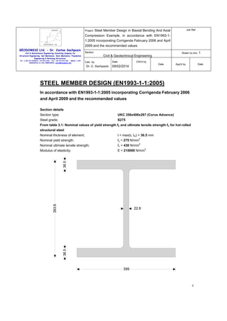
Steel Member Design in Biaxial Bending And Axial
Compression Example, in accordance with EN1993-11:2005 incorporating Corrigenda February 2006 and April
2009 and the recommended values
GEODOMISI Ltd. - Dr. Costas Sachpazis
Civil & Geotechnical Engineering Consulting Company for
Structural Engineering, Soil Mechanics, Rock Mechanics, Foundation
Engineering & Retaining Structures.
Tel.: (+30) 210 5238127, 210 5711263 - Fax.:+30 210 5711461 - Mobile: (+30)
6936425722 & (+44) 7585939944, costas@sachpazis.info
Section
Sheet no./rev. 1
Civil & Geotechnical Engineering
Date
Calc. by
Dr. C. Sachpazis
Chk'd by
Date
09/02/2014
App'd by
Date
Partial factors - Section 6.1
Resistance of cross-sections;
γM0 = 1.00
Resistance of members to instability;
γM1 = 1.00
Resistance of tensile members to fracture;
γM2 = 1.25
Lateral restraint
Distance between major axis restraints;
Ly = 5000 mm
Distance between minor axis restraints;
Lz = 5000 mm
Effective length factors
Effective length factor in major axis;
Ky = 0.700
Effective length factor in minor axis;
Kz = 1.000
Effective length factor for torsion;
KLT = 1.000
Classification of cross sections - Section 5.5
2
ε = √[235 N/mm / fy] = 0.92
Internal compression parts subject to bending and compression - Table 5.2 (sheet 1 of 3)
Width of section;
c = d = 290.2 mm
α = min([h / 2 + NEd / (2 × tw × fy) - (tf+ r)] / c, 1) =
1.000
c / tw = 13.9 × ε <= 396 × ε / (13 × α - 1);
Class 1
Outstand flanges - Table 5.2 (sheet 2 of 3)
Width of section;
c = (b - tw - 2 × r) / 2 = 173 mm
c / tf = 5.1 × ε <= 9 × ε;
Class 1
Section is class 1
Check shear - Section 6.2.6
Height of web;
Shear area factor;
hw = h - 2 × tf = 320.6 mm
η = 1.000
hw / tw < 72 × ε / η
Shear buckling resistance can be ignored
Design shear force parallel to z axis;
Vz,Ed = 200 kN
Shear area - cl 6.2.6(3);
Av = max(A - 2 × b × tf + (tw + 2 × r) × tf, η × hw × tw)
2
= 9378 mm
Design shear resistance - cl 6.2.6(2);
Vc,z,Rd = Vpl,z,Rd = Av × (fy / √[3]) / γM0 = 1489 kN
PASS - Design shear resistance exceeds design shear force
Design shear force parallel to y axis;
Vy,Ed = 30 kN
Shear area - cl 6.2.6(3);
Av = max(2 × b × tf - (tw + 2 × r) × tf, A - (hw × tw)) =
29325 mm
2
Design shear resistance - cl 6.2.6(2);
Vc,y,Rd = Vpl,y,Rd = Av × (fy / √[3]) / γM0 = 4656 kN
PASS - Design shear resistance exceeds design shear force
2](data:image/gif;base64,R0lGODlhAQABAIAAAAAAAP///yH5BAEAAAAALAAAAAABAAEAAAIBRAA7)
Recommended
Recommended
More Related Content
What's hot
What's hot (20)
Viewers also liked
Similar to Sachpazis: Steel member design in biaxial bending and axial compression example EN 1993 1-1-2005_
Similar to Sachpazis: Steel member design in biaxial bending and axial compression example EN 1993 1-1-2005_ (20)
More from Dr.Costas Sachpazis
More from Dr.Costas Sachpazis (20)
Recently uploaded
Recently uploaded (20)
Sachpazis: Steel member design in biaxial bending and axial compression example EN 1993 1-1-2005_
- 1. Project: Job Ref. Steel Member Design in Biaxial Bending And Axial Compression Example, in accordance with EN1993-11:2005 incorporating Corrigenda February 2006 and April 2009 and the recommended values GEODOMISI Ltd. - Dr. Costas Sachpazis Civil & Geotechnical Engineering Consulting Company for Structural Engineering, Soil Mechanics, Rock Mechanics, Foundation Engineering & Retaining Structures. Tel.: (+30) 210 5238127, 210 5711263 - Fax.:+30 210 5711461 - Mobile: (+30) 6936425722 & (+44) 7585939944, costas@sachpazis.info Section Sheet no./rev. 1 Civil & Geotechnical Engineering Calc. by Dr. C. Sachpazis Date Chk'd by Date 09/02/2014 App'd by Date STEEL MEMBER DESIGN (EN1993-1-1:2005) In accordance with EN1993-1-1:2005 incorporating Corrigenda February 2006 and April 2009 and the recommended values Section details Section type; UKC 356x406x287 (Corus Advance) Steel grade; S275 From table 3.1: Nominal values of yield strength fy and ultimate tensile strength fu for hot rolled structural steel Nominal thickness of element; t = max(tf, tw) = 36.5 mm Nominal yield strength; fy = 275 N/mm Nominal ultimate tensile strength; fu = 430 N/mm Modulus of elasticity; E = 210000 N/mm 2 2 2 1
- 2. Project: Job Ref. Steel Member Design in Biaxial Bending And Axial Compression Example, in accordance with EN1993-11:2005 incorporating Corrigenda February 2006 and April 2009 and the recommended values GEODOMISI Ltd. - Dr. Costas Sachpazis Civil & Geotechnical Engineering Consulting Company for Structural Engineering, Soil Mechanics, Rock Mechanics, Foundation Engineering & Retaining Structures. Tel.: (+30) 210 5238127, 210 5711263 - Fax.:+30 210 5711461 - Mobile: (+30) 6936425722 & (+44) 7585939944, costas@sachpazis.info Section Sheet no./rev. 1 Civil & Geotechnical Engineering Date Calc. by Dr. C. Sachpazis Chk'd by Date 09/02/2014 App'd by Date Partial factors - Section 6.1 Resistance of cross-sections; γM0 = 1.00 Resistance of members to instability; γM1 = 1.00 Resistance of tensile members to fracture; γM2 = 1.25 Lateral restraint Distance between major axis restraints; Ly = 5000 mm Distance between minor axis restraints; Lz = 5000 mm Effective length factors Effective length factor in major axis; Ky = 0.700 Effective length factor in minor axis; Kz = 1.000 Effective length factor for torsion; KLT = 1.000 Classification of cross sections - Section 5.5 2 ε = √[235 N/mm / fy] = 0.92 Internal compression parts subject to bending and compression - Table 5.2 (sheet 1 of 3) Width of section; c = d = 290.2 mm α = min([h / 2 + NEd / (2 × tw × fy) - (tf+ r)] / c, 1) = 1.000 c / tw = 13.9 × ε <= 396 × ε / (13 × α - 1); Class 1 Outstand flanges - Table 5.2 (sheet 2 of 3) Width of section; c = (b - tw - 2 × r) / 2 = 173 mm c / tf = 5.1 × ε <= 9 × ε; Class 1 Section is class 1 Check shear - Section 6.2.6 Height of web; Shear area factor; hw = h - 2 × tf = 320.6 mm η = 1.000 hw / tw < 72 × ε / η Shear buckling resistance can be ignored Design shear force parallel to z axis; Vz,Ed = 200 kN Shear area - cl 6.2.6(3); Av = max(A - 2 × b × tf + (tw + 2 × r) × tf, η × hw × tw) 2 = 9378 mm Design shear resistance - cl 6.2.6(2); Vc,z,Rd = Vpl,z,Rd = Av × (fy / √[3]) / γM0 = 1489 kN PASS - Design shear resistance exceeds design shear force Design shear force parallel to y axis; Vy,Ed = 30 kN Shear area - cl 6.2.6(3); Av = max(2 × b × tf - (tw + 2 × r) × tf, A - (hw × tw)) = 29325 mm 2 Design shear resistance - cl 6.2.6(2); Vc,y,Rd = Vpl,y,Rd = Av × (fy / √[3]) / γM0 = 4656 kN PASS - Design shear resistance exceeds design shear force 2
- 3. Project: Job Ref. Steel Member Design in Biaxial Bending And Axial Compression Example, in accordance with EN1993-11:2005 incorporating Corrigenda February 2006 and April 2009 and the recommended values GEODOMISI Ltd. - Dr. Costas Sachpazis Civil & Geotechnical Engineering Consulting Company for Structural Engineering, Soil Mechanics, Rock Mechanics, Foundation Engineering & Retaining Structures. Tel.: (+30) 210 5238127, 210 5711263 - Fax.:+30 210 5711461 - Mobile: (+30) 6936425722 & (+44) 7585939944, costas@sachpazis.info Section Sheet no./rev. 1 Civil & Geotechnical Engineering Date Calc. by Dr. C. Sachpazis Chk'd by Date 09/02/2014 App'd by Date Check bending moment major (y-y) axis - Section 6.2.5 Design bending moment; My,Ed = 450 kNm Design bending resistance moment - eq 6.13; Mc,y,Rd = Mpl,y,Rd = Wpl.y × fy / γM0 = 1598.4 kNm Slenderness ratio for lateral torsional buckling Correction factor - Table 6.6; kc = 0.603 2 C1 = 1 / kc = 2.75 Curvature factor; g = √[1 - (Iz / Iy)] = 0.783 Poissons ratio; ν = 0.3 Shear modulus; G = E / [2 × (1 + ν)] = 80769 N/mm Unrestrained length; L = 1.00 × Lz = 5000 mm 2 Elastic critical buckling moment; 2 2 2 2 Mcr = C1 × π × E × Iz / (L × g) × √[Iw / Iz + L × G × It / (π × E × Iz)] = 29413.9 kNm Slenderness ratio for lateral torsional buckling; λLT = √[Wpl.y × fy / Mcr] = 0.233 Limiting slenderness ratio; λLT,0 = 0.4 λLT < λLT,0 - Lateral torsional buckling can be ignored Design resistance for buckling - Section 6.3.2.1 Buckling curve - Table 6.5; b Imperfection factor - Table 6.3; αLT = 0.34 Correction factor for rolled sections; β = 0.75 LTB reduction determination factor; φLT = 0.5 × [1 + αLT × (λLT -λLT,0) + β ×λLT ] = 2 0.492 LTB reduction factor - eq 6.57; 2 2 2 χLT = min(1 / [φLT + √(φLT - β ×λLT )], 1, 1 /λLT ) = 1.000 2 f = min(1 - 0.5 × (1 - kc)× [1 - 2 × (λLT - 0.8) ], 1) = Modification factor; 0.929 Modified LTB reduction factor - eq 6.58; χLT,mod = min(χLT / f, 1) = 1.000 Design buckling resistance moment - eq 6.55; Mb,Rd = χLT,mod × Wpl.y × fy / γM1 = 1598.4 kNm PASS - Design buckling resistance moment exceeds design bending moment Check bending moment minor (z-z) axis - Section 6.2.5 Design bending moment; Mz,Ed = 125 kNm Design bending resistance moment - eq 6.13; Mc,z,Rd = Mpl,z,Rd = Wpl.z × fy / γM0 = 811 kNm PASS - Design bending resistance moment exceeds design bending moment Check compression - Section 6.2.4 Design compression force; NEd = 4500 kN Design resistance of section - eq 6.10; Nc,Rd = Npl,Rd = A × fy / γM0 = 10057 kN Slenderness ratio for major (y-y) axis buckling Critical buckling length; Lcr,y = Ly × Ky = 3500 mm Critical buckling force; Ncr,y = π2 × ESEC3 × Iy / Lcr,y2 = 168981.8 kN 3
- 4. Project: Job Ref. Steel Member Design in Biaxial Bending And Axial Compression Example, in accordance with EN1993-11:2005 incorporating Corrigenda February 2006 and April 2009 and the recommended values GEODOMISI Ltd. - Dr. Costas Sachpazis Section Civil & Geotechnical Engineering Consulting Company for Structural Engineering, Soil Mechanics, Rock Mechanics, Foundation Engineering & Retaining Structures. Sheet no./rev. 1 Civil & Geotechnical Engineering Tel.: (+30) 210 5238127, 210 5711263 - Fax.:+30 210 5711461 - Mobile: (+30) 6936425722 & (+44) 7585939944, costas@sachpazis.info Calc. by Dr. C. Sachpazis Date Chk'd by Date 09/02/2014 Slenderness ratio for buckling - eq 6.50; App'd by Date λy = √[A × fy / Ncr,y] = 0.244 Design resistance for buckling - Section 6.3.1.1 Buckling curve - Table 6.2; b Imperfection factor - Table 6.1; αy = 0.34 Buckling reduction determination factor; φy = 0.5 × [1 + αy × (λy - 0.2) + λy ] = 0.537 Buckling reduction factor - eq 6.49; χy = min(1 / [φy + √(φy - λy )], 1) = 0.984 Design buckling resistance - eq 6.47; Nb,y,Rd = χy × A × fy / γM1 = 9899.8 kN 2 2 2 PASS - Design buckling resistance exceeds design compression force Slenderness ratio for minor (z-z) axis buckling Critical buckling length; Lcr,z = Lz × Kz = 5000 mm Critical buckling force; Ncr,z = π × ESEC3 × Iz / Lcr,z = 32065.3 kN Slenderness ratio for buckling - eq 6.50; λz = √[A × fy / Ncr,z] = 0.560 2 2 Design resistance for buckling - Section 6.3.1.1 Buckling curve - Table 6.2; c Imperfection factor - Table 6.1; αz = 0.49 Buckling reduction determination factor; φz = 0.5 × [1 + αz × (λz - 0.2) + λz ] = 0.745 2 2 √(φz 2 - λz )], 1) = 0.809 Buckling reduction factor - eq 6.49; χz = min(1 / [φz + Design buckling resistance - eq 6.47; Nb,z,Rd = χz × A × fy / γM1 = 8134.2 kN PASS - Design buckling resistance exceeds design compression force Check torsional and torsional-flexural buckling - Section 6.3.1.4 Torsional buckling length factor; KT = 1.00 Torsional buckling length; Lcr,T = max(Ly, Lz) × KT = 5000 mm Distance from shear centre to centroid in y axis; y0 = 0.0 mm Distance from shear centre to centroid in z axis; z0 = 0.0 mm Radius of gyration; i0 = √[iy + iz ] = 194.6 mm Elastic critical torsional buckling force; 2 2 2 2 2 Ncr,T = 1 / i0 × [G × It + π × ESEC3 × Iw / Lcr,T ] = 57695.2 kN Torsion factor; 2 βT = 1 - (y0 / i0) = 1.000 Elastic critical torsional-flexural buckling force 2 2 Ncr,TF = Ncr,y / (2 × βT) × [1 + Ncr,T / Ncr,y - √[(1 - Ncr,T / Ncr,y) + 4 × (y0 / i0) × Ncr,T / Ncr,y]] = 57695.2 kN Elastic critical buckling force; Ncr = min(Ncr,T, Ncr,TF) = 57695.2 kN Slenderness ratio for torsional buckling - eq 6.52; λT = √[A × fy / Ncr] = 0.418 Design resistance for buckling - Section 6.3.1.1 Buckling curve - Table 6.2; c Imperfection factor - Table 6.1; αT = 0.49 Buckling reduction determination factor; φT = 0.5 × [1 + αT × (λT - 0.2) + λT ] = 0.640 2 2 2 Buckling reduction factor - eq 6.49; χT = min(1 / [φT + √(φT - λT )], 1) = 0.888 Design buckling resistance - eq 6.47; Nb,T,Rd = χT × A × fy / γM1 = 8930.8 kN 4
- 5. Project: Job Ref. Steel Member Design in Biaxial Bending And Axial Compression Example, in accordance with EN1993-11:2005 incorporating Corrigenda February 2006 and April 2009 and the recommended values GEODOMISI Ltd. - Dr. Costas Sachpazis Section Civil & Geotechnical Engineering Consulting Company for Structural Engineering, Soil Mechanics, Rock Mechanics, Foundation Engineering & Retaining Structures. Sheet no./rev. 1 Civil & Geotechnical Engineering Tel.: (+30) 210 5238127, 210 5711263 - Fax.:+30 210 5711461 - Mobile: (+30) 6936425722 & (+44) 7585939944, costas@sachpazis.info Calc. by Dr. C. Sachpazis Date Chk'd by Date 09/02/2014 App'd by Date PASS - Design buckling resistance exceeds design compression force Combined bending and axial force - Section 6.2.9 Normal force to plastic resistance force ratio; n = NEd / Npl,Rd = 0.45 Web area to gross area ratio; aw = min((A - 2 × b × tf) / A, 0.5) = 0.20 Design plastic moment resistance (y-y) - eq 6.13; Mpl,y,Rd = Wpl.y × fy / γM0 = 1598.4 kNm Reduced plastic mnt resistance (y-y)- eq 6.36; MN,y,Rd = Mpl,y,Rd × min((1 - n) / (1 - 0.5 × aw), 1) = 983.3 kNm Design plastic moment resistance (z-z) - eq 6.13; Mpl,z,Rd = Wpl.z × fy / γM0 = 811.0 kNm Reduced plastic mnt resistance (z-z) - eq 6.38; MN,z,Rd = Mpl,z,Rd × (1 - ((n-aw) / (1- aw)) ) = 735.0 2 kNm Parameter introducing effect of biaxial bending; α_bi = 2.00 Parameter introducing effect of biaxial bending; β_bi = max(5 × n, 1) = 2.24 Interaction formula – eq (6.41); (My,Ed / MN,y,Rd)α _bi + (Mz,Ed / MN,z,Rd)β _bi = 0.228 PASS - Reduced bending resistance moment exceeds design bending moment Check combined bending and compression - Section 6.3.3 Equivalent uniform moment factors - Table B.3; Cmy = 0.400 Cmz = 0.600 CmLT = 0.400 Interaction factors kij for members susceptible to torsional deformations - Table B.2 Characteristic moment resistance; My,Rk = Wpl.y × fy = 1598.4 kNm Characteristic moment resistance; Mz,Rk = Wpl.z × fy = 811 kNm Characteristic resistance to normal force; NRk = A × fy = 10057 kN Interaction factors; kyy = Cmy × [1 + min(λy - 0.2, 0.8) × NEd / (χy × NRk / γM1)] = 0.408 kzy = 1 - 0.1 × max(1,λz) × NEd / ((CmLT - 0.25) × χz × NRk / γM1) = 0.631 kzz = Cmz × [1 + min(2 ×λz - 0.6, 1.4) × NEd / (χz × NRk / γM1)] = 0.773 kyz = 0.6 × kzz = 0.464 Interaction formulae - eq 6.61 & eq 6.62; NEd / (χy × NRk / γM1) + kyy × My,Ed / (χLT × My,Rk / γM1) + kyz × Mz,Ed / (Mz,Rk / γM1) = 0.641 NEd / (χz × NRk / γM1) + kzy × My,Ed / (χLT × My,Rk / γM1) + kzz × Mz,Ed / (Mz,Rk / γM1) = 0.850 PASS - Combined bending and compression checks are satisfied 5