Sachpazis: Raft Foundation Analysis and Design for a two Storey House Project project
•
3 likes•763 views

This document provides an analysis and design of a raft foundation for a two-story house project. It includes definitions of the soil properties, raft slab geometry, reinforcement, and other structural elements. Calculations are shown for checks of internal slab bearing pressure, bending moments, shear forces, and reinforcement requirements in accordance with relevant code standards. The analysis confirms that the applied bearing pressure is less than the allowable soil pressure and that the provided reinforcement is adequate.

Recommended
Recommended
More Related Content
What's hot
What's hot (20)
Similar to Sachpazis: Raft Foundation Analysis and Design for a two Storey House Project project
Similar to Sachpazis: Raft Foundation Analysis and Design for a two Storey House Project project (20)
More from Dr.Costas Sachpazis
More from Dr.Costas Sachpazis (20)
Recently uploaded
Recently uploaded (20)
Sachpazis: Raft Foundation Analysis and Design for a two Storey House Project project
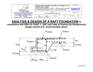
- 1. - Dr. Costas Sachpazis Civil & Geotechnical Engineering Consulting Company for Structural Engineering, Soil Mechanics, Rock Mechanics, Foundation Engineering & Retaining Structures. Tel.: (+30) 210 5238127, 210 5711263-Fax:+30 210 440171 Mobile: (+30) 6936425722 www.geodomisi.com - costas@sachpazis.info Project: Raft Foundation Analysis and Design for a 2 Storey House Project. In accordance with BS8110: PART 1: 1997 and Code of Practice for Geotechnical design and the U.K. recommended values. Job Ref. 0519025 www.geodomisi.com info@geodomisi.com Section Civil & Geotechnical Engineering Sheet no./rev. 1 Calc. Dr. C. Sachpazis Date 20/05/2021 Chk'd by Date App'd by Date Page 1 of 25 ANALYSIS & DESIGN OF A RAFT FOUNDATION In accordance with BS8110: PART 1: 1997 and Code of Practice for Geotechnical design and the U.K. recommended values. hedge hboot bedge bboot aedge hslab hhcoreslab hhcorethick Asslabtop Asedgetop Asslabbtm Asedgebtm Asedgelink
- 2. - Dr. Costas Sachpazis Civil & Geotechnical Engineering Consulting Company for Structural Engineering, Soil Mechanics, Rock Mechanics, Foundation Engineering & Retaining Structures. Tel.: (+30) 210 5238127, 210 5711263-Fax:+30 210 440171 Mobile: (+30) 6936425722 www.geodomisi.com - costas@sachpazis.info Project: Raft Foundation Analysis and Design for a 2 Storey House Project. In accordance with BS8110: PART 1: 1997 and Code of Practice for Geotechnical design and the U.K. recommended values. Job Ref. 0519025 www.geodomisi.com info@geodomisi.com Section Civil & Geotechnical Engineering Sheet no./rev. 1 Calc. Dr. C. Sachpazis Date 20/05/2021 Chk'd by Date App'd by Date Page 2 of 25 Soil and raft definition Soil definition Allowable bearing pressure; qallow = 50.0 kN/m2 Number of types of soil forming sub-soil; Two or more types Soil density; Firm to loose Depth of hardcore beneath slab; hhcoreslab = 150 mm; (Dispersal allowed for bearing pressure check) Depth of hardcore beneath thickenings; hhcorethick = 0 mm; (Dispersal allowed for bearing pressure check) Density of hardcore; hcore = 20.0 kN/m3 Basic assumed diameter of local depression; depbasic = 3500mm Diameter under slab modified for hardcore; depslab = depbasic - hhcoreslab = 3350 mm Diameter under thickenings modified for hardcore; depthick = depbasic - hhcorethick = 3500 mm Raft slab definition Max dimension/max dimension between joints; lmax = 13.100 m Slab thickness; hslab = 200 mm Concrete strength; fcu = 35 N/mm2 Poissons ratio of concrete; = 0.2 Slab mesh reinforcement strength; fyslab = 500 N/mm2 Partial safety factor for steel reinforcement; s = 1.15 From C&CA document ‘Concrete ground floors’ Table 5
- 3. - Dr. Costas Sachpazis Civil & Geotechnical Engineering Consulting Company for Structural Engineering, Soil Mechanics, Rock Mechanics, Foundation Engineering & Retaining Structures. Tel.: (+30) 210 5238127, 210 5711263-Fax:+30 210 440171 Mobile: (+30) 6936425722 www.geodomisi.com - costas@sachpazis.info Project: Raft Foundation Analysis and Design for a 2 Storey House Project. In accordance with BS8110: PART 1: 1997 and Code of Practice for Geotechnical design and the U.K. recommended values. Job Ref. 0519025 www.geodomisi.com info@geodomisi.com Section Civil & Geotechnical Engineering Sheet no./rev. 1 Calc. Dr. C. Sachpazis Date 20/05/2021 Chk'd by Date App'd by Date Page 3 of 25 Minimum mesh required in top for shrinkage; A142; Actual mesh provided in top; 2 x A393 (Asslabtop = 786 mm2 /m) Mesh provided in bottom; A393 (Asslabbtm = 393 mm2 /m) Top mesh bar diameter; slabtop = 10 mm Bottom mesh bar diameter; slabbtm = 10 mm Cover to top reinforcement; ctop = 20 mm Cover to bottom reinforcement; cbtm = 35 mm Average effective depth of top reinforcement; dtslabav = hslab - ctop - slabtop = 170 mm Average effective depth of bottom reinforcement; dbslabav = hslab - cbtm - slabbtm = 155 mm Overall average effective depth; dslabav = (dtslabav + dbslabav)/2 = 163 mm Minimum effective depth of top reinforcement; dtslabmin = dtslabav - slabtop/2 = 165 mm Minimum effective depth of bottom reinforcement; dbslabmin = dbslabav - slabbtm/2 = 150 mm Edge beam definition Overall depth; hedge = 450 mm Width; bedge = 450 mm Depth of boot; hboot = 225 mm Width of boot; bboot = 180 mm Angle of chamfer to horizontal; edge = 60 deg Strength of main bar reinforcement; fy = 500 N/mm2
- 4. - Dr. Costas Sachpazis Civil & Geotechnical Engineering Consulting Company for Structural Engineering, Soil Mechanics, Rock Mechanics, Foundation Engineering & Retaining Structures. Tel.: (+30) 210 5238127, 210 5711263-Fax:+30 210 440171 Mobile: (+30) 6936425722 www.geodomisi.com - costas@sachpazis.info Project: Raft Foundation Analysis and Design for a 2 Storey House Project. In accordance with BS8110: PART 1: 1997 and Code of Practice for Geotechnical design and the U.K. recommended values. Job Ref. 0519025 www.geodomisi.com info@geodomisi.com Section Civil & Geotechnical Engineering Sheet no./rev. 1 Calc. Dr. C. Sachpazis Date 20/05/2021 Chk'd by Date App'd by Date Page 4 of 25 Strength of link reinforcement; fys = 500 N/mm2 Reinforcement provided in top; 3 H25 bars (Asedgetop = 1473 mm2 ) Reinforcement provided in bottom; 3 H25 bars (Asedgebtm = 1473 mm2 ) Link reinforcement provided; 2 H12 legs at 275 ctrs (Asv/sv = 0.823 mm) Bottom cover to links; cbeam = 35 mm Effective depth of top reinforcement; dedgetop = hedge - ctop - slabtop - edgelink - edgetop/2 = 395 mm Effective depth of bottom reinforcement; dedgebtm = hedge - cbeam - edgelink - edgebtm/2 = 391 mm Boot main reinforcement; H8 bars at 350 ctrs (Asboot = 144 mm2 /m) Effective depth of boot reinforcement; dboot = hboot - cbeam - boot/2 = 186 mm Internal beam definition
- 5. - Dr. Costas Sachpazis Civil & Geotechnical Engineering Consulting Company for Structural Engineering, Soil Mechanics, Rock Mechanics, Foundation Engineering & Retaining Structures. Tel.: (+30) 210 5238127, 210 5711263-Fax:+30 210 440171 Mobile: (+30) 6936425722 www.geodomisi.com - costas@sachpazis.info Project: Raft Foundation Analysis and Design for a 2 Storey House Project. In accordance with BS8110: PART 1: 1997 and Code of Practice for Geotechnical design and the U.K. recommended values. Job Ref. 0519025 www.geodomisi.com info@geodomisi.com Section Civil & Geotechnical Engineering Sheet no./rev. 1 Calc. Dr. C. Sachpazis Date 20/05/2021 Chk'd by Date App'd by Date Page 5 of 25 Overall depth; hint = 450 mm Width; bint = 450 mm Angle of chamfer to horizontal; int = 60 deg hint bint aint hslab hhcoreslab hhcorethick Asslabtop Asinttop Asslabbtm Asintbtm Asintlink
- 6. - Dr. Costas Sachpazis Civil & Geotechnical Engineering Consulting Company for Structural Engineering, Soil Mechanics, Rock Mechanics, Foundation Engineering & Retaining Structures. Tel.: (+30) 210 5238127, 210 5711263-Fax:+30 210 440171 Mobile: (+30) 6936425722 www.geodomisi.com - costas@sachpazis.info Project: Raft Foundation Analysis and Design for a 2 Storey House Project. In accordance with BS8110: PART 1: 1997 and Code of Practice for Geotechnical design and the U.K. recommended values. Job Ref. 0519025 www.geodomisi.com info@geodomisi.com Section Civil & Geotechnical Engineering Sheet no./rev. 1 Calc. Dr. C. Sachpazis Date 20/05/2021 Chk'd by Date App'd by Date Page 6 of 25 Strength of main bar reinforcement; fy = 500 N/mm2 Strength of link reinforcement; fys = 500 N/mm2 Reinforcement provided in top; 3 H20 bars (Asinttop = 942 mm2 ) Reinforcement provided in bottom; 3 H20 bars (Asintbtm = 942 mm2 ) Link reinforcement provided; 2 H10 legs at 225 ctrs (Asv/sv = 0.698 mm) Effective depth of top reinforcement; dinttop = hint - ctop - 2 slabtop - inttop/2 = 400 mm Effective depth of bottom reinforcement; dintbtm = hint - cbeam - intlink - intbtm/2 = 395 mm Internal slab design checks Basic loading Slab self weight; wslab = 24 kN/m3 hslab = 4.8 kN/m2 Hardcore; whcoreslab = hcore hhcoreslab = 3.0 kN/m2 Applied loading Uniformly distributed dead load; wDudl = 0.1 kN/m2 Uniformly distributed live load; wLudl = 1.5 kN/m2 Internal slab bearing pressure check Total uniform load at formation level; wudl = wslab + whcoreslab + wDudl + wLudl = 9.4 kN/m2 PASS - wudl <= qallow - Applied bearing pressure is less than allowable
- 7. - Dr. Costas Sachpazis Civil & Geotechnical Engineering Consulting Company for Structural Engineering, Soil Mechanics, Rock Mechanics, Foundation Engineering & Retaining Structures. Tel.: (+30) 210 5238127, 210 5711263-Fax:+30 210 440171 Mobile: (+30) 6936425722 www.geodomisi.com - costas@sachpazis.info Project: Raft Foundation Analysis and Design for a 2 Storey House Project. In accordance with BS8110: PART 1: 1997 and Code of Practice for Geotechnical design and the U.K. recommended values. Job Ref. 0519025 www.geodomisi.com info@geodomisi.com Section Civil & Geotechnical Engineering Sheet no./rev. 1 Calc. Dr. C. Sachpazis Date 20/05/2021 Chk'd by Date App'd by Date Page 7 of 25 Internal slab bending and shear check Applied bending moments Span of slab; lslab = depslab + dtslabav = 3520 mm Ultimate self weight udl; wswult = 1.4 wslab = 6.7 kN/m2 Self weight moment at centre; Mcsw = wswult lslab 2 (1 + ) / 64 = 1.6 kNm/m Self weight moment at edge; Mesw = wswult lslab 2 / 32 = 2.6 kNm/m Self weight shear force at edge; Vsw = wswult lslab / 4 = 5.9 kN/m Moments due to applied uniformly distributed loads Ultimate applied udl; wudlult = 1.4 wDudl + 1.6 wLudl = 2.5 kN/m2 Moment at centre; Mcudl = wudlult lslab 2 (1 + ) / 64 = 0.6 kNm/m Moment at edge; Meudl = wudlult lslab 2 / 32 = 1.0 kNm/m Shear force at edge; Vudl = wudlult lslab / 4 = 2.2 kN/m Resultant moments and shears Total moment at edge; Me = 3.6 kNm/m Total moment at centre; Mc = 2.2 kNm/m Total shear force; V = 8.1 kN/m Reinforcement required in top K factor; Kslabtop = Me/(fcu dtslabav 2 ) = 0.004
- 8. - Dr. Costas Sachpazis Civil & Geotechnical Engineering Consulting Company for Structural Engineering, Soil Mechanics, Rock Mechanics, Foundation Engineering & Retaining Structures. Tel.: (+30) 210 5238127, 210 5711263-Fax:+30 210 440171 Mobile: (+30) 6936425722 www.geodomisi.com - costas@sachpazis.info Project: Raft Foundation Analysis and Design for a 2 Storey House Project. In accordance with BS8110: PART 1: 1997 and Code of Practice for Geotechnical design and the U.K. recommended values. Job Ref. 0519025 www.geodomisi.com info@geodomisi.com Section Civil & Geotechnical Engineering Sheet no./rev. 1 Calc. Dr. C. Sachpazis Date 20/05/2021 Chk'd by Date App'd by Date Page 8 of 25 Lever arm; zslabtop = dtslabav min(0.95, 0.5 + (0.25 - Kslabtop/0.9)) = 161.5 mm Area of steel required for bending; Asslabtopbend = Me/((1.0/s) fyslab zslabtop) = 51 mm2 /m Minimum area of steel required; Asslabmin = 0.0013 hslab = 260 mm2 /m Area of steel required; Asslabtopreq = max(Asslabtopbend, Asslabmin) = 260 mm2 /m PASS - Asslabtopreq <= Asslabtop - Area of reinforcement provided in top to span local depressions is adequate Reinforcement required in bottom K factor; Kslabbtm = Mc/(fcu dbslabav 2 ) = 0.003 Lever arm; zslabbtm = dbslabav min(0.95, 0.5 + (0.25 - Kslabbtm/0.9)) = 147.3 mm Area of steel required for bending; Asslabbtmbend = Mc/((1.0/s) fyslab zslabbtm) = 34 mm2 /m Area of steel required; Asslabbtmreq = max(Asslabbtmbend, Asslabmin) = 260 mm2 /m PASS - Asslabbtmreq <= Asslabbtm - Area of reinforcement provided in bottom to span local depressions is adequate Shear check Applied shear stress; v = V/dtslabmin = 0.049 N/mm2 Tension steel ratio; = 100 Asslabtop/dtslabmin = 0.476 From BS8110-1:1997 - Table 3.8; Design concrete shear strength; vc = 0.689 N/mm2 PASS - v <= vc - Shear capacity of the slab is adequate
- 9. - Dr. Costas Sachpazis Civil & Geotechnical Engineering Consulting Company for Structural Engineering, Soil Mechanics, Rock Mechanics, Foundation Engineering & Retaining Structures. Tel.: (+30) 210 5238127, 210 5711263-Fax:+30 210 440171 Mobile: (+30) 6936425722 www.geodomisi.com - costas@sachpazis.info Project: Raft Foundation Analysis and Design for a 2 Storey House Project. In accordance with BS8110: PART 1: 1997 and Code of Practice for Geotechnical design and the U.K. recommended values. Job Ref. 0519025 www.geodomisi.com info@geodomisi.com Section Civil & Geotechnical Engineering Sheet no./rev. 1 Calc. Dr. C. Sachpazis Date 20/05/2021 Chk'd by Date App'd by Date Page 9 of 25 Internal slab deflection check Basic allowable span to depth ratio; Ratiobasic = 26.0 Moment factor; Mfactor = Mc/dbslabav 2 = 0.090 N/mm2 Steel service stress; fs = 2/3 fyslab Asslabbtmbend/Asslabbtm = 28.501 N/mm2 Modification factor; MFslab = min(2.0, 0.55 + [(477N/mm2 - fs)/(120 (0.9N/mm2 + Mfactor))]) MFslab = 2.000 Modified allowable span to depth ratio; Ratioallow = Ratiobasic MFslab = 52.000 Actual span to depth ratio; Ratioactual = lslab/ dbslabav = 22.710 PASS - Ratioactual <= Ratioallow - Slab span to depth ratio is adequate Edge beam design checks Basic loading Hardcore; whcorethick = hcore hhcorethick = 0.0 kN/m2 Edge beam Rectangular beam element; wbeam = 24 kN/m3 hedge bedge = 4.9 kN/m Boot element; wboot = 24 kN/m3 hboot bboot = 1.0 kN/m Chamfer element; wchamfer = 24 kN/m3 (hedge - hslab)2 /(2 tan(edge)) = 0.4 kN/m Slab element; wslabelmt = 24 kN/m3 hslab (hedge - hslab)/tan(edge) = 0.7 kN/m Edge beam self weight; wedge = wbeam + wboot + wchamfer + wslabelmt = 7.0 kN/m
- 10. - Dr. Costas Sachpazis Civil & Geotechnical Engineering Consulting Company for Structural Engineering, Soil Mechanics, Rock Mechanics, Foundation Engineering & Retaining Structures. Tel.: (+30) 210 5238127, 210 5711263-Fax:+30 210 440171 Mobile: (+30) 6936425722 www.geodomisi.com - costas@sachpazis.info Project: Raft Foundation Analysis and Design for a 2 Storey House Project. In accordance with BS8110: PART 1: 1997 and Code of Practice for Geotechnical design and the U.K. recommended values. Job Ref. 0519025 www.geodomisi.com info@geodomisi.com Section Civil & Geotechnical Engineering Sheet no./rev. 1 Calc. Dr. C. Sachpazis Date 20/05/2021 Chk'd by Date App'd by Date Page 10 of 25 Edge load number 1 Load type; Longitudinal line load Dead load; wDedge1 = 45.8 kN/m Live load; wLedge1 = 5.6 kN/m Ultimate load; wultedge1 = 1.4 wDedge1 + 1.6 wLedge1 = 73.1 kN/m Longitudinal line load width; bedge1 = 100 mm Centroid of load from outside face of raft; xedge1 = 230 mm Edge load number 2 Load type; Transverse line load Dead load; wDedge2 = 42.7 kN/m Live load; wLedge2 = 5.6 kN/m Ultimate load; wultedge2 = 1.4 wDedge2 + 1.6 wLedge2 = 68.7 kN/m Transverse line load width; bedge2 = 100 mm Edge beam bearing pressure check Effective bearing width of edge beam; bbearing = bedge + bboot + (hedge - hslab)/tan(edge) = 774 mm Total uniform load at formation level; wudledge = wDudl+wLudl+wedge/bbearing+whcorethick = 10.6 kN/m2 Bearing pressure due to transverse line loads Total dead transverse line load; wDtrans = 42.7 kN/m Total live transverse line load; wLtrans = 5.6 kN/m
- 11. - Dr. Costas Sachpazis Civil & Geotechnical Engineering Consulting Company for Structural Engineering, Soil Mechanics, Rock Mechanics, Foundation Engineering & Retaining Structures. Tel.: (+30) 210 5238127, 210 5711263-Fax:+30 210 440171 Mobile: (+30) 6936425722 www.geodomisi.com - costas@sachpazis.info Project: Raft Foundation Analysis and Design for a 2 Storey House Project. In accordance with BS8110: PART 1: 1997 and Code of Practice for Geotechnical design and the U.K. recommended values. Job Ref. 0519025 www.geodomisi.com info@geodomisi.com Section Civil & Geotechnical Engineering Sheet no./rev. 1 Calc. Dr. C. Sachpazis Date 20/05/2021 Chk'd by Date App'd by Date Page 11 of 25 Total ultimate transverse line load; wulttrans = 68.7 kN/m Minimum width of transverse line loads; btrans = 100 mm Length of trans line load applied to edge beam; ltransapp = bedge + (hedge - hslab)/tan(edge) = 594 mm Total ult trans line load applied to edge beam; Wulttrans = wulttrans ltransapp = 40.9 kN Approx moment capacity of bottom steel; Medgebtm = (1.0/s) fy 0.9 dedgebtm Asedgebtm = 225.0 kNm Max allow dispersal based on moment capacity; pedgemom=[2Medgebtm+(4Medgebtm 2 +2WulttransMedgebtmbtrans)]/Wulttrans pedgemom = 22081 mm Limiting max dispersal to say 5 x beam depth; pedge = min(pedgemom, 5 hedge) = 2250 mm Total dispersal width of transverse line loads; ltrans = 2 pedge + btrans = 4600 mm Bearing pressure due to trans line loads; qtrans = (wDtrans + wLtrans) ltransapp/(ltrans bbearing) = 8.1 kN/m2 Centroid of longitudinal and equivalent line loads from outside face of raft Load x distance for edge load 1; Moment1 = wultedge1 xedge1 = 16.8 kN Sum of ultimate longitud’l and equivalent line loads; UDL = 73.1 kN/m Sum of load x distances; Moment = 16.8 kN Centroid of loads; xbar = Moment/UDL = 230 mm Initially assume no moment transferred into slab due to load/reaction eccentricity Sum of unfactored longitud’l and eff’tive line loads; UDLsls = 51.4 kN/m Allowable bearing width; ballow = 2 xbar + 2 hhcoreslab tan(30) = 633 mm
- 12. - Dr. Costas Sachpazis Civil & Geotechnical Engineering Consulting Company for Structural Engineering, Soil Mechanics, Rock Mechanics, Foundation Engineering & Retaining Structures. Tel.: (+30) 210 5238127, 210 5711263-Fax:+30 210 440171 Mobile: (+30) 6936425722 www.geodomisi.com - costas@sachpazis.info Project: Raft Foundation Analysis and Design for a 2 Storey House Project. In accordance with BS8110: PART 1: 1997 and Code of Practice for Geotechnical design and the U.K. recommended values. Job Ref. 0519025 www.geodomisi.com info@geodomisi.com Section Civil & Geotechnical Engineering Sheet no./rev. 1 Calc. Dr. C. Sachpazis Date 20/05/2021 Chk'd by Date App'd by Date Page 12 of 25 Bearing pressure due to line/point loads; qlinepoint = UDLsls/ ballow = 81.2 kN/m2 Total applied bearing pressure; qedge = qlinepoint + qtrans + wudledge = 99.8 kN/m2 qedge > qallow - The slab is required to resist a moment due to eccentricity Now assume moment due to load/reaction eccentricity is resisted by slab Bearing width required; breq = UDLsls/(qallow - qtrans - wudledge) = 1639 mm Effective bearing width at u/s of slab; breqeff = breq - 2 hhcoreslab tan(30) = 1466 mm Load/reaction eccentricity; e = breqeff/2 - xbar = 503 mm Ultimate moment to be resisted by slab; Mecc = UDL e = 36.8 kNm/m From slab bending check Moment due to depression under slab (hogging); Me = 3.6 kNm/m Total moment to be resisted by slab top steel; Mslabtop = Mecc + Me = 40.3 kNm/m K factor; Kslab = Mslabtop/(fcu dtslabmin 2 ) = 0.042 Lever arm; zslab = dtslabmin min(0.95, 0.5 + (0.25 - Kslab/0.9)) = 157 mm Area of steel required; Asslabreq = Mslabtop/((1.0/s) fy zslab) = 592 mm2 /m PASS - Asslabreq <= Asslabtop - Area of reinforcement provided to transfer moment into slab is adequate The allowable bearing pressure under the edge beam will not be exceeded Library item - B pressure with moment transfer Edge beam bending check Divider for moments due to udl’s; udl = 10.0
- 13. - Dr. Costas Sachpazis Civil & Geotechnical Engineering Consulting Company for Structural Engineering, Soil Mechanics, Rock Mechanics, Foundation Engineering & Retaining Structures. Tel.: (+30) 210 5238127, 210 5711263-Fax:+30 210 440171 Mobile: (+30) 6936425722 www.geodomisi.com - costas@sachpazis.info Project: Raft Foundation Analysis and Design for a 2 Storey House Project. In accordance with BS8110: PART 1: 1997 and Code of Practice for Geotechnical design and the U.K. recommended values. Job Ref. 0519025 www.geodomisi.com info@geodomisi.com Section Civil & Geotechnical Engineering Sheet no./rev. 1 Calc. Dr. C. Sachpazis Date 20/05/2021 Chk'd by Date App'd by Date Page 13 of 25 Divider for moments due to point loads; point = 6.0 Applied bending moments Span of edge beam; ledge = depthick + dedgetop = 3896 mm Ultimate self weight udl; wedgeult = 1.4 wedge = 9.7 kN/m Ultimate slab udl (approx); wedgeslab = max(0 kN/m,1.4wslab((depthick/23/4)-(bedge+(hedge- hslab)/tan(edge)))) wedgeslab = 4.8 kN/m Self weight and slab bending moment; Medgesw = (wedgeult + wedgeslab) ledge 2 /udl = 22.1 kNm Self weight shear force; Vedgesw = (wedgeult + wedgeslab) ledge/2 = 28.4 kN Moments due to applied uniformly distributed loads Ultimate udl (approx); wedgeudl = wudlult depthick/2 3/4 = 3.3 kN/m Bending moment; Medgeudl = wedgeudl ledge 2 /udl = 5.1 kNm Shear force; Vedgeudl = wedgeudl ledge/2 = 6.5 kN Moment and shear due to load number 1 Bending moment; Medge1 = wultedge1 ledge 2 /udl = 110.9 kNm Shear force; Vedge1 = wultedge1 ledge/2 = 142.3 kN Moment and shear due to load number 2 Ultimate point load; Wedge2 = wultedge2 depthick/2 3/4 = 90.2 kN Bending moment; Medge2 = Wedge2 ledge/point = 58.6 kNm
- 14. - Dr. Costas Sachpazis Civil & Geotechnical Engineering Consulting Company for Structural Engineering, Soil Mechanics, Rock Mechanics, Foundation Engineering & Retaining Structures. Tel.: (+30) 210 5238127, 210 5711263-Fax:+30 210 440171 Mobile: (+30) 6936425722 www.geodomisi.com - costas@sachpazis.info Project: Raft Foundation Analysis and Design for a 2 Storey House Project. In accordance with BS8110: PART 1: 1997 and Code of Practice for Geotechnical design and the U.K. recommended values. Job Ref. 0519025 www.geodomisi.com info@geodomisi.com Section Civil & Geotechnical Engineering Sheet no./rev. 1 Calc. Dr. C. Sachpazis Date 20/05/2021 Chk'd by Date App'd by Date Page 14 of 25 Shear force; Vedge2 = Wedge2 = 90.2 kN Resultant moments and shears Total moment (hogging and sagging); Medge = 196.6 kNm Maximum shear force; Vedge = 267.4 kN Reinforcement required in top Width of section in compression zone; bedgetop = bedge + bboot = 630 mm Average web width; bw = bedge + (hedge/tan(edge))/2 = 580 mm K factor; Kedgetop = Medge/(fcu bedgetop dedgetop 2 ) = 0.057 Lever arm; zedgetop = dedgetop min(0.95, 0.5 + (0.25 - Kedgetop/0.9)) = 369 mm Area of steel required for bending; Asedgetopbend = Medge/((1.0/s) fy zedgetop) = 1227 mm2 Minimum area of steel required; Asedgetopmin = 0.0013 1.0 bw hedge = 339 mm2 Area of steel required; Asedgetopreq = max(Asedgetopbend, Asedgetopmin) = 1227 mm2 PASS - Asedgetopreq <= Asedgetop - Area of reinforcement provided in top of edge beams is adequate Reinforcement required in bottom Width of section in compression zone; bedgebtm = bedge + (hedge - hslab)/tan(edge) + 0.1 ledge = 984 mm K factor; Kedgebtm = Medge/(fcu bedgebtm dedgebtm 2 ) = 0.037 Lever arm; zedgebtm = dedgebtm min(0.95, 0.5 + (0.25 - Kedgebtm/0.9)) = 371 mm Area of steel required for bending; Asedgebtmbend = Medge/((1.0/s) fy zedgebtm) = 1219 mm2
- 15. - Dr. Costas Sachpazis Civil & Geotechnical Engineering Consulting Company for Structural Engineering, Soil Mechanics, Rock Mechanics, Foundation Engineering & Retaining Structures. Tel.: (+30) 210 5238127, 210 5711263-Fax:+30 210 440171 Mobile: (+30) 6936425722 www.geodomisi.com - costas@sachpazis.info Project: Raft Foundation Analysis and Design for a 2 Storey House Project. In accordance with BS8110: PART 1: 1997 and Code of Practice for Geotechnical design and the U.K. recommended values. Job Ref. 0519025 www.geodomisi.com info@geodomisi.com Section Civil & Geotechnical Engineering Sheet no./rev. 1 Calc. Dr. C. Sachpazis Date 20/05/2021 Chk'd by Date App'd by Date Page 15 of 25 Minimum area of steel required; Asedgebtmmin = 0.0013 1.0 bw hedge = 339 mm2 Area of steel required; Asedgebtmreq = max(Asedgebtmbend, Asedgebtmmin) = 1219 mm2 PASS - Asedgebtmreq <= Asedgebtm - Area of reinforcement provided in bottom of edge beams is adequate Edge beam shear check Applied shear stress; vedge = Vedge/(bw dedgetop) = 1.166 N/mm2 Tension steel ratio; edge = 100 Asedgetop/(bw dedgetop) = 0.642 From BS8110-1:1997 - Table 3.8 Design concrete shear strength; vcedge = 0.612 N/mm2 vedge > vcedge + 0.4N/mm2 - Therefore designed links required Link area to spacing ratio required; Asv_upon_svreqedge = (vedge - vcedge) bw/((1.0/s) fys) = 0.739 mm Link area to spacing ratio provided; Asv_upon_svprovedge = Nedgelinkedgelink 2 /(4svedge) = 0.823 mm PASS - Asv_upon_svreqedge <= Asv_upon_svprovedge - Shear reinforcement provided in edge beams is adequate Boot design check Effective cantilever span; lboot = bboot + dboot/2 = 273 mm Approximate ultimate bearing pressure; qult = 1.55 qallow = 77.5 kN/m2 Cantilever moment; Mboot = qult lboot 2 /2 = 2.9 kNm/m Shear force; Vboot = qult lboot = 21.2 kN/m K factor; Kboot = Mboot/(fcu dboot 2 ) = 0.002 Lever arm; zboot = dboot min(0.95, 0.5 + (0.25 - Kboot/0.9)) = 177 mm
- 16. - Dr. Costas Sachpazis Civil & Geotechnical Engineering Consulting Company for Structural Engineering, Soil Mechanics, Rock Mechanics, Foundation Engineering & Retaining Structures. Tel.: (+30) 210 5238127, 210 5711263-Fax:+30 210 440171 Mobile: (+30) 6936425722 www.geodomisi.com - costas@sachpazis.info Project: Raft Foundation Analysis and Design for a 2 Storey House Project. In accordance with BS8110: PART 1: 1997 and Code of Practice for Geotechnical design and the U.K. recommended values. Job Ref. 0519025 www.geodomisi.com info@geodomisi.com Section Civil & Geotechnical Engineering Sheet no./rev. 1 Calc. Dr. C. Sachpazis Date 20/05/2021 Chk'd by Date App'd by Date Page 16 of 25 Area of reinforcement required; Asbootreq = Mboot/((1.0/s) fyboot zboot) = 38 mm2 /m PASS - Asbootreq <= Asboot - Area of reinforcement provided in boot is adequate for bending Applied shear stress; vboot = Vboot/dboot = 0.114 N/mm2 Tension steel ratio; boot = 100 Asboot/dboot = 0.077 From BS8110-1:1997 - Table 3.8 Design concrete shear strength;vcboot = 0.365 N/mm2 PASS - vboot <= vcboot - Shear capacity of the boot is adequate Corner design checks Basic loading Corner bearing pressure check Total uniform load at formation level; wudlcorner = wDudl+wLudl+wedge/bbearing+whcorethick = 10.6 kN/m2 PASS - wudlcorner <= qallow - Applied bearing pressure is less than allowable Corner beam bending check Cantilever span of edge beam; lcorner = depthick/(2) + dedgetop/2 = 2673 mm Moment and shear due to self weight Ultimate self weight udl; wedgeult = 1.4 wedge = 9.7 kN/m Average ultimate slab udl (approx); wcornerslab = max(0 kN/m,1.4wslab(depthick/((2)2)-(bedge+(hedge- hslab)/tan(edge))))
- 17. - Dr. Costas Sachpazis Civil & Geotechnical Engineering Consulting Company for Structural Engineering, Soil Mechanics, Rock Mechanics, Foundation Engineering & Retaining Structures. Tel.: (+30) 210 5238127, 210 5711263-Fax:+30 210 440171 Mobile: (+30) 6936425722 www.geodomisi.com - costas@sachpazis.info Project: Raft Foundation Analysis and Design for a 2 Storey House Project. In accordance with BS8110: PART 1: 1997 and Code of Practice for Geotechnical design and the U.K. recommended values. Job Ref. 0519025 www.geodomisi.com info@geodomisi.com Section Civil & Geotechnical Engineering Sheet no./rev. 1 Calc. Dr. C. Sachpazis Date 20/05/2021 Chk'd by Date App'd by Date Page 17 of 25 wcornerslab = 4.3 kN/m Self weight and slab bending moment; Mcornersw = (wedgeult + wcornerslab) lcorner 2 /2 = 50.2 kNm Self weight and slab shear force; Vcornersw = (wedgeult + wcornerslab) lcorner = 37.6 kN Moment and shear due to udls Maximum ultimate udl; wcornerudl = ((1.4wDudl)+(1.6wLudl)) depthick/(2) = 6.3 kN/m Bending moment; Mcornerudl = wcornerudl lcorner 2 /6 = 7.5 kNm Shear force; Vcornerudl = wcornerudl lcorner/2 = 8.4 kN Resultant moments and shears Total design moment; Mcorner = Mcornersw+ Mcornerudl = 57.7 kNm Total design shear force; Vcorner = Vcornersw+ Vcornerudl = 46.0 kN Reinforcement required in top of edge beam K factor; Kcorner = Mcorner/(fcu bedgetop dedgetop 2 ) = 0.017 Lever arm; zcorner = dedgetop min(0.95, 0.5 + (0.25 - Kcorner/0.9)) = 376 mm Area of steel required for bending; Ascornerbend = Mcorner/((1.0/s) fy zcorner) = 353 mm2 Minimum area of steel required; Ascornermin = Asedgetopmin = 339 mm2 Area of steel required; Ascorner = max(Ascornerbend, Ascornermin) = 353 mm2 PASS - Ascorner <= Asedgetop - Area of reinforcement provided in top of edge beams at corners is adequate Corner beam shear check
- 18. - Dr. Costas Sachpazis Civil & Geotechnical Engineering Consulting Company for Structural Engineering, Soil Mechanics, Rock Mechanics, Foundation Engineering & Retaining Structures. Tel.: (+30) 210 5238127, 210 5711263-Fax:+30 210 440171 Mobile: (+30) 6936425722 www.geodomisi.com - costas@sachpazis.info Project: Raft Foundation Analysis and Design for a 2 Storey House Project. In accordance with BS8110: PART 1: 1997 and Code of Practice for Geotechnical design and the U.K. recommended values. Job Ref. 0519025 www.geodomisi.com info@geodomisi.com Section Civil & Geotechnical Engineering Sheet no./rev. 1 Calc. Dr. C. Sachpazis Date 20/05/2021 Chk'd by Date App'd by Date Page 18 of 25 Average web width; bw = bedge + (hedge/tan(edge))/2 = 580 mm Applied shear stress; vcorner = Vcorner/(bw dedgetop) = 0.200 N/mm2 Tension steel ratio; corner = 100 Asedgetop/(bw dedgetop) = 0.642 From BS8110-1:1997 - Table 3.8 Design concrete shear strength; vccorner = 0.610 N/mm2 vcorner <= vccorner + 0.4N/mm2 - Therefore minimum links required Link area to spacing ratio required; Asv_upon_svreqcorner = 0.4N/mm2 bw/((1.0/s) fys) = 0.534 mm Link area to spacing ratio provided; Asv_upon_svprovedge = Nedgelinkedgelink 2 /(4svedge) = 0.823 mm PASS - Asv_upon_svreqcorner <= Asv_upon_svprovedge - Shear reinforcement provided in edge beams at corners is adequate Corner beam deflection check Basic allowable span to depth ratio; Ratiobasiccorner = 7.0 Moment factor; Mfactorcorner = Mcorner/(bedgetop dedgetop 2 ) = 0.586 N/mm2 Steel service stress; fscorner = 2/3 fy Ascornerbend/Asedgetop = 79.961 N/mm2 Modification factor; MFcorner=min(2.0,0.55+[(477N/mm2 - fscorner)/(120(0.9N/mm2 +Mfactorcorner))]) MFcorner = 2.000 Modified allowable span to depth ratio; Ratioallowcorner = Ratiobasiccorner MFcorner = 14.000 Actual span to depth ratio; Ratioactualcorner = lcorner/ dedgetop = 6.758
- 19. - Dr. Costas Sachpazis Civil & Geotechnical Engineering Consulting Company for Structural Engineering, Soil Mechanics, Rock Mechanics, Foundation Engineering & Retaining Structures. Tel.: (+30) 210 5238127, 210 5711263-Fax:+30 210 440171 Mobile: (+30) 6936425722 www.geodomisi.com - costas@sachpazis.info Project: Raft Foundation Analysis and Design for a 2 Storey House Project. In accordance with BS8110: PART 1: 1997 and Code of Practice for Geotechnical design and the U.K. recommended values. Job Ref. 0519025 www.geodomisi.com info@geodomisi.com Section Civil & Geotechnical Engineering Sheet no./rev. 1 Calc. Dr. C. Sachpazis Date 20/05/2021 Chk'd by Date App'd by Date Page 19 of 25 PASS - Ratioactualcorner <= Ratioallowcorner - Edge beam span to depth ratio is adequate Internal beam design checks Basic loading Hardcore; whcorethick = hcore hhcorethick = 0.0 kN/m2 Internal beam self weight; wint=24 kN/m3 [(hintbint)+(hint-hslab)2 /tan(int)+2hslab(hint-hslab)/tan(int)] wint = 7.1 kN/m Internal beam load number 1 Load type; Longitudinal line load Dead load; wDint1 = 17.0 kN/m Live load; wLint1 = 4.0 kN/m Ultimate load; wultint1 = 1.4 wDint1 + 1.6 wLint1 = 30.2 kN/m Longitudinal line load width; bint1 = 140 mm Centroid of load from centreline of beam; xint1 = 0 mm Internal beam load number 2 Load type; Half transverse line load; Dead load; wDint2 = 21.6 kN/m Live load; wLint2 = 4.0 kN/m Ultimate load; wultint2 = 1.4 wDint2 + 1.6 wLint2 = 36.6 kN/m Transverse line load width; bint2 = 140 mm
- 20. - Dr. Costas Sachpazis Civil & Geotechnical Engineering Consulting Company for Structural Engineering, Soil Mechanics, Rock Mechanics, Foundation Engineering & Retaining Structures. Tel.: (+30) 210 5238127, 210 5711263-Fax:+30 210 440171 Mobile: (+30) 6936425722 www.geodomisi.com - costas@sachpazis.info Project: Raft Foundation Analysis and Design for a 2 Storey House Project. In accordance with BS8110: PART 1: 1997 and Code of Practice for Geotechnical design and the U.K. recommended values. Job Ref. 0519025 www.geodomisi.com info@geodomisi.com Section Civil & Geotechnical Engineering Sheet no./rev. 1 Calc. Dr. C. Sachpazis Date 20/05/2021 Chk'd by Date App'd by Date Page 20 of 25 Location of load; +ve side of centreline Internal beam bearing pressure check Total uniform load at formation level; wudlint = wDudl+wLudl+whcorethick+24kN/m3 hint = 12.4 kN/m2 Effective point load due to transverse line/point loads Effective point load due to load 2 (Line load); Wint2 = wultint2 [bint/2 + (hint - hslab)/tan(int)] = 13.5 kN Total effective point load; Wint = 13.5 kN Minimum width of effective point load; bintmin = 140 mm Approximate longitudinal dispersal of effective point load Approx moment capacity of bottom steel; Mintbtm = (1.0/s) fy 0.9 dintbtm Asintbtm = 145.7 kNm Max allow dispersal based on moment capacity; pintmom = [2Mintbtm + (4Mintbtm 2 +2WintMintbtmbintmin)]/Wint pintmom = 43129 mm Limiting max dispersal to say 5 x beam depth; pint = min(pintmom, 5 hint) = 2250 mm Total dispersal length of effective point load; linteff = 2 pint + bintmin = 4640 mm Equivalent and total beam line loads Equivalent ultimate udl of internal load 2; wintudl2 = Wint2/linteff = 2.9 kN/m Equivalent unfactored udl of internal load 2; wintudl2sls = wintudl2 (wDint2 + wLint2)/wultint2 = 2.0 kN/m Sum of factored longitud’l and eff’tive line loads; UDLint = 33.1 kN/m
- 21. - Dr. Costas Sachpazis Civil & Geotechnical Engineering Consulting Company for Structural Engineering, Soil Mechanics, Rock Mechanics, Foundation Engineering & Retaining Structures. Tel.: (+30) 210 5238127, 210 5711263-Fax:+30 210 440171 Mobile: (+30) 6936425722 www.geodomisi.com - costas@sachpazis.info Project: Raft Foundation Analysis and Design for a 2 Storey House Project. In accordance with BS8110: PART 1: 1997 and Code of Practice for Geotechnical design and the U.K. recommended values. Job Ref. 0519025 www.geodomisi.com info@geodomisi.com Section Civil & Geotechnical Engineering Sheet no./rev. 1 Calc. Dr. C. Sachpazis Date 20/05/2021 Chk'd by Date App'd by Date Page 21 of 25 Sum of unfactored longitud’l and eff’tive line loads; UDLslsint = 23.0 kN/m Centroid of loads from centreline of internal beam Load x distance for internal load 1; Momentint1 = wultint1 xint1 = 0.0 kN Load x distance for internal load 2; Momentint2 = wintudl2 (bint/2+(hint-hslab)/tan(int))/2 = 0.5 kN Sum of load x distances; Momentint = 0.5 kN Centroid of loads; xbarint = Momentint/UDLint = 16.3 mm Moment due to eccentricity to be resisted by slab; Meccint = UDLint abs(xbarint) = 0.5 kNm/m Assume moment due to eccentricity is resisted equally by top steel of slab on one side and bottom steel of slab on other From slab bending check Moment due to depression under slab (hogging); Me = 3.6 kNm/m Total moment to be resisted by slab top steel; Mslabtopint = Meccint/2 + Me = 3.9 kNm/m K factor; Kslabtopint = Mslabtopint/(fcu dtslabmin 2 ) = 0.004 Lever arm; zslabtopint = dtslabmin min(0.95, 0.5 + (0.25 - Kslabtopint/0.9)) = 157 mm Area of steel required; Asslabtopintreq = Mslabtopint/((1.0/s) fyslab zslabtopint) = 57 mm2 /m PASS - Asslabtopintreq <= Asslabtop - Area of reinforcement in top of slab is adequate to transfer moment into slab Mt to be resisted by slab btm stl due to load ecc’ty; Mslabbtmint = Meccint/2 = 0.3 kNm/m K factor; Kslabbtmint = Mslabbtmint/(fcu dbslabmin 2 ) = 0.000 Lever arm; zslabbtmint = dbslabmin min(0.95, 0.5 + (0.25-Kslabbtmint/0.9)) = 143 mm Area of steel required in bottom; Asslabbtmintreq = Mslabbtmint/((1.0/s) fyslab zslabbtmint) = 4 mm2 /m
- 22. - Dr. Costas Sachpazis Civil & Geotechnical Engineering Consulting Company for Structural Engineering, Soil Mechanics, Rock Mechanics, Foundation Engineering & Retaining Structures. Tel.: (+30) 210 5238127, 210 5711263-Fax:+30 210 440171 Mobile: (+30) 6936425722 www.geodomisi.com - costas@sachpazis.info Project: Raft Foundation Analysis and Design for a 2 Storey House Project. In accordance with BS8110: PART 1: 1997 and Code of Practice for Geotechnical design and the U.K. recommended values. Job Ref. 0519025 www.geodomisi.com info@geodomisi.com Section Civil & Geotechnical Engineering Sheet no./rev. 1 Calc. Dr. C. Sachpazis Date 20/05/2021 Chk'd by Date App'd by Date Page 22 of 25 PASS - Asslabbtmintreq <= Asslabbtm - Area of reinforcement in bottom of slab is adequate to transfer moment into slab Bearing pressure Initially check bearing pressure based on beam soffit/chamfer width only Allowable bearing width; bbearint=min(2(bint/2tan(int)+hint)/(1+tan(int)),bint+2(hint- hslab)/tan(int)) bbearint = 615 mm Bearing pressure due to line/point loads; qlinepointint = UDLslsint/bbearint = 37.5 kN/m2 Total applied bearing pressure; qint = qlinepointint + wudlint = 49.9 kN/m2 PASS - qint <= qallow - Allowable bearing pressure is not exceeded Internal beam bending check Divider for moments due to udl’s; udl = 10.0 Divider for moments due to point loads; point = 6.0 Applied bending moments Span of internal beam; lint = depthick + dinttop = 3900 mm Ultimate self weight udl; wintult = 1.4 wint = 10.0 kN/m Ultimate slab udl (approx); wintslab = max(0 kN/m,1.4wslab((depthick3/4)-(bint+2(hint- hslab)/tan(int)))) wintslab = 12.7 kN/m
- 23. - Dr. Costas Sachpazis Civil & Geotechnical Engineering Consulting Company for Structural Engineering, Soil Mechanics, Rock Mechanics, Foundation Engineering & Retaining Structures. Tel.: (+30) 210 5238127, 210 5711263-Fax:+30 210 440171 Mobile: (+30) 6936425722 www.geodomisi.com - costas@sachpazis.info Project: Raft Foundation Analysis and Design for a 2 Storey House Project. In accordance with BS8110: PART 1: 1997 and Code of Practice for Geotechnical design and the U.K. recommended values. Job Ref. 0519025 www.geodomisi.com info@geodomisi.com Section Civil & Geotechnical Engineering Sheet no./rev. 1 Calc. Dr. C. Sachpazis Date 20/05/2021 Chk'd by Date App'd by Date Page 23 of 25 Self weight and slab bending moment; Mintsw = (wintult + wintslab) lint 2 /udl = 34.4 kNm Self weight shear force; Vintsw = (wintult + wintslab) lint/2 = 44.1 kN Moments due to applied uniformly distributed loads Ultimate udl (approx); wintudl = wudlult depthick 3/4 = 6.7 kN/m Bending moment; Mintudl = wintudl lint 2 /udl = 10.1 kNm Shear force; Vintudl = wintudl lint/2 = 13.0 kN Moment and shear due to load number 1 Bending moment; Mint1 = wultint1 lint 2 /udl = 45.9 kNm Shear force; Vint1 = wultint1 lint/2 = 58.9 kN Moment and shear due to load number 2 Ultimate point load; Wint2 = wultint2 depthick/2 3/4 = 48.1 kN Bending moment; Mint2 = Wint2 lint/point = 31.3 kNm Shear force; Vint2 = Wint2 = 48.1 kN Resultant moments and shears Total moment (hogging and sagging); Mint = 121.8 kNm Maximum shear force; Vint = 164.1 kN Reinforcement required in top Width of section in compression zone; binttop = bint = 450 mm
- 24. - Dr. Costas Sachpazis Civil & Geotechnical Engineering Consulting Company for Structural Engineering, Soil Mechanics, Rock Mechanics, Foundation Engineering & Retaining Structures. Tel.: (+30) 210 5238127, 210 5711263-Fax:+30 210 440171 Mobile: (+30) 6936425722 www.geodomisi.com - costas@sachpazis.info Project: Raft Foundation Analysis and Design for a 2 Storey House Project. In accordance with BS8110: PART 1: 1997 and Code of Practice for Geotechnical design and the U.K. recommended values. Job Ref. 0519025 www.geodomisi.com info@geodomisi.com Section Civil & Geotechnical Engineering Sheet no./rev. 1 Calc. Dr. C. Sachpazis Date 20/05/2021 Chk'd by Date App'd by Date Page 24 of 25 Average web width; bwint = bint + hint/tan(int) = 710 mm K factor; Kinttop = Mint/(fcu binttop dinttop 2 ) = 0.048 Lever arm; zinttop = dinttop min(0.95, 0.5 + (0.25 - Kinttop/0.9)) = 377 mm Area of steel required for bending; Asinttopbend = Mint/((1.0/s) fy zinttop) = 742 mm2 Minimum area of steel; Asinttopmin = 0.0013 bwint hint = 415 mm2 Area of steel required; Asinttopreq = max(Asinttopbend, Asinttopmin) = 742 mm2 PASS - Asinttopreq <= Asinttop - Area of reinforcement provided in top of internal beams is adequate Reinforcement required in bottom Width of section in compression zone; bintbtm = bint + 2 (hint - hslab)/tan(int) + 0.2 lint = 1519 mm K factor; Kintbtm = Mint/(fcu bintbtm dintbtm 2 ) = 0.015 Lever arm; zintbtm = dintbtm min(0.95, 0.5 + (0.25 - Kintbtm/0.9)) = 375 mm Area of steel required for bending; Asintbtmbend = Mint/((1.0/s) fy zintbtm) = 746 mm2 Minimum area of steel required; Asintbtmmin = 0.0013 1.0 bwint hint = 415 mm2 Area of steel required; Asintbtmreq = max(Asintbtmbend, Asintbtmmin) = 746 mm2 PASS - Asintbtmreq <= Asintbtm - Area of reinforcement provided in bottom of internal beams is adequate Internal beam shear check Applied shear stress; vint = Vint/(bwint dinttop) = 0.578 N/mm2 Tension steel ratio; int = 100 Asinttop/(bwint dinttop) = 0.332 From BS8110-1:1997 - Table 3.8
- 25. - Dr. Costas Sachpazis Civil & Geotechnical Engineering Consulting Company for Structural Engineering, Soil Mechanics, Rock Mechanics, Foundation Engineering & Retaining Structures. Tel.: (+30) 210 5238127, 210 5711263-Fax:+30 210 440171 Mobile: (+30) 6936425722 www.geodomisi.com - costas@sachpazis.info Project: Raft Foundation Analysis and Design for a 2 Storey House Project. In accordance with BS8110: PART 1: 1997 and Code of Practice for Geotechnical design and the U.K. recommended values. Job Ref. 0519025 www.geodomisi.com info@geodomisi.com Section Civil & Geotechnical Engineering Sheet no./rev. 1 Calc. Dr. C. Sachpazis Date 20/05/2021 Chk'd by Date App'd by Date Page 25 of 25 Design concrete shear strength; vcint = 0.490 N/mm2 vint <= vcint + 0.4N/mm2 - Therefore minimum links required Link area to spacing ratio required; Asv_upon_svreqint = 0.4N/mm2 bwint/((1.0/s) fys) = 0.653 mm Link area to spacing ratio provided; Asv_upon_svprovint = Nintlinkintlink 2 /(4svint) = 0.698 mm PASS - Asv_upon_svreqint <= Asv_upon_svprovint - Shear reinforcement provided in internal beams is adequate GEODOMISI Ltd. - Dr. Costas Sachpazis Civil & Geotechnical Engineering Consulting Company for Structural Engineering, Soil Mechanics, Rock Mechanics, Foundation Engineering & Retaining Structures. Tel.: (+30) 210 5238127, 210 5711263 - Fax.:+30 210 5711461 - Mobile: (+30) 6936425722 & (+44) 7585939944, www.geodomisi.com - costas@sachpazis.info