SlideShare a Scribd company logo
1 of 200
Download to read offline
15 Select the grip on the right side of the extrusion, and drag it toward the Center (Left/Right)
reference plane.
16 Repeat for the left grip until the solid form displays as shown.
17 Align and lock both ends of the extrusion to the inside of the side panels:
■ On the Tools toolbar, click .
■ Select the inside face of the left panel.
■ Select the left side of the extrusion, and lock the alignment.
Adding a Top Shelf | 401
■ Select the inside face of the right panel.
■ Select the right side of the extrusion, and lock the alignment.
18 On the View toolbar, click (Default 3D View).
19 On the View Control Bar, click Model Graphics Style ➤ Shading with Edges.
Flex the family
20 On the Design Bar, click Family Types.
21 In the Family Types dialog, for Name, select 60x18x60.
22 Click Apply.
23 Repeat for 36x12x36 and 72x18x48.
402 | Chapter 15 Creating a Bookcase (Furniture) Family
24 Click OK.
25 Proceed to the next exercise, Changing the Shape of the Side Panels on page 403.
Changing the Shape of the Side Panels
In this exercise, you change the shape of the bookcase side panels from rectangular to rounded. To accomplish
this, you edit the panel sketches. In anticipation of future changes, you created the sketches in the Ref. Level
view so that the side panels could be given a rounded face.
Training File
■ Continue to use the family that you used in the previous exercise, Bookcase.rfa, or open training file
ImperialFamiliesFurnitureBookcase_05.rfa.
■ If you are using the supplied training file, click File menu ➤ Save As.
■ In the left pane of the Save As dialog, click Training Files, and save the file as
ImperialFamiliesFurnitureBookcase.rfa.
Modify the left panel
1 In the Project Browser, under Floor Plans, double-click Ref. Level.
2 Select the left panel, and on the Options Bar, click Edit.
3 On the Design Bar, click Modify.
Changing the Shape of the Side Panels | 403
4 Select the left vertical line of the panel sketch, and press DELETE.
5 Replace the deleted line with a rounded panel:
■ On the Design Bar, click Lines.
■ On the Options Bar, click (Arc passing through three points).
■ In the location where you deleted the panel line, select the top endpoint.
■ Select the bottom endpoint.
■ Click to place the arc.
■ Modify the arc dimension to 2'.
6 On the Design Bar, click Modify.
7 Select the arc, and on the Options Bar, click (Element Properties).
8 In the Element Properties dialog, under Graphics, select Center Mark Visible, and click OK.
Displaying the center mark allows you to dimension to the center of the circle.
9 On the Design Bar, click Dimension.
10 Dimension the Left reference plane and the center of the circle.
This ensures that the arc center will stay at a fixed distance from the Left reference plane.
404 | Chapter 15 Creating a Bookcase (Furniture) Family
Modify the right panel
11 Using the same method, create a rounded panel on the right side of the bookcase.
12 On the Design Bar, click Finish Sketch.
13 On the View toolbar, click (Default 3D View).
14 Proceed to the next exercise, Creating and Assigning Subcategories on page 406.
Changing the Shape of the Side Panels | 405
Creating and Assigning Subcategories
In this exercise, you add a number of subcategories to the bookcase family so you can assign materials to its
individual components, such as the shelves, door, base plate, panels, and top. After you create the
subcategories, you assign each piece of the bookcase geometry to one of the subcategories.
Later in this tutorial, you apply different materials to each subcategory, allowing you to vary the materials
that you apply to each component of the bookcase.
Training File
■ Continue to use the family that you used in the previous exercise, Bookcase.rfa, or open training file
ImperialFamiliesFurnitureBookcase_06.rfa.
■ If you are using the supplied training file, click File menu ➤ Save As.
■ In the left pane of the Save As dialog, click Training Files, and save the file as
ImperialFamiliesFurnitureBookcase.rfa.
Create subcategories in the Furniture category
1 Click Settings menu ➤ Object Styles.
The Object Styles dialog displays. In the next steps, you add subcategories under the main
Furniture category. Later in this tutorial, you will use this dialog to specify default materials for
each subcategory that you create.
2 In the Object Styles dialog, on the Model Object tab, under Category, select Furniture.
3 Under Modify Subcategories, click New.
4 In the New Subcategory dialog, for Name, enter Base, and click OK.
5 Using the same method, create additional subcategories:
■ Top
■ Panels
■ Shelves
■ Door
6 When you finish creating subcategories, click OK.
Assign solid forms to the corresponding subcategories
7 While pressing CTRL, select the side and back panels of the bookcase.
406 | Chapter 15 Creating a Bookcase (Furniture) Family
On the Options Bar, click (Element Properties).
8 In the Element Properties dialog, under Identity Data, for Subcategory, select Panels, and click
OK.
9 On the Design Bar, click Modify.
10 Using the same method, assign the corresponding subcategory to the top and the base of the
bookcase.
Although you created Door and Shelves categories, you have not created the door and shelf
geometry. You will create and assign them in subsequent exercises.
11 Proceed to the next exercise, Adding Shelves on page 407.
Adding Shelves
In this exercise, you add 3 shelves to the bookcase family. You create the shelves by sketching multiple
closed loops. You then apply parameters to control the shelf spacing.
Adding Shelves | 407
Training File
■ Continue to use the family that you used in the previous exercise, Bookcase.rfa, or open training file
ImperialFamiliesFurnitureBookcase_07.rfa.
■ If you are using the supplied training file, click File menu ➤ Save As.
■ In the left pane of the Save As dialog, click Training Files, and save the file as
ImperialFamiliesFurnitureBookcase.rfa.
Sketch the shelves
1 In the Project Browser, under Elevations, double-click Front.
2 On the Design Bar, click Solid Form ➤ Solid Extrusion.
3 On the Options Bar, click (Rectangle).
4 Draw 3 stepped rectangles as shown.
5 Align and lock the left edges:
■ On the Tools toolbar, click (Align).
■ Select the left edge of the bottom rectangle, and then the left edge of the rectangle above.
■ Lock the alignment.
■ Select the left edge of the bottom rectangle, and then the left edge of the top rectangle.
408 | Chapter 15 Creating a Bookcase (Furniture) Family
■ Lock the alignment.
6 Repeat the process for the right edges of the rectangles.
7 Align and lock the bottom shelf edges with the inside face of the side panels:
■ On the Tools toolbar, click .
■ Select the reference plane at the top of the base, select the bottom edge of the lowest rectangle,
and lock the alignment.
Apply the panel_thickness parameter to the shelves
8 On the Design Bar, click Dimension.
9 Place individual dimensions (not a string) as shown to control shelf thickness and spacing.
Adding Shelves | 409
10 Select the dimensions controlling the thickness of the shelf sketches, and apply the
panel_thickness parameter.
Create and apply maximum and minimum shelf spacing parameters
11 Select the dimension between the bottom and middle shelves.
12 On the Options Bar, for Label, click <Add parameter>.
13 In the Parameter Properties dialog, under Parameter Name, enter shelf_maximum_spacing, and
click OK.
14 On the Design Bar, click Modify.
15 Select the dimension between the middle and top shelves, and create a shelf_minimum_spacing
parameter.
410 | Chapter 15 Creating a Bookcase (Furniture) Family
16 On the Design Bar, click Extrusion Properties.
17 In the Element Properties dialog:
■ Under Constraints, for Extrusion End, enter 1'.
This is a temporary value as you will later constrain the shelves to the back panel.
■ Click OK.
Finish the shelves
18 On the Design Bar, click Finish Sketch.
19 In the Project Browser, under Floor Plans, double-click Ref. Level.
20 Select the shelf.
21 Drag and lock the sides of the shelf to the inside faces of the side panels.
22 Drag the top grip up and lock the edge of the shelf to the inside of the back panel.
23 On the View toolbar, click (Default 3D View).
Adding Shelves | 411
Flex the family
24 On the Design Bar, click Family Types.
25 In the Family Types dialog, for Name, verify 72x18x48 is selected.
26 Under Other, for shelf_minimum_spacing, enter 6''.
27 For shelf_maximum_spacing, enter 1'.
28 Click Apply.
29 For Name, select 60x18x60.
30 Under Other, for shelf_minimum_spacing, enter 6''.
Shelf spacing can be specified with default values for each family type.
31 For shelf_maximum_spacing, enter 1'.
32 Click Apply.
412 | Chapter 15 Creating a Bookcase (Furniture) Family
33 For Name, select 36x12x36.
34 Under Other, for shelf_minimum_spacing, enter 4''.
35 For shelf_maximum_spacing, enter 4''.
36 Click Apply.
37 For Name, select 72x18x48, and click OK.
Assign the Shelves subcategory
38 On the Design Bar, click Modify.
39 Select the shelves, and click (Element Properties).
40 In the Element Properties dialog, under Identity Data, for Subcategory, select Shelves.
41 Click OK.
42 Proceed to the next exercise, Adding an Enclosure Panel on page 413.
Adding an Enclosure Panel
In this exercise, you add a vertical enclosure panel to the top shelf of the bookcase.
Adding an Enclosure Panel | 413
In the next exercise, you create a door to complete the enclosure.
Training File
■ Continue to use the family that you used in the previous exercise, Bookcase.rfa, or open training file
ImperialFamiliesFurnitureBookcase_08.rfa.
■ If you are using the supplied training file, click File menu ➤ Save As.
■ In the left pane of the Save As dialog, click Training Files, and save the file as
ImperialFamiliesFurnitureBookcase.rfa.
Create a reference plane for the vertical enclosure panel
1 In the Project Browser, under Elevations, double-click Front.
414 | Chapter 15 Creating a Bookcase (Furniture) Family
2 On the Design Bar, click Ref Plane.
3 Sketch a vertical reference plane between the left and center planes.
4 On the Design Bar, click Modify.
5 Select the reference plane, and on the Options Bar, click (Element Properties).
6 In the Element Properties dialog, under Identity Data, for Name, enter Enclosure.
7 Click OK.
Create a parameter to control the enclosure length
8 On the Design Bar, click Dimension.
9 Select the Left reference plane.
10 Select the Enclosure reference plane.
11 Click to place the dimension.
12 On the Design Bar, click Modify.
Adding an Enclosure Panel | 415
13 Select the dimension you just placed, and on the Options Bar, for Label, select <Add parameter>.
14 In the Parameter Properties dialog, under Parameter Data, for Name, enter enclosure_length,
and click OK.
15 On the Design Bar, click Family Types.
16 In the Family Types dialog, under Other, for enclosure_length, enter 2', and click Apply.
17 Apply the same value for enclosure_length to all the family types.
18 For Name, select 72x18x48, and click OK.
Sketch the enclosure panel
19 On the Design Bar, click Solid Form ➤ Solid Extrusion.
20 On the Options Bar, click (Rectangle).
21 Draw the sketch clear of reference planes.
416 | Chapter 15 Creating a Bookcase (Furniture) Family
22 On the Tools toolbar, click (Align).
23 Select the Enclosure reference plane.
24 Select the left edge of the rectangle, and lock the alignment.
25 Select the underside of the bookcase top.
26 Select the top of the rectangle, and lock the alignment.
Adding an Enclosure Panel | 417
27 Select the top face of the top shelf.
28 Select the bottom line of the rectangle, and lock the alignment.
29 Dimension between the Enclosure reference plane and the right edge of the rectangle:
■ On the Design Bar, click Dimension.
■ Select the Enclosure reference plane.
■ Select the right edge of the sketch.
418 | Chapter 15 Creating a Bookcase (Furniture) Family
■ Click to place the dimension.
Add the panel_thickness parameter
30 On the Design Bar, click Modify.
31 Select the dimension that you just placed.
32 On the Options Bar, for Label, select panel_thickness.
33 On the Design Bar, click Finish Sketch.
Adding an Enclosure Panel | 419
Align the panel
34 In the Project Browser, under Floor Plans, double-click Ref. Level.
35 Select the panel.
36 Drag the top grip to align with the inside face of the back panel and lock the alignment.
37 Drag the bottom grip to align with the inside face of the top shelf.
420 | Chapter 15 Creating a Bookcase (Furniture) Family
38 On the View toolbar, click (Default 3D View).
39 Assign a subcategory to the panel:
■ Select the panel, and on the Options Bar, click (Element Properties).
■ In the Element Properties dialog, under Identity Data, for Subcategory, select Panels, and
click OK.
■ Press ESC.
40 Proceed to the next exercise, Adding a Door on page 421.
Adding a Door
In this exercise, you add a door with a circular opening and a glass panel that adjusts to fit the enclosure.
The same parameter that positions the vertical panel controls the door width.
Adding a Door | 421
Training File
■ Continue to use the family that you used in the previous exercise, Bookcase.rfa, or open training file
ImperialFamiliesFurnitureBookcase_09.rfa.
■ If you are using the supplied training file, click File menu ➤ Save As.
■ In the left pane of the Save As dialog, click Training Files, and save the file as
ImperialFamiliesFurnitureBookcase.rfa.
Use concentric rectangles to create the door
1 In the Project Browser, under Elevations, double-click Front.
2 On the Design Bar, click Solid Form ➤ Solid Extrusion.
3 Click Set Work Plane.
4 In the Work Plane dialog, under Specify a new Work Plane, verify that Name and Reference
Plane: Front are selected.
5 Click OK.
6 On the Options Bar, click (Rectangle).
7 Sketch 2 concentric rectangles as shown.
The inner sketch will be interpreted as a void by the software.
422 | Chapter 15 Creating a Bookcase (Furniture) Family
8 On the Design Bar, click Modify.
9 On the Tools toolbar, click (Align).
10 Align and lock the 4 edges of the outer sketch:
■ Align and lock the left edge to the inside of the side panel.
■ Align the top edge to the bottom of the downturn (top shelf).
■ Align the right edge to the outside face of the vertical panel.
■ Align the bottom edge to the top face of the shelf.
11 On the View Control Bar, click the current scale, and select 3''=1'-0''.
12 Dimension the door sketch to locate the opening:
■ On the Design Bar, click Dimension.
■ Move the cursor over one of the lines of the outer sketch, press TAB until it highlights, and
select it.
Adding a Door | 423
■ Move the cursor to the parallel line of the inner sketch, select the line, and click to place the
dimension.
■ Using the same method, dimension the remaining sketch lines.
13 On the Design Bar, click Modify.
14 Select the inner sketch lines individually and adjust each offset distance to 3''.
15 On the Design Bar, click Extrusion Properties.
16 In the Element Properties dialog, under Constraints, for Extrusion End, click .
424 | Chapter 15 Creating a Bookcase (Furniture) Family
17 In the Associate Family Parameter dialog, under Existing family parameters of compatible type,
select panel_thickness.
18 Click OK twice.
19 On the Design Bar, click Finish Sketch.
Draw a solid form for the door glass
20 On the Design Bar, click Solid Form ➤ Solid Extrusion.
21 Click Set Work Plane.
22 In the Work Plane dialog, under Specify a new Work Plane, verify that Name and Reference
Plane: Front are selected.
23 Click OK.
24 On the Options Bar, click .
25 Sketch a rectangle directly on top of the rectangle that represents the void (the inner rectangle
sketch).
26 Lock each line.
Because you sketched the rectangle on top of the other, alignment between the rectangles is
assumed. This is a fast way to align elements. It is only applicable where there are not multiple
superimposed faces or reference planes.
27 With the glass sketch still selected, on the Design Bar, click Extrusion Properties.
28 In the Element Properties dialog:
■ Under Constraints, for Extrusion End, enter 1/2''.
■ For Extrusion Start, enter 1/4''.
■ Click OK.
29 On the Design Bar, click Finish Sketch.
30 In the Project Browser, under Floor Plans, double-click Ref. Level.
31 Confirm that the glass displays as shown.
Adding a Door | 425
You can edit the extrusion properties if the beginning and end of the extrusion need to be
adjusted.
32 On the View toolbar, click (Default 3D View).
The glass now displays as a solid form. Later in this tutorial, you will apply a glass material to
the form.
33 Assign a subcategory to the door:
■ Select the door, and on the Options Bar, click (Element Properties).
■ In the Element Properties dialog, under Identity Data, for Subcategory, select Door, and click
OK.
■ Press ESC.
Create a circular opening
34 In the Project Browser, under Elevations, double-click Front.
35 On the Design Bar:
■ Click Void Form ➤ Void Extrusion.
426 | Chapter 15 Creating a Bookcase (Furniture) Family
■ Click Set Work Plane.
36 In the Work Plane dialog, under Specify a new Work Plane, verify that Name and Reference
Plane: Front are selected.
37 Click OK.
38 On the Options Bar, click , and click (Circle).
39 Sketch a circle with a 1'' radius at the top right corner of the door.
40 On the Design Bar, click Modify.
41 Select the circle, and on the Options Bar, click (Element Properties).
42 In the Element Properties dialog, under Graphics, select Center Mark Visible, and click OK.
43 On the Design Bar, click Dimension.
44 Add 2 dimensions and position the center of the circle 1-1/4'' from the top edges of the glass
opening.
45 On the Design Bar, click Extrusion Properties.
46 In the Element Properties dialog:
■ Under Constraints, for Extrusion End, enter 1''.
■ For Extrusion Start, enter 0.
You use a value greater than the thickness of the door.
Adding a Door | 427
47 On the Design Bar, click Finish Sketch.
Verify that you created a solid void extrusion that starts on the Front reference plane and ends
beyond the door.
48 On the View toolbar, click (Default 3D View).
49 Proceed to the next exercise, Managing Visibility on page 429.
428 | Chapter 15 Creating a Bookcase (Furniture) Family
ManagingVisibility
In this exercise, you specify the visibility of the bookcase family in different views. When you add bookcase
instances to plan views, you want to make sure that a 2D symbolic linework representation of the bookcase
displays, and not a hidden line representation of the more complex 3D bookcase. By specifying the appropriate
visibility settings in each view, you reduce the regeneration time of the bookcase element in your projects.
Training File
■ Continue to use the family that you used in the previous exercise, Bookcase.rfa, or open training file
ImperialFamiliesFurnitureBookcase_10.rfa.
■ If you are using the supplied training file, click File menu ➤ Save As.
■ In the left pane of the Save As dialog, click Training Files, and save the file as
ImperialFamiliesFurnitureBookcase.rfa.
Create symbolic lines for detail levels
1 In the Project Browser, under Floor Plans, double-click Ref. Level.
2 On the Design Bar, click Symbolic Lines.
3 On the Options Bar:
■ Clear Chain.
■ Click , and click (Arc passing through three points).
4 Using the Line and Arc tools, create a closed sketch as shown, clear of the existing bookcase
geometry.
5 On the Options Bar, click (Align).
6 Align the sketch in the following order:
■ Align the top of the sketch to the Back reference plane.
■ Align both arcs to the arced side faces.
■ Align the bottom line to the Front reference plane.
The order in which you align the sketch geometry is important because you need to establish
the relationships between the connected sides of the sketch.
7 On the Design Bar, click Modify, and select all of the bookcase geometry, including the sketch
that you just aligned.
8 On the Options Bar, click (Filter).
9 In the Filter dialog, click Check None.
10 Select Lines (Furniture), and click OK.
ManagingVisibility | 429
11 On the Options Bar, click Visibility.
12 In the Family element visibility settings dialog, under Detail Levels, verify that Coarse, Medium,
and Fine are selected, and click OK.
The outline symbolic linework will display at all detail levels.
13 On the Design Bar, click Symbolic Lines.
14 Draw and constrain a symbolic line on the inside face of the back panel and on the inside face
of both side panels.
15 While pressing CTRL, select the 3 lines.
16 On the Options Bar, click Visibility.
17 In the Family element visibility settings dialog, under Detail Levels, clear Coarse.
The additional 3 symbolic lines will display in the Medium and Fine detail levels. You still need
to ensure that the 3D geometry does not show in plan views where it could increase regeneration
time.
18 Click OK.
19 On the View toolbar, click (Default 3D View).
20 Select all of the 3D geometry.
The symbolic lines only display parallel to the view in which they were drawn, so they are not
available for selection in the 3D view.
21 On the Options Bar, click Visibility.
22 In the Family Element Visibility Settings dialog:
■ Under View Specific Display, clear Plan/RCP.
NOTE Furniture families can not be cut in Plan/RCP. Families such as windows or doors would
have this option.
■ Click OK.
The 3D model will not display in plan views. This only becomes clear to you when you see
the family in a project.
23 On the Design Bar, click Modify.
24 Open the i_art_gallery.rvt project, and open the Level 1 floor plan.
25 Open Bookcase.rfa, and on the Design Bar, click Load into Projects.
430 | Chapter 15 Creating a Bookcase (Furniture) Family
26 Click Component.
27 Place the bookcase, and test its display in coarse, medium, and 3D views.
The symbolic linework shown in plan views does not hide a pattern on a floor, so you must also
add a masking region to the bookcase family. You want the model to display as shown when
viewed at medium or fine detail on a floor with a material pattern.
28 Proceed to the next exercise, Adding a Masking Region on page 431.
Adding a Masking Region
In this exercise, you create a masking region to ensure that the bookcase hides any floor materials on which
it is placed in a plan view.
Training File
■ Continue to use the family that you used in the previous exercise, Bookcase.rfa, or open training file
ImperialFamiliesFurnitureBookcase_11.rfa.
■ If you are using the supplied training file, click File menu ➤ Save As.
■ In the left pane of the Save As dialog, click Training Files, and save the file as
ImperialFamiliesFurnitureBookcase.rfa.
Create a masking region
1 In the Project Browser, under Floor Plans, double-click Ref. Level.
2 Select all the bookcase geometry.
3 On the Options Bar, click (Filter).
4 In the Filter dialog, click Check None.
5 Select Lines (Furniture), and click OK.
Adding a Masking Region | 431
6 On the View Control Bar, click Click Temporary Hide/Isolate ➤ Hide Category.
This removes the lines from the view so you can more easily align the masking region to the
geometry.
7 On the Design Bar, click Masking Region.
8 On the Options Bar, use (Line) and (Arc passing through three points) to create a closed
sketch as shown, clear of the existing geometry.
Align and constrain the masking region
9 On the Tools toolbar, click (Align).
10 Align and lock the masking region:
■ Align the top line to the Back reference plane.
■ Align both arcs to the arced side faces.
■ Align the bottom line to the Front reference plane.
11 On the Design Bar, click Finish Sketch.
12 On the View Control Bar, click Click Temporary Hide/Isolate ➤ Reset Temporary Hide/Isolate.
13 Proceed to the next exercise, Creating and Assigning Materials on page 432.
Creating and Assigning Materials
In this exercise, you create and apply materials to the components of the bookcase family: the base plate,
the door, the glass panel in the door, the panels, the shelves, and the bookcase top. To apply materials to
these different components, you apply them directly and by family subcategory.
You begin by applying a glass material to the panel in the bookcase door. This panel is intended to be glass
and is unlikely to change, so you apply it directly to the Material parameter of the panel in its Element
Properties.
432 | Chapter 15 Creating a Bookcase (Furniture) Family
Glass material applied to the bookcase door
Next, you decide to apply a different material to each of the remaining components of the bookcase. When
you create bookcases with the finished family, you also want to be able to apply a different material to each
component and update all instances of the bookcase to reflect the material change.
To accomplish this, you apply different materials to each of the family subcategories: Base, Door, Panels,
Shelves, and Top. Changing the material that is applied to the Shelves subcategory will change the shelf
material of all bookcases that you create with the Bookcase family.
You can also create material parameters within a family to provide a list of alternate materials. The material
can be unique within the bookcase. Material parameters are covered in the next exercise.
Training File
■ Continue to use the family that you used in the previous exercise, Bookcase.rfa, or open training file
ImperialFamiliesFurnitureBookcase_12.rfa.
■ If you are using the supplied training file, click File menu ➤ Save As.
■ In the left pane of the Save As dialog, click Training Files, and save the file as
ImperialFamiliesFurnitureBookcase.rfa.
Apply a glass material to the bookcase door
1 If necessary, on the View toolbar, click (Default 3D View), and zoom in to the door.
2 Select the solid form that represents the door glass.
Creating and Assigning Materials | 433
3 On the Options Bar, click (Element Properties).
4 In the Element Properties dialog, under Materials and Finishes, for Material, click in the Value
field, and click .
5 In the Materials dialog, under Materials, select Glass.
6 In the right pane, on the Graphics tab, review the Shading settings.
The Glass material has a blue color and a Transparency value of 75%.
7 Click OK twice.
8 On the Design Bar, click Modify.
The bookcase door glass displays as both blue and transparent in the project.
After you apply a material in the Element Properties, you can only change it in the Family Editor.
You cannot change it in an instance of the family in a project.
TIP When creating proprietary furniture families, use this method to apply all the necessary furniture
materials. The materials display in projects as designed and are not easily modified.
434 | Chapter 15 Creating a Bookcase (Furniture) Family
Create new materials for the bookcase
9 Click Settings menu ➤ Materials.
10 In the Materials dialog, under Materials, select Default.
11 In the bottom left pane of the Materials dialog, click (Duplicate).
12 In the Duplicate Revit Material dialog, for Name, enter Bookcase_Base, and click OK.
The new material displays in the Materials list.
TIP Use a material naming convention like this one to group family materials under a common prefix
(in this example, Bookcase). Materials applied to family components are loaded into a project with
the family.
13 Using the same method, create the following bookcase materials by duplicating the Bookcase_Base
material (keep the Materials dialog open when you’re finished creating materials):
■ Bookcase_Top
■ Bookcase_Panels
■ Bookcase_Shelves
■ Bookcase_Door
Next, assign display properties and render appearances to each of the materials that you just
created. Later, when you apply the material to a family component, the display properties
determine the component color in shaded views. The render appearance determines the display
of the component when it is rendered.
Specify the material display properties and render appearances
14 In the Materials dialog, under Name, select Bookcase_Base.
15 On the Graphics tab, under Shading, click the color swatch.
16 In the Color dialog, select a brown color for the bookcase base, and click OK.
This is usually similar in color to the render material and is useful in visually differentiating
material assignments.
Creating and Assigning Materials | 435
17 In the Materials dialog, click the Render Appearance tab.
18 Under Render Appearance Based On, click Replace.
19 In the Render Appearance Library, for Class, select Paint.
20 Select the Paint Brindle Glossy render appearance.
21 Click OK.
22 Using the same method, assign the following colors and render appearances to the other bookcase
materials:
Render AppearanceColorMaterial
Paint Light Red GlossyRedBookcase_Door
Paint Dark Cadet Blue GlossyBlue-greenBookcase_Panels
Wood Birch Natural Medium GlossLight brownBookcase_Shelves
Paint Brindle GlossyMedium brownBookcase_Top
NOTE When you assign the Wood Birch Natural Medium Gloss render appearance to the shelves,
notice that it contains a bitmap image to depict the wood grain. Materials with bitmap images like
this one are visible only when you render an element in a project to which the material is applied.
23 Click OK.
Next, apply the Bookcase materials to the corresponding family subcategories in order to apply
them to the family components.
Apply the bookcase materials to the Furniture subcategories
24 Click Settings menu ➤ Object Styles.
25 In the Object Styles dialog, on the Model Objects tab, under Category ➤ Furniture, select Base.
26 For Base, click in the Material field, and click .
27 In the Materials dialog, under Materials, select Bookcase_Base, and click OK.
28 Using the same method, assign the remaining bookcase materials to the corresponding
subcategories:
MaterialSubcategory
Bookcase_DoorDoor
Bookcase_PanelsPanels
Bookcase_ShelvesShelves
Bookcase_TopTop
29 Click OK.
The bookcase family displays with the colors that you assigned to it.
30 Proceed to the next exercise, Creating a Material Parameter on page 437.
436 | Chapter 15 Creating a Bookcase (Furniture) Family
Creating a Material Parameter
In this exercise, you add a material parameter to the bookcase family. When you add bookcases to a project,
this parameter gives you the option to change the door material for a single bookcase or for each type of
bookcase that you create, independent of the material that is applied to the bookcase door by family
subcategory.
Training File
■ Continue to use the family that you used in the previous exercise, Bookcase.rfa, or open training file
ImperialFamiliesFurnitureBookcase_13.rfa.
■ If you are using the supplied training file, click File menu ➤ Save As.
■ In the left pane of the Save As dialog, click Training Files, and save the file as
ImperialFamiliesFurnitureBookcase.rfa.
Add a material parameter to the Bookcase family
1 On the Design Bar, click Family Types.
2 In the Family Types dialog, under Parameters, click Add.
Creating a Material Parameter | 437
3 In the Parameter Type dialog:
■ Under Parameters, for Name, enter door_finish.
■ Under Group Parameter under, select Materials and Finishes.
■ Under Type of Parameter, select Material.
■ Select Instance.
By creating this parameter as an instance parameter, you will be able to choose different
door finishes for each instance of the bookcase family that you place in a project.
4 Click OK twice.
Apply the door_finish parameter to the door
5 Select the door, and click (Element Properties).
6 In the Element Properties dialog:
■ Under Materials and Finishes, for Material, click .
■ In the Associate Family Parameters dialog, for Existing family parameters of compatible type,
select door_finish.
7 Click OK twice.
8 Save the bookcase family.
Load the bookcase family into a new project
9 Click File menu ➤ New ➤ Project.
10 Name and save the new project, but do not close it.
11 Open Bookcase.rfa, and on the Design Bar, click Load into Projects.
The new project displays.
Place 3 instances of the bookcase family
12 On the Design Bar, click Component.
13 In the Type Selector, select a bookcase type, and place 3 bookcases of the same type in the
project.
14 Click Modify.
15 On the View toolbar, click (Default 3D View).
All 3 bookcases have materials applied to their components by family subcategory.
16 On the View Control Bar, click Model Graphics Style ➤ Shading with Edges.
438 | Chapter 15 Creating a Bookcase (Furniture) Family
Vary the material applied to the bookcase doors
17 Select the middle bookcase.
18 On the Options Bar, click .
19 In the Element Properties dialog:
■ Under Other, for door_finish, click in the Value field, and click .
■ In the Materials dialog, under Materials, select Bookcase_Top.
The same material applied to the top of the bookcase will be applied to the door.
20 Click OK twice.
21 Select the third bookcase.
22 Using the same method, apply the Bookcase_Shelves material to the door_finish parameter.
Creating a Material Parameter | 439
23 Proceed to the next exercise, Controlling the Door Visibility on page 441.
440 | Chapter 15 Creating a Bookcase (Furniture) Family
Controlling the DoorVisibility
In this exercise, you add a visibility parameter to the bookcase family that lets you control whether a bookcase
that you place in a project includes the glass panel door. The parameter controls the visibility of both the
door and glass for each instance of the bookcase.
When you create the parameter, you name it door_included so that its function is obvious. The parameter
offers a yes/no selection when you view the properties of the bookcase door and glass. You choose yes to
display the door and glass, or no to turn their visibility off.
Training File
■ Continue to use the family that you used in the previous exercise, Bookcase.rfa, or open training file
ImperialFamiliesFurnitureBookcase_14.rfa.
■ If you are using the supplied training file, click File menu ➤ Save As.
■ In the left pane of the Save As dialog, click Training Files, and save the file as
ImperialFamiliesFurnitureBookcase.rfa.
Add a parameter to control the door visibility
1 On the Design Bar, click Family Types.
2 In the Family Types dialog:
■ Under Parameters, click Add.
■ In the Parameter Properties dialog, under Parameter Data, for Name, enter door_included.
■ Under Group parameter under, select Materials and Finishes.
■ Under Type of Parameter, select Yes/No.
The parameter will have a yes/no option for visibility.
■ Select Instance so that even with multiple instances of the same bookcase, you can decide
which display with doors.
3 Click OK twice.
Controlling the DoorVisibility | 441
Associate the parameter with the door
4 In the drawing area, select the bookcase door.
5 On the Options Bar, click (Element Properties).
6 In the Element Properties dialog:
■ Under Graphics, for Visible, click .
■ In the Associate Family Parameters dialog, under Existing family parameters of compatible
type, select door_included.
7 Click OK twice.
Associate the parameter with the door glass
8 In the drawing area, select the glass in the door.
9 On the Options Bar, click .
10 In the Element Properties dialog:
■ Under Graphics, for Visible, click .
■ In the Associate Family Parameters dialog, under Existing family parameters of compatible
type, select door_included.
11 Click OK twice.
Add bookcases to a project
12 Click File menu ➤ New ➤ Project.
13 Name and save the new project, but do not close it.
14 Open Bookcase.rfa, and on the Design Bar, click Load into Projects.
The new project displays.
15 On the Design Bar, click Component.
16 In the Type Selector, select Bookcase: 72x18x48, and add a bookcase to the project.
17 Using the same method, add a 60x18x60 and a 36x12x36 bookcase to the project.
18 Click Modify.
Test the visibility of the door and glass in the project
19 On the View toolbar, click (Default 3D View).
442 | Chapter 15 Creating a Bookcase (Furniture) Family
20 Select the 60x18x60 bookcase.
21 On the Tools toolbar, click (Copy).
22 Drag the cursor forward, and click to create a copy.
23 Select the copy, and on the Options Bar, click .
24 In the Element Properties dialog:
■ Under Materials and Finishes, clear door_included.
■ Click OK.
The bookcase door and glass no longer display in the copy of the bookcase.
25 Proceed to the next exercise, Creating a Type Catalog on page 444.
Controlling the DoorVisibility | 443
Creating aType Catalog
In this exercise, you create a type catalog for the Bookcase family. A type catalog is a dialog that displays
when you load a family into a project. It lists all the types in the family, allowing you to select and load
only the types that the current project requires.
Bookcase family type catalog
To create a type catalog, you create an external text file that contains the parameters and parameter values
that create the different types in the family. You place this file in the location of the family file. When you
load the family, the type catalog displays.
Type catalogs are most useful with large families, such as steel sections, that contain many types. Selecting
and loading only the types that you need for a project helps keep the project file size smaller.
BEST PRACTICE Create type catalogs for families that contain 6 or more types.
Training File
■ Continue to use the family that you used in the previous exercise, Bookcase.rfa, or open training file
ImperialFamiliesFurnitureBookcase_15.rfa.
■ If you are using the supplied training file, click File menu ➤ Save As.
■ In the left pane of the Save As dialog, click Training Files, and save the file as
ImperialFamiliesFurnitureBookcase.rfa.
Create a new type catalog file
1 Open Microsoft® Notepad.
NOTE Although you use Notepad to create the type catalog in this exercise, you can use any available
text editor.
2 Click File menu ➤ Save As.
3 Save the file as Bookcase.txt in the same location that you saved Bookcase.rfa.
The type catalog must have the same name as the family.
Enter first line of the type catalog file
4 On the first line in the text file, enter:
,length##length##inches
5 On the same line, at the end of the previous text, enter:
,width##length##inches
6 On the same line, at the end of the previous text, enter:
444 | Chapter 15 Creating a Bookcase (Furniture) Family
,height##length##inches
The first line should now read:
,length##length##inches,width##length##inches,height##length##inches
Enter the second line of the type catalog file
7 Specify the name and dimensions of the first type:
36x12x36,36,12,36
The family type name will display as 36x12x36, and the values that are delimited by commas
display in the same order as they are in the first line of the file.
8 Add the 2 remaining types on separate lines:
60x18x60,60,18,60
72x18x48,72,18,48
Your completed type catalog should look like this:
9 Save and close the type catalog.
Load bookcase types into a project with the type catalog
10 Open i_art_gallery.rvt, and open the Level 1 floor plan.
11 On the Design Bar, click Component.
12 On the Options Bar, click Load.
13 In the Open dialog, under Look in, navigate to the location where you saved Bookcase.rfa, select
it, and click Open.
The type catalog displays, listing the 3 bookcase types.
14 In the Specify Types dialog, under Types, select 36x12x36, and click OK.
15 In the Type Selector, notice that only the single type that you selected was loaded into the
project.
16 Add a 36x12x36 bookcase to the art gallery project.
Creating a Type Catalog | 445
446
Using Reference Lines in
Families
In this tutorial, you use reference lines to create portions of 2 different families. Reference lines are similar in use to
reference planes in that they help to create the parametric family skeleton that you reference when you create family
geometry. However, you use them specifically to create and control the angular dimensions of a family. In the following
exercises, you create a bookcase door and a seat back, both with adjustable angles.
Bookcases featuring doors with varying swing angles
Chair with adjustable seat back
16
447
To create the adjustable angle for the door or seat back, you begin by constraining one end of the reference line and
leaving the other end free. You then sketch the door or seat back geometry, and constrain it to the reference line. When
the sketch is complete, you create a parameter that controls the angle between the reference line and a reference point.
When you assign this parameter different values, the door swings or the seat back adjusts.
Creating a Bookcase Door with a Reference Line
In this exercise, you use a reference line to add a door with an adjustable swing to a bookcase family. The
family contains several types (sizes), and the door must adjust in size and length to accommodate each type.
Bookcases featuring doors with varying
swing angles
To create a hinge on which the door swings, you constrain one end of the reference line to the bookcase.
Reference line for door swing
After the reference line is in place, you create the solid door geometry and constrain it to the reference line.
By creating a door angle parameter, you can adjust the swing angle of the door.
448 | Chapter 16 Using Reference Lines in Families
When the door is complete, you add several bookcase types to a project, test the door swing angle, and
change the material of the door.
Open the bookcase family and specify a new work plane
1 Click File menu ➤ Open.
2 In the left pane of the Open dialog, click Training Files, and open
ImperialFamiliesFurnitureBookcase with Door.rfa.
A view of the bookcase, minus the door, displays.
3 In the Project Browser, under Floor Plans, double-click Ref. Level.
4 Zoom in to the top of the bookcase.
5 Click Tools menu ➤ Work Plane ➤ Set Work Plane.
6 In the Work Plane dialog:
■ Under Specify a new Work Plane, for Name, select Reference Plane: Top.
■ Click OK.
Sketch an angled reference line
7 On the Design Bar, click Reference Lines.
8 Draw the reference line at a 45 degree angle:
■ Specify the start point of the line.
The precise point is not necessary, as you constrain this point to the hinge location in a later
step.
Creating a Bookcase Door with a Reference Line | 449
■ Move the cursor diagonally down to the right, until a 45 degree angle displays.
■ When the cursor is near the vertical enclosure reference plane, select an endpoint for the
line.
Notice that the reference line displays as a solid green line to differentiate it from a reference
plane. Like reference planes, reference lines do not have a visibility property.
■ On the Design Bar, click Modify.
■ Select the reference line to view its endpoints.
The reference line endpoints display as solid blue circles. Unlike reference planes, you can
dimension to the reference line endpoints.
Dimension the reference line
9 Place a dimension between the Left reference plane and the reference line endpoint:
■ On the Design Bar, click Dimension.
■ Select the Left reference plane.
450 | Chapter 16 Using Reference Lines in Families
■ Select the upper endpoint of the reference line.
■ Move the cursor up, and click to the right of the dimension to place it.
Creating a Bookcase Door with a Reference Line | 451
10 Place a dimension between the Front reference plane and the reference line endpoint:
■ Select the Front reference plane.
■ Select the upper endpoint of the reference line.
■ Move the cursor to the left of the bookcase, and click to place the dimension.
Later, you use these 2 dimensions to locate the hinge point of the reference line.
11 Place an angular dimension:
■ On the Options Bar, click (Angular).
■ Select the reference line.
452 | Chapter 16 Using Reference Lines in Families
■ Select the Front reference plane.
■ Move the cursor between the reference line and plane, and click to place the dimension.
In the next steps, you use this angular dimension to control the door swing angle.
Select the angular dimension and create a door swing parameter
12 On the Design Bar, click Modify.
13 Select the angular dimension that you just placed.
14 On the Options Bar, for Label, select Add parameter.
15 In the Parameter Properties dialog:
■ Under Parameter Data, for Name, enter door_angle.
■ Select Instance.
Selecting instance ensures that the door swing angle can be adjusted for every instance of
this bookcase family that you add to a project.
Creating a Bookcase Door with a Reference Line | 453
■ Click OK.
Assign a parameter to fix the hinged end of the reference line
16 Select the dimension between the Left reference plane and the reference line endpoint.
17 On the Options Bar, for Label, select panel_thickness.
This length parameter is provided in the exercise file.
454 | Chapter 16 Using Reference Lines in Families
18 Using the same method, assign the panel_thickness parameter to the other dimension.
This fixes the location of the end of the reference line (the hinge).
Because the reference line is constrained and locked to one end of the bookcase, changing the
value of the door_angle parameter causes the reference line to reposition, allowing you to vary
the angle of the door swing.
Assign a parameter to control the length of the reference line.
19 On the Design Bar, click Dimension.
20 Position the cursor over the upper end of the reference line, press TAB until the point displays,
and click to select the point.
NOTE The TAB key may have to be pressed several times to display the point.
Creating a Bookcase Door with a Reference Line | 455
21 Repeat for the other end of the reference line, and place the dimension above the line.
22 On the Design Bar, click Modify.
23 Select the dimension.
24 On the Options Bar, click Label, and select enclosure_length.
This is the same parameter used to position the vertical panel, so you are ensuring that the
reference line length matches the length of the enclosure. The door is later created on the
reference line so that the door length matches that of the enclosure.
Flex the family to test the swing angle of the reference line
25 On the Design Bar, click Family Types.
26 In the Family Types dialog, under Other, for door_angle, enter 0.
27 Click OK.
The reference line ''closes'' to 0 degrees.
In the next steps, you create a door from a solid extrusion and constrain it to the reference line.
After you constrain the door, adjusting the value of the door_angle parameter changes the door
swing angle.
Sketch a door on a reference plane associated with the reference line
28 On the View toolbar, click (Default 3D View).
29 Spin the bookcase to orient it as shown.
NOTE The reference planes, reference lines (such as the one shown), and dimensions that you use
to create the family do not display when you add family elements to a project. They are used in family
creation to ensure precise placement of geometry.
456 | Chapter 16 Using Reference Lines in Families
30 On the Design Bar, click Solid Form ➤ Solid Extrusion.
31 On the Design Bar, click Set Work Plane.
Reference lines, provide 4 planes on which you can sketch. The 2 end planes are not of interest
in this situation. Your reference line has a plane parallel to the top, and another perpendicular
to that plane.
32 In the Work Plane dialog:
■ Under Specify a new Work Plane, select Pick a Plane.
■ Click OK.
33 Move the cursor over the reference line, press TAB until the reference line plane displays as
shown, and select it.
34 Sketch a rectangle clear of any existing geometry:
■ On the Options Bar, click (Rectangle).
■ For Depth, enter -1”.
This is a temporary value for the depth of the extrusion. A negative value ensures that the
sketch extrudes away from you when it is finished.
NOTE Extrusion properties can be edited to change values for the beginning and end of an
extrusion. Positive and negative numbers control the extrusion direction.
Creating a Bookcase Door with a Reference Line | 457
■ Specify a point for the lower left corner of the rectangle, as shown.
■ Move the cursor diagonally up and to the right, and specify a point for the upper right corner
of the rectangle.
■ On the Design Bar, click Finish Sketch.
Flex the family to ensure the door extrusion swings with the reference line
35 On the Design Bar, click Family Types.
36 In the Family Types dialog:
■ Under Other, for door_angle, enter 45.
■ Click Apply, and click OK.
458 | Chapter 16 Using Reference Lines in Families
Dimension and label the door thicknesses in plan view
37 In the Project Browser, under Floor Plans, double-click Ref. Level.
38 On the Design Bar, click Dimension.
39 Select the reference line.
40 Select the inside face of the door, move the cursor to the right, and click to place the dimension.
41 On the Design Bar, click Modify, and select the dimension that you just placed.
42 On the Options Bar, for Label, select panel_thickness.
By assigning a parameter, you establish relationships in the family, and you allow values to be
changed in a project. If you do not anticipate changes, you can simply draw geometry to the
desired size.
43 Select the door.
44 Select the blue arrow grip for the face that is coincident with the reference line, and drag it away
from the reference line.
45 Drag it back onto the reference line and lock it.
Creating a Bookcase Door with a Reference Line | 459
Flex the family again to ensure the door swings with the reference line
46 On the Design Bar, click Family Types.
47 In the Family Types dialog:
■ Under Other, for door_angle, enter 20.
■ Click Apply.
The door swing should adjust to a 20 degree angle from the front of the bookcase.
■ For door_angle, enter 0.
■ Click Apply.
The door swing should adjust to a 0 degree angle from the front of the bookcase, appearing
to be closed.
460 | Chapter 16 Using Reference Lines in Families
■ For door_angle, enter 45.
■ Click Apply, and click OK.
48 Constrain the left door face to the hinge location:
■ Select the door to display its grips.
■ Select the upper left blue triangular grip, and drag it to the hinge location, as shown.
■ Click to lock the alignment.
Creating a Bookcase Door with a Reference Line | 461
49 Using the same method, lock the right door face to the lower end of the reference line.
50 On the Design Bar, click Modify.
Constrain the top and bottom of the door
51 In the Project Browser, under Elevations, double-click Front, and zoom to the top left corner of
the bookcase.
52 Constrain the top and bottom of the door to the bookcase:
■ On the Tools toolbar, click (Align).
■ Select the line above the top of the door.
This is the downturn for the bookcase top.
■ Select the top of the door.
■ Click to lock the alignment.
53 Using the same method, constrain the bottom of the door to the top face of the bookcase shelf,
and lock the alignment.
462 | Chapter 16 Using Reference Lines in Families
54 On the View toolbar, click .
Flex the family to ensure the door displays in the 3 bookcase types (sizes)
55 On the Design Bar, click Family Types.
56 In the Family Types dialog:
■ For Name, select 36x12x36.
■ Click Apply.
Creating a Bookcase Door with a Reference Line | 463
■ For Name, select 60x18x60.
■ Click OK.
Sketch a circular knob on the door
57 Spin the bookcase to view the front face of the door.
58 Zoom in to the top portion of the door.
59 On the Design Bar, click Solid Form ➤ Solid Extrusion.
60 On the Options Bar, for Depth, enter 2''.
61 On the Design Bar, click Set Work Plane.
464 | Chapter 16 Using Reference Lines in Families
62 In the Work Plane dialog:
■ Under Specify a new Work Plane, select Pick a Plane.
■ Click OK.
63 Move the cursor over the reference line, and press TAB until the front-facing reference line plane
highlights, and select it.
64 Sketch the knob:
■ On the Options Bar, click , and click (Circle).
■ Specify a point approximately 4'' from the top right corner of the door.
■ Move the cursor out, until a 1'' radius displays, and click to create the knob sketch.
65 On the Design Bar, click Modify.
Creating a Bookcase Door with a Reference Line | 465
Position the knob on the door
66 Select the circle, and on the Options Bar, click (Element Properties).
67 In the Element Properties dialog:
■ Under Graphics, select Center Mark Visible.
■ Click OK.
68 Place 2 dimensions to locate the knob 4'' from the top and right door faces:
■ On the Design Bar, click Dimension.
■ Move the cursor over the top face of the door, press TAB until it highlights as shown, and
select the face.
■ Select the circle center.
466 | Chapter 16 Using Reference Lines in Families
■ Move the cursor to the left, and click to place the dimension.
■ Using the same method, dimension from the left face of the door to the circle center.
Place the dimension below the circle.
69 Locate the door knob:
■ On the Design Bar, click Modify.
■ Select the circle.
■ Select the top dimension value, enter 4'', and press ENTER.
■ Select the right dimension value, enter 4'', and press ENTER.
70 On the Design Bar, click Finish Sketch.
Creating a Bookcase Door with a Reference Line | 467
Flex the family to test the enclosure length parameter
71 On the Design Bar, click Family Types.
72 In the Family Types dialog:
■ Under Other, for enclosure_length, enter 12''.
■ Click OK.
Flex the family to retest the enclosure length parameter
73 On the View toolbar, click .
74 On the Design Bar, click Family Types.
75 In the Family Types dialog:
■ For Name, select 36x12x36.
■ Under Other, for enclosure length, enter 18''.
■ Click OK.
The door enclosure length adjusts as needed.
468 | Chapter 16 Using Reference Lines in Families
76 Click File menu ➤ Save.
Next, you test the stability of the family by adding bookcase types to a new project and varying
the door swing angle.
Add a bookcase of all 3 sizes (types) to a new project
77 Create a new project:
■ Click File menu ➤ New Project.
■ In the New Project dialog, under Create new, select Project.
■ Under Template file, verify the second option is selected, and click Browse. In the left pane
of the dialog, click Training Files, and open ImperialTemplatesdefault.rte. Click OK.
78 On the Design Bar, click Load into Projects.
79 On the View toolbar, click .
Next, you place 3 bookcases from right to left, as shown.
80 On the Design Bar, click Component.
81 In the Type Selector, select Bookcase: 72x18x48.
82 Specify an insertion point in the project.
83 In the Type Selector, select Bookcase: 60x18x60.
84 Specify an insertion point in the project.
85 In the Type Selector, select Bookcase: 36x12x36.
86 Specify an insertion point in the project.
87 On the Design Bar, click Modify.
Creating a Bookcase Door with a Reference Line | 469
Assign a different swing angle to each bookcase door
88 Select the 72x18x48 bookcase, and click .
89 In the Element Properties dialog:
■ Under Other, for door_angle, enter 80.
■ Click OK.
90 Using the same method, change the door angle of the 60x18x60 bookcase to 60.
91 Using the same method, change the door angle of the 36x12x36 bookcase to 0.
92 Copy the 72x18x48 bookcase and place the copy clear of the other bookcases.
470 | Chapter 16 Using Reference Lines in Families
93 Select the copied bookcase.
This is the second instance of the same bookcase type.
94 On the Options Bar, click .
95 In the Element Properties dialog:
■ Under Other, for door_angle, enter 20.
■ Click OK.
You made the bookcase so any instance of any bookcase type can have a unique value for
the door swing.
96 Save and close the new project.
Creating a Bookcase Door with a Reference Line | 471
Creating an Angled Chair Back with a Reference Line
In this exercise, you create an adjustable angled seat back for a chair family.
To control the seat back angle, you constrain the seat back geometry to a reference line. One endpoint of
the reference line is constrained to the chair seat, while the other endpoint is free, creating a hinge between
the seat and seat back. An angular parameter controls the reference line angle, which in turn controls the
angle of the seat back that is constrained to it.
After you create the chair back and test the adjustable angle, you create a bench type by widening the seat
of the chair.
472 | Chapter 16 Using Reference Lines in Families
Open the chair family
1 Click File menu ➤ Open.
2 In the left pane of the Open dialog, click Training Files, and open
ImperialFamiliesFurnitureChair.rfa.
A view of the chair, minus the angled back, displays.
Add a reference line to control the angle of the seat back
3 In the Project Browser, under Elevations (Elevation 1), double-click Left.
4 Zoom in to the chair hinge.
Creating an Angled Chair Back with a Reference Line | 473
5 On the Design Bar, click Reference Lines.
6 Specify the start point and endpoint of the reference line:
■ Move the cursor over the intersection of the 2 reference planes in the center of the circular
hole.
■ Press TAB until the intersection displays, and select it.
■ Move the cursor up at a 45 degree angle until it is located near the vertical reference plane
as shown, and click to specify the endpoint.
474 | Chapter 16 Using Reference Lines in Families
7 On the Design Bar, click Modify.
Align and constrain the reference line to the hinge location
8 On the Tools toolbar, click (Align).
9 Select the vertical connect_plane2 reference plane.
Creating an Angled Chair Back with a Reference Line | 475
10 Move the cursor over the endpoint of the reference line, press TAB until the endpoint displays,
and click to select it.
11 Click to lock the alignment.
12 With the Align command still active, select the horizontal connect_plane reference plane.
13 Move the cursor to the endpoint of the reference line, press TAB until the endpoint displays,
and select it.
476 | Chapter 16 Using Reference Lines in Families
14 Click .
Create a parameter to control the angle of the seat back
15 Place an angular dimension between the horizontal connect_plane reference plane and the
reference line:
■ On the Design Bar, click Dimension.
■ On the Options Bar, click (Angular).
■ Select the connect_plane reference plane.
■ Select the reference line.
■ Specify a point between the reference line and the bottom reference plane to place the
dimension.
Creating an Angled Chair Back with a Reference Line | 477
■ On the Design Bar, click Modify.
16 Label the dimension to create a parameter:
■ Select the angular dimension.
■ On the Options Bar, for Label, select Add parameter.
■ In the Parameter Properties dialog, under Parameter Data, for Name, enter angle_seat_back.
■ Verify Type is selected.
■ Click OK.
The angle_seat_back parameter label displays on the dimension.
Flex the family to test the angle_seat_back parameter
17 On the Design Bar, click Family Types.
18 In the Family Types dialog, under Other, for angle_seat_back, enter 90.
19 Click OK.
The reference line repositions at a 90 degree angle from the connect_plane reference plane.
478 | Chapter 16 Using Reference Lines in Families
Open an elevation view of the chair
20 In the Project Browser, under Elevations, double-click Front.
Sketch the seat back
21 On the Design Bar, click Solid Form ➤ Solid Extrusion.
22 On the Design Bar, click Set Work Plane.
23 In the Work Plane dialog, under Specify a new Work Plane, select Pick a plane, and click OK.
24 Move the cursor over the reference line, press TAB until the reference line plane displays as
shown, and select it.
Creating an Angled Chair Back with a Reference Line | 479
25 Sketch a rectangle clear of the existing geometry:
■ On the Design Bar, verify Lines is selected.
■ On the Options Bar, click (Rectangle).
■ Specify a point above the chair geometry for the bottom right corner of the rectangle.
Precise placement of the point is not necessary.
■ Move the cursor diagonally up, and specify a second point for the top left corner of the
rectangle.
Constrain the sides of the seat back
26 Place a dimension between the left side of the sketch and Left reference plane:
■ On the Design Bar, click Dimension.
■ Select the Left reference plane.
■ Select the left vertical side of the rectangle sketch, and click to the right of the dimension
to place it.
480 | Chapter 16 Using Reference Lines in Families
27 Using the same method, dimension the Right reference plane and the right vertical side of the
sketch.
28 Edit the dimensions:
■ On the Design Bar, click Modify.
■ Select the left vertical line of the sketch, and then select the dimension value.
■ Enter 3'', and press ENTER.
Creating an Angled Chair Back with a Reference Line | 481
29 Using the same method, change the right dimension to 3''.
30 On the Design Bar, click Modify.
31 Align and constrain the seat back to the reference line:
■ On the Tools toolbar, click (Align).
■ Select endpoint of the reference line, as shown.
■ Select the bottom horizontal line of the rectangle.
■ Click .
482 | Chapter 16 Using Reference Lines in Families
Create a parameter to control the height of the seat back
32 Dimension the height of the rectangle sketch:
■ On the Design Bar, click Dimension.
■ Select the bottom edge of the sketch.
■ Select the top edge of the sketch.
■ Move the cursor to the left, and click to place the dimension.
■ On the Design Bar, click Modify.
33 Label the dimension to create a parameter:
■ Select the dimension that you just placed.
■ On the Options Bar, for Label, select Add parameter.
■ In the Parameter Properties dialog, under Parameter Data, for Name, enter height_seat_back.
■ Click OK.
34 On the Design Bar, click Finish Sketch.
Creating an Angled Chair Back with a Reference Line | 483
Flex the family to ensure that the height of the seat back is adjustable
35 On the Design Bar, click Family Types.
36 In the Family Types dialog:
■ Under Other, for height_seat_back, enter 1'-6''.
■ Click OK.
Center the seat back on the reference line for a side view
37 In the Project Browser, under Elevations, double-click Left.
38 Select the seat back to display blue triangular grips.
484 | Chapter 16 Using Reference Lines in Families
39 Select the grip on the front face of the seat back, and drag it to the right, clear of the reference
line.
Precise placement of the face is not necessary.
40 Create an equal dimension constraint:
■ On the Design Bar, click Dimension.
■ Select the back face of the seat back sketch.
■ Select the reference line (not the dashed reference plane).
■ Select the front face of the seat back sketch.
■ Move the cursor up, and click to place the dimension above the seat back.
Creating an Angled Chair Back with a Reference Line | 485
■ If displays above the dimension, click it.
The 2 segments of the dimension are now equal.
Specify the thickness of the seat back as the same thickness as the chair sides
41 Dimension the thickness of the seat back:
■ On the Design Bar, click Dimension.
■ Select the front and back faces of the seat back.
■ Move the cursor up, and click to place the dimension above both the other dimension and
the seat back.
■ On the Design Bar, click Modify.
42 Label the dimension to create a parameter:
■ Select the dimension that you just placed.
■ On the Options Bar, for Label, select side_thickness.
■ On the Design Bar, click Modify.
The thickness of the side of the chair adjusts to 1'', the value currently set for the
side_thickness parameter.
486 | Chapter 16 Using Reference Lines in Families
Sketch a solid extrusion for the bottom of the seat back
43 Zoom in to the chair hinge.
44 On the Design Bar, click Solid Form ➤ Solid Extrusion.
45 On the Options Bar, click , and click (Circle).
46 At the center of the hinge hole, select the endpoint of the reference line at the intersection of
the reference planes.
47 Specify a point on the hole perimeter.
48 On the Design Bar, click Finish Sketch.
Creating an Angled Chair Back with a Reference Line | 487
Sketch a solid extrusion for the seat back
49 In the Project Browser, under Elevations, double-click Front.
50 Select the cylindrical solid form.
51 Align and lock the left and right sides of the solid form to the vertical reference planes:
■ On the Tools toolbar, click .
■ Select the Left reference plane.
■ Select the left side of the solid form.
■ Click .
■ Select the Right reference plane.
■ Select the right side of the solid form.
■ Click .
52 On the View toolbar, click (Default 3D View).
Test the angle of the seat back
53 On the Design Bar, click Family Types.
488 | Chapter 16 Using Reference Lines in Families
54 In the Family Types dialog:
■ Under Other, for angle_seat_back, enter 110.
■ Click OK.
Create a new bench type to test the family
55 On the Design Bar, click Family Types.
56 In the Family Types dialog:
■ Under Family Types, click New.
■ In the Name dialog, for Name, enter bench 5', and click OK.
■ Under Dimension, for seat_width, enter 5'.
■ Click OK.
57 Click File menu ➤ Save, and close the project.
Creating an Angled Chair Back with a Reference Line | 489
490
Tutorials:Advanced
Standard Component
Families
491
492
Creating Shared Families
In this tutorial, you create a window family using nested windows. The example illustrates how to create a family for
common window combinations, such as custom window assembly. First, you create the window geometry and test how
it behaves in a project. Then, you change the nested families in the window to shared and see how this change affects the
window when it is loaded into a project.
Skills used in this lesson include:
■ Creating a nested family from standard components
■ Adding family type parameters in order to control component type
■ Testing the family in a project
■ Tagging and scheduling windows
■ Specifying nested families as shared
■ Changing the family category in order to control scheduling
Creating a Window Family with Nested Windows
In this exercise, you create a window assembly family with 2 standard window families. You add family
parameters to control the width and type of the windows.
17
493
Open a window family template
1 Click File menu ➤ New ➤ Family.
2 In the Left pane of the New dialog, click Training Files, and open ImperialTemplatesWindow.rft.
3 Click File menu ➤ Save.
4 In the left pane of the Save As dialog, click Training Files, and save the file as
ImperialFamiliesShared Window.rfa.
Delete the existing opening in the template
5 Select the opening cut in the center of the wall.
6 Press DELETE.
When you load the other windows as nested components, they cut the host, so the opening is
not necessary.
Load and place a fixed window
7 On the Design Bar, click Component.
8 Click Yes, to load a component.
9 In the left pane of the Open dialog, click Training Files, and open
ImperialFamiliesWindowsFixed.rfa.
10 In the Type Selector, select Fixed : 36” x 48”.
11 Click the top face (exterior), near the center of the wall, to place the component.
The fixed window is the center unit of the window assembly.
NOTE When placing windows, make sure they are oriented in the wall correctly with respect to
interior and exterior. The narrow part of the frame geometry is the exterior side of the window. After
a window is placed, if it is not oriented correctly, you can use the flip control to switch the orientation.
It may be helpful to change the display from coarse to medium or fine to see the exterior wall
components.
12 Align and lock the fixed window to the center line of the family:
■ On the Tools toolbar, click (Align).
■ Select the Center (Left/Right) reference plane.
■ Select the vertical center line of the window.
494 | Chapter 17 Creating Shared Families
■ Click .
Load and place the double hung window
13 On the Design Bar, click Component.
14 On the Options Bar, click Load.
15 In the left pane of the Open dialog, click Training Files, and open
ImperialFamiliesWindowsDouble Hung.rfa.
16 In the Type Selector, select Double Hung : 24" x 48".
17 Place 2 windows, 1 on either side of the fixed window. Select the top face (exterior) as you place
them.
The double hung windows create the sides of the window assembly.
18 On the Design Bar, click Modify.
19 Align and lock the double hung windows to reference planes:
■ On the Tools toolbar, click (Align).
■ Select the Left reference plane, click the right edge of the left window, and click .
■ Select the Right reference plane, click the left edge of the right window, and click .
Creating a Window Family with Nested Windows | 495
20 On the Design Bar, click Modify.
The reference planes (aligned to the width of the center window) now control the placement of the center
and side windows.
Add family type labels to the side and center windows
21 Select the 2 double hung windows, and on the Options Bar, for Label, select Add parameter.
You add family type parameters so that you can specify alternate window families or types.
22 In the Parameter Properties dialog, for Name, enter Side Window Type, for Group parameter
under, select Construction, and click OK.
23 Select the center window, and on the Options Bar, for Label, select Add parameter.
24 In the Parameter Properties dialog, for Name, enter Center Window Type, for Group parameter
under, select Construction, and click OK.
The family type labels allow you to control the windows by changing types.
Create family type parameters for the window widths
25 On the Design Bar, click Family Types.
You create parameters for the center and side window widths. These parameters are used to
calculate the overall opening, and to determine placement of the reference planes that control
the position of the side windows.
26 In the Family Types dialog, under Parameters, click Add.
27 Add parameter properties:
■ For Name, enter Center Window Width.
■ For Group parameter under, select Dimensions.
■ For Type of Parameter, select Length.
■ Click OK.
28 Using the same method, add another Length parameter, named Side Window Width.
Create family types for window configurations
29 In the Family Types dialog, under Construction, for Side Window Type, select Double Hung :
24" x 48".
30 In the Family Types dialog, under Construction, for Center Window Type, select Fixed : 36”x48”.
31 Under Dimensions, for Side Window Width, enter 2’, and for Center Window Width, enter 3'.
NOTE You specify the side and center window width parameters manually because there is no way
to pass the width information from a nested family (window unit) to the host family (window
assembly).
32 Under Family Types, click New.
33 In the Name dialog, enter 24-36-24W x 48H, and click OK.
34 Under Family Types, click New.
35 In the Name dialog, enter 16-24-16W x 48H, and click OK.
36 Specify the family type parameters and the width parameters for the second family type:
■ For Name, verify that 16-24-16W x 48H is selected.
■ Under Construction, for Side Window Type, select Double Hung : 16'' x 48''.
■ For Center Window Type, select Fixed : 24'' x 48''.
496 | Chapter 17 Creating Shared Families
■ Under Dimensions, for Side Window Width, enter 16''.
■ For Center Window Width, enter 2'.
■ Click OK.
Apply the Center Window Width parameter
37 Select the Width dimension, and on the Options Bar, for Label, select Center Window Width.
(If necessary, move the Interior label so it doesn’t overlap the width label.)
When you apply the Center Window Width parameter, the reference planes with the constrained
side windows flex in position along the edge of the center window.
38 On the Design Bar, click Family Types.
39 In the Family Types dialog, under Dimensions, for Width ➤ Formula, enter Center Window
Width + (Side Window Width*2).
This formula adds the center window width and the 2 side window widths. The resulting value
is the full width of the window assembly as it is reported in a schedule.
40 For Height, enter 4’, and click OK.
This value must match the height of the individual window units because it displays in the
schedule for the window assembly.
41 On the Standard toolbar, click (Default 3D View).
Creating a Window Family with Nested Windows | 497
42 Click File menu ➤ Save.
43 Proceed to the next exercise, Using a Shared Family in a Project on page 498.
Using a Shared Family in a Project
Next, you place the window family into a project environment. Because you want the individual windows
inside the window assembly to be scheduled as separate items, you change the nested windows to shared
families.
Test window assemblies in a project
1 Click Window menu ➤ Project1 - Floor Plan: Level 1.
2 On the Design Bar, click Wall.
3 Sketch a wall from left to right (approximately 24').
The top face of the wall is the exterior side.
4 On the Design Bar, click Modify.
5 Click Window menu ➤ Shared Window.rfa - 3D View: {3D}.
6 On the Design Bar, click Load into Projects.
7 If the Load into Projects dialog displays, select Project1, and click OK.
The family is loaded into the new project.
Place the family in the project
8 On the Design Bar, click Window.
9 Place 2 instances of the window into the project, one of each type:
■ In the Type Selector, verify that Shared Window : 24-36-24W x 48H is selected, and click
the wall on the top face to place the window assembly.
■ In the Type Selector, select Shared Window : 16-24-16W x 48H, and click to place the smaller
window assembly.
■ On the Design Bar, click Modify.
10 Zoom in to the 2 windows.
Windows have been inserted and labeled as expected.
NOTE The tag numbers are editable, either on the tag or in a schedule.
498 | Chapter 17 Creating Shared Families
Create a window schedule
11 Click View menu ➤ New ➤ Schedule/Quantities.
12 In the New Schedule dialog, under Category, select Windows, and click OK.
13 In the Schedule Properties dialog, under Available fields, select Type Mark, and click Add.
14 Using the same method, add the following fields:
■ Width
■ Height
■ Family
15 With Family selected under Scheduled fields, click Move Up twice to reorder the fields, and click
OK.
There are 2 entries in the window schedule, listing the total width for each type of the window
assembly. In order to schedule the individual window units within the assembly as separate
items, you make the families shared.
IMPORTANT Sharing families allows individual family instances that are loaded into another family
to be counted and scheduled.
Open the family for editing
16 In the Project Browser, under Floor Plans, double-click Level 1.
17 Select either window assembly, and on the Options Bar, click Edit Family.
18 In the confirmation dialog, click Yes to open Shared Window.rfa.
19 In the drawing area, select a side window and on the Options Bar, click Edit Family.
20 In the confirmation dialog, click Yes to open the double hung window for editing.
Using a Shared Family in a Project | 499
Make the families shared
21 Click Settings menu ➤ Family Category and Parameters.
22 In the Family Category and Parameters dialog, under Family Parameters, select Shared, and click
OK.
23 On the Design Bar, click Load into Projects.
24 In the Load into Projects dialog, clear Project1, select Shared Window.rfa, and click OK.
25 In the Reload Family dialog, select Override parameter values of existing types, and click Yes.
26 Use the same method to make the center fixed window shared, and reload it into the Shared
Window.rfa family.
Reload the shared family into the project
27 On the Design Bar, click Load into Projects.
28 In the Load into Projects dialog, select Project1, and click OK.
29 In the Reload Family dialog, select Override parameter values of existing types, and click Yes.
30 In the Reload shared family dialog, verify that Family and Override parameter values of existing
types are selected, and click OK.
Tag windows in the window assembly
31 Select both window tags and move them away from the wall to leave space for window unit
tags, and on the Design Bar, click Modify.
32 On the Drafting tab of the Design Bar, click Tag All Not Tagged.
Now that the families have been shared, each window in the window assembly can be tagged.
33 In the Tag All Not Tagged dialog, under Category, select Window Tags, and click OK.
500 | Chapter 17 Creating Shared Families
Open the window schedule
34 In the Project Browser, expand Schedules/Quantities, and double-click Window Schedule.
Individual instances of the windows in the window assembly are included in the schedule.
Again, depending on requirements and office standards, you may not want the overall window
assembly to be displayed in the schedule. A schedule filter can be applied to filter the window
assembly entries, or the hosting family category can be altered so that it is not included in the
schedule.
Modify the window assembly family category
35 Click Window menu ➤ Shared Window Family.rfa - 3D View: {3D}.
36 Click Settings menu ➤ Family Category and Parameters.
37 In the Family Category and Parameters dialog, under Family Category, select Generic Models,
and click OK.
When you change the category of the window from Window to Generic Models, the window
is no longer included in the window schedule.
38 On the Design Bar, click Load into Projects.
39 In the Load into Projects dialog, select Project1, and click OK.
40 In the Reload Family dialog, click Yes to overwrite the existing family version.
41 In the warning message dialog, click OK.
This message notifies you that the tags that had been previously placed will be deleted since the
window assembly is no longer categorized as a window.
42 In the Project Browser, under Schedules/Quantities, double-click Window Schedule.
The window assembly families are no longer reported on the window schedule.
Using a Shared Family in a Project | 501
43 Right-click on the schedule and select View Properties.
44 In the Element Properties dialog, under Other, for Sorting/Grouping, click Edit.
45 In the Schedule Properties dialog, for Sort by, select Type Mark.
46 Click OK twice.
47 Close the project with or without saving it.
502 | Chapter 17 Creating Shared Families
Creating a Complex
Window Family
503
504
Creating a Complex
Window Family
In this tutorial, you create a complex window family from a basic template. The window is defined to be used in a cavity
wall, with wall components that wrap to the window frame on both the interior and exterior of the wall. The window is
composed of 2 window types: an operable casement window (width defined by the user) and a fixed window.
In addition to creating the 3D geometry, you add symbolic lines to the family so that it displays cleanly in plan and
elevation views.
18
505
Casement swing display in
elevation
Casement swing display in plan
Finally, you nest standard sill families into the window to be displayed and scheduled.
506 | Chapter 18 Creating a Complex Window Family
Creating a Complex Wall Opening
In this lesson, you open a file based on a window template and create a complex opening for the window.
You delete the existing opening in the wall, and create a new opening by cutting the wall with a series of
voids. You use a series of voids rather than a single sketch because the void sizes are different values.
Complex wall opening with interior and exterior wrap
Skills used in this lesson:
■ Creating void geometry
■ Using the Cut Geometry tool
■ Adding parameters to control wrap values, where wall components will overlap, and the depth of the
window frame.
■ Adding family types for window sizes
■ Testing the family in a project
■ Modifying properties to define wall closure and wrap options
Creating aVoid to Cut the Exterior Wall Face
In this exercise, you create a void extrusion to cut an opening in the exterior wall face.
Open the family file
1 Click File menu ➤ Open.
2 In the left pane of the New dialog, click Training Files, and open
ImperialFamiliesWindowsComplex_Window_Start.rfa.
3 Click File menu ➤ Save As.
Creating a Complex Wall Opening | 507
4 In the left pane of the Save As dialog, click Training Files, and save the file as
ImperialFamiliesComplex_Window.rfa.
Modify the size of the host wall
5 In the drawing area, select the wall, and on the Options Bar, click (Properties).
You alter the size of the host wall in the family template because this family will be used in a
cavity wall, which is typically thicker than a standard wall. By making the host wall in the
template thicker, it will also provide more room to create the reference planes needed when
you make the complex opening.
6 In the Element Properties dialog, click Edit/New.
7 In the Type Properties dialog, under Construction, for Structure, click Edit.
8 In the Edit Assembly dialog, for Layer 2, click in the Thickness field, and enter 12''.
9 Click OK 3 times.
10 On the Design Bar, click Modify.
11 Select the bottom middle sketch line (opening cut).
NOTE Press TAB to highlight the opening cut if you are having trouble selecting it.
12 Press DELETE.
Because you are creating a more complex opening, the existing opening in the template can be
deleted. You replace this opening with a series of voids.
13 On the View Control Bar, click the scale value, and select 1 1/2'' = 1'0''.
Increase the scale to resize the dimension text and make it more readable as you work on the
window area.
Add reference planes to define voids for complex geometry
14 On the Design Bar, click Ref Plane.
15 Sketch a horizontal reference plane just above the Center (Front/Back) horizontal reference
plane.
16 On the Design Bar, click Modify.
508 | Chapter 18 Creating a Complex Window Family
17 Select the new reference plane, and on the Options Bar, click (Properties).
18 In the Element Properties dialog, under Identify Data, for Name, enter Ext Wrap Depth, and
click OK.
When you name the reference planes, it is easier to dimension and align to them when the
family is placed in a project.
19 Sketch 2 vertical reference planes, 1 to the left and 1 to the right of Center (Left/Right), as shown:
20 On the Design Bar, click Modify.
21 Name the new reference planes Ext Wrap Left and Ext Wrap Right, accordingly.
Create a void extrusion
22 On the Design Bar, click Void Form ➤ Void Extrusion.
23 Click Set Work Plane.
24 In the Work Plane dialog, for Name, select Reference Plane: Sill.
The void sketch will be drawn starting at sill height.
25 Click OK.
26 On the Options Bar, click (Rectangle), and verify that the Depth is 1'.
27 Sketch a rectangle, and align/lock it to the reference planes:
NOTE Sketching the geometry above the wall, rather than inside it, makes it easier to align the
geometry and ensures that hidden constraints are not created.
■ Sketch a rectangle above the wall between the inner vertical reference planes, as shown:
Creating aVoid to Cut the Exterior Wall Face | 509
■ On the Tools toolbar, click (Align).
■ Select the Ext Wrap Depth reference plane.
■ Select the bottom sketch line, and click .
■ Select the Ext Wall Face reference plane, select the top sketch line, and click .
■ Select the Ext Wrap Left reference plane, select the left sketch line, and click .
■ Select the Ext Wrap Right reference plane, select the right sketch line, and click .
28 On the Design Bar, click Finish Sketch.
510 | Chapter 18 Creating a Complex Window Family
Dimension reference planes
29 Dimension the vertical reference planes:
■ On the Design Bar, click Dimension.
■ Dimension the 2 left reference planes, and dimension the 2 right reference planes.
■ On the Design Bar, click Modify.
■ Modify the dimensions if necessary, so that they are both 3''.
TIP When modifying dimensions, select the line that is to move when the dimension changes (in
this case, the inner reference planes).
Creating aVoid to Cut the Exterior Wall Face | 511
Add an overhang parameter
30 Select the left dimension, and on the Options Bar, for Label, select <Add parameter>.
31 In the Parameter Properties dialog, for Name, enter Ext. Wrap Overhang, for Group parameter
under, select Construction, and click OK.
This parameter describes how far the exterior wall wrap will overhang on the window frame.
32 Select the right dimension, and on the Options Bar, for Label, select Ext. Wrap Overhang.
33 In the Project Browser, expand Elevations, and double-click Exterior.
34 Add a reference plane and assign the Ext. Wrap Overhang parameter to the window head:
■ On the Design Bar, click Ref Plane.
■ Sketch a horizontal reference plane 3'' below the Head reference plane, and name it Ext Wrap
Top.
512 | Chapter 18 Creating a Complex Window Family
■ On the Design Bar, click Dimension.
■ Dimension the top 2 reference planes.
■ Select the dimension, and on the Options Bar, for Label, select Ext. Wrap Overhang.
Creating aVoid to Cut the Exterior Wall Face | 513
NOTE In this example, the same parameter is used for the head wrap and jamb for simplicity. Another
parameter could be created and assigned to define a different width at the head and jambs.
Cut the void from the host wall
35 On the Tools toolbar, click (Align).
36 Select the Ext Wrap Top reference plane, select the top line of the cut extrusion, and click .
37 In the Project Browser, under Floor Plans, double-click Ref. Level.
38 On the Tools toolbar, click (Cut Geometry).
39 Select the extrusion, select the wall, and on the Design Bar, click Modify.
Add depth parameter
40 On the Design Bar, click Dimension.
41 Dimension the Ext Wall Face and Ext Wrap Depth reference planes, and click Modify.
The dimension value is not important.
42 Select the dimension, and on the Options Bar, for Label, select <Add parameter>.
43 In the Parameter Properties dialog, for Name, enter Ext. Wrap Depth, for Group parameter under,
select Construction, and click OK.
Create family types and flex the model geometry
44 In the Project Browser, under Elevations, double-click Exterior.
514 | Chapter 18 Creating a Complex Window Family
45 On the Design Bar, click Family Types.
You should flex the family after you add each level of geometry. To make it easy to flex the
family, you add family types with different dimensions. You then apply the types and observe
the geometry.
46 Move the Family Types dialog so you can see the drawing area as you apply new types.
47 In the Family Types dialog, under Family Types, click New.
48 In the Name dialog, enter 4’0” H x 3’0” W_1’6” Casement, and click OK.
49 In the Family Types dialog, under Family types, click New.
50 In the Name dialog, enter 4’0” H x 5’0” W_1’6” Casement, and click OK.
51 Under Dimensions, for Height, enter 4' 0'', for Width, enter 5', and click Apply.
52 Using the same method, add a third family type, and name it 5’6” H x 6’0” W_2’0” Casement.
53 Under Dimensions, for Height, enter 5' 6'', for Width, enter 6', click Apply.
54 For Name, select 4’0” H x 3’0” W_1’6” Casement, and click OK.
55 Click File menu ➤ Save.
56 Proceed to the next exercise, Creating a Void for the Frame Geometry on page 515.
Creating aVoid for the Frame Geometry
In this exercise, you create a solid void in the complex opening for the window frame geometry.
Add a reference plane
1 In the Project Browser, under Floor Plans, double-click Ref. Level.
2 On the Design Bar, click Ref Plane.
3 Sketch a reference plane 3'' below the Center (Front/Back) reference plane, and name it Int Wrap
Depth.
This reference plane between the interior face of the wall and the center reference plane is used
to create the remaining 2 voids for the opening.
4 On the Design Bar, click Dimension.
5 Dimension the Int Wrap Depth and the Ext Wrap Depth reference planes.
The dimension value is not important.
Creating aVoid for the Frame Geometry | 515
6 Select the dimension, and on the Options Bar, for Label, click <Add parameter>.
7 In the Parameter Properties dialog, for Name, enter Frame Depth, for Group parameter under,
select Construction, and click OK.
Create a void
8 On the Design Bar, click Void Form ➤ Void Extrusion.
9 On the Options Bar, click (Rectangle).
10 Sketch a rectangle below the wall, approximately as shown:
11 On the Tools toolbar, click (Align).
12 Select the Left reference plane, select the left sketch line, and click .
13 Select the Right reference plane, select the right sketch line, and click .
516 | Chapter 18 Creating a Complex Window Family
14 Select the Ext Wrap Depth reference plane, select the top sketch line, and click .
15 Select the Int Wrap Depth reference plane, select the bottom sketch line, and click .
16 On the Design Bar, click Finish Sketch.
17 In the Project Browser, under Elevations, double-click Exterior.
Creating aVoid for the Frame Geometry | 517
18 On the Tools toolbar, click (Align).
19 Select the Head reference plane, select the top of the cut extrusion, and click .
20 Using the method you learned previously, open the Family Types dialog, and apply the family
types to flex the geometry.
Cut the void from the host wall
21 In the Project Browser, under Floor Plans, double-click Ref. Level.
22 On the Tools toolbar, click (Cut Geometry).
23 Select the void, select the wall, and click Modify.
518 | Chapter 18 Creating a Complex Window Family
24 Click File menu ➤ Save.
25 Proceed to the next exercise, Creating a Void to Cut the Interior Wall Face on page 519.
Creating aVoid to Cut the Interior Wall Face
In this exercise, you create a third void for the complex opening to cut the interior face of the wall. You
place reference planes for the wrap on the interior face of the wall. These reference planes will be constrained
to assume the thickness of the interior finish material. The overhang value could be defined with a parameter,
but to simplify this exercise, it will be a constrained dimension.
Add reference planes to define the void
1 On the Design Bar, click Ref Plane.
2 On the Options Bar, click (Pick Lines), for Offset, enter 1/2”, and press ENTER.
3 Select the Right reference plane so that the new reference plane is positioned toward the center
of the window.
4 Select the Left reference plane so that the new reference plane is positioned toward the center
of the window.
5 Name the new reference planes Int Wrap Left and Int Wrap Right, accordingly.
6 On the Design Bar, click Dimension.
7 Dimension the left 2 reference planes, and click .
Creating aVoid to Cut the Interior Wall Face | 519
8 Dimension the right 2 reference planes, and click .
Create the third void
9 On the Design Bar, click Void Form ➤ Void Extrusion.
10 On the Options Bar, click (Rectangle).
11 Sketch a rectangle below the wall, approximately as shown:
520 | Chapter 18 Creating a Complex Window Family
12 Align and lock the sketch lines:
■ On the Tools toolbar, click (Align).
■ Select the Int Wrap Left reference plane, select the left sketch line, and click .
■ Select the Int Wrap Right reference plane, select the right sketch line, and click .
■ Select the Int Wrap Depth reference plane, select the top sketch line, and click .
Creating aVoid to Cut the Interior Wall Face | 521
■ Select the Int Wall Face reference plane, select the bottom sketch line, and click .
13 On the Design Bar, click Finish Sketch.
Create a reference plane at the window head
14 In the Project Browser, under Elevations, double-click Exterior.
15 Zoom in to the upper left corner of the window opening.
522 | Chapter 18 Creating a Complex Window Family
16 On the Design Bar, click Ref Plane.
17 On the Options Bar, click (Pick Lines), for Offset, enter 1/2'', and press ENTER.
18 Select the Head reference plane so that the new reference plane is offset below it, and name the
reference plane Int Wrap Top.
19 On the Design Bar, click Dimension.
20 Dimension the 2 horizontal reference planes, as shown:
21 Click .
22 Zoom out, and on the Tools toolbar, click (Align).
23 Select the Int Wrap Top reference plane, select the top of the cut extrusion, and click .
Creating aVoid to Cut the Interior Wall Face | 523
Cut the void from the host wall
24 In the Project Browser, under Floor Plans, double-click Ref. Level.
25 On the Tools toolbar, click (Cut Geometry).
26 Select the cut extrusion, select the wall, and on the Design Bar, click Modify.
27 On the Standard toolbar, click (Default 3D View).
28 Using the method you learned previously, open the Family Types dialog, and apply the family
types to flex the geometry.
29 Click File menu ➤ Save.
30 Proceed to the next exercise, Testing the Window Family on page 525.
524 | Chapter 18 Creating a Complex Window Family
Testing the Window Family
In this exercise, you load the complex window family into a project, place the window component in a
cavity wall, and test the family.
Load and place the family in a project
1 On the Standard toolbar, click (New).
2 On the Design Bar, click Wall.
You draw a test wall to host the window.
3 In the Type Selector, select Basic Wall : Exterior - Brick on Mtl. Stud.
This is a cavity wall type.
4 Sketching from left to right, sketch a 24' horizontal wall in the center of the drawing area.
The exterior of the wall is the top edge.
5 On the Design Bar, click Modify.
6 Click Window menu ➤ Complex_Window.rfa - 3D View: {3D}.
7 On the Design Bar, click Load into Projects.
The complex window is loaded into the test project.
8 On the Basics tab of the Design Bar, click Window, and in the Type Selector, select
Complex_Window : 4'0" H x 5'0" W_1'6" Casement.
9 Click the wall on the top edge (exterior) to place the window.
10 On the Design Bar, click Modify.
Change the detail level and scale
11 On the View Control bar, click Detail Level ➤ Fine.
12 On the View Control Bar, for Scale, select 1 1/2'' = 1'-0''.
Adjust wrap depth
13 In the Drawing Area, select the window.
Testing the Window Family | 525
14 On the Options Bar, click (Properties).
15 In the Element Properties dialog, click Edit/New.
16 In the Type Properties dialog, under Construction, for Ext. Wrap Depth, enter 6 5/8''.
17 Click OK twice.
You adjust the depth of the exterior wrap so it accounts for the depth of the exterior material
and the cavity, in this case 6 5/8''.
18 On the Design Bar, click Modify.
The opening appears correct, except the wall materials are not wrapping the window opening.
Next, you open the window family to make changes to correct this issue.
Specify the Wall Closure property in the window family
19 Click Window menu ➤ Complex_Window.rfa - Floor Plan: Ref. Level.
20 Select the Ext Wrap Depth reference plane.
21 On the Options Bar, click (Properties).
22 Under Other, for Is Reference, select Not a Reference.
23 Under Construction, select Wall Closure, and click OK.
You modify reference plane properties to define the stop point for the wrap.
24 Repeat the previous steps for the Int Wrap Depth reference plane.
25 On the Design Bar, click Family Types.
26 In the Family Types dialog, under Construction, for Wall Closure, select Both.
Specifying the value Both for wall closure allows both sides to close as intended.
27 Repeat the previous step for each of the other 2 family types.
28 For Name, verify that 4'0''H x 5'0''W_1'6''Casement is selected, and click OK.
Reload the window family and test
29 On the Design Bar, click Load into Projects.
30 In the Reload Family dialog, click Yes.
31 Select the wall, and on the Options Bar, click (Properties).
32 In the Element Properties dialog, click Edit/New.
33 In the Type Properties dialog, under Construction, for Wrapping at Inserts, select Both.
34 Click OK twice.
35 On the Design Bar, click Modify.
526 | Chapter 18 Creating a Complex Window Family
Now the brick is wrapping on the exterior and the gypsum board is wrapping on the interior
face.
36 Click File menu ➤ Save.
37 In the left pane of the Save As dialog, click Training Files, and save the project as
Imperiali_complex_window.rvt.
38 Proceed to the next lesson, Creating the Window Geometry on page 529.
Testing the Window Family | 527
528
Creating the Window
Geometry
Creating the Window Geometry
Now that the opening is complete, you are ready to add the window geometry. First, you create an adjustable
center post between the fixed window and the casement windows. Next, you add the window frame, window
sash, and glass geometry. After the 3D geometry is complete, you add symbolic lines to the window family
for plan and elevation views.
Skills used in this lesson:
■ Creating solid geometry, including extrusions and sweeps
■ Setting the work plane for sketching geometry
■ Specifying subcategories for solid geometry display
19
529
Tài liệu tự học Family trong Revit (phần 3)

More Related Content

What's hot

SAP2000 Piperack Tutorial 2010.pdf
SAP2000 Piperack Tutorial 2010.pdfSAP2000 Piperack Tutorial 2010.pdf
SAP2000 Piperack Tutorial 2010.pdfsdads1
 
Pscs6 ch07 ppt
Pscs6 ch07 pptPscs6 ch07 ppt
Pscs6 ch07 pptcpashke
 
3dsmaxdesign 2010 using_autodesk_revit_files00
3dsmaxdesign 2010 using_autodesk_revit_files003dsmaxdesign 2010 using_autodesk_revit_files00
3dsmaxdesign 2010 using_autodesk_revit_files00An Nam Education
 
Pscs6 ch03 ppt
Pscs6 ch03 pptPscs6 ch03 ppt
Pscs6 ch03 pptcpashke
 
PS cs6 ch04 ppt
PS cs6 ch04 pptPS cs6 ch04 ppt
PS cs6 ch04 pptcpashke
 
Photo ch05 ppt
Photo ch05 pptPhoto ch05 ppt
Photo ch05 pptcpashke
 
Pscs6 ch06 ppt
Pscs6 ch06 pptPscs6 ch06 ppt
Pscs6 ch06 pptcpashke
 
Photoshop CS6 Chapter One
Photoshop CS6 Chapter OnePhotoshop CS6 Chapter One
Photoshop CS6 Chapter Onecpashke
 
Gl13 m6-c4-presentation
Gl13 m6-c4-presentationGl13 m6-c4-presentation
Gl13 m6-c4-presentationTracie King
 
Power BI Overview Manual
Power BI Overview ManualPower BI Overview Manual
Power BI Overview ManualAhmed Oyelowo
 
PS CS6 Chapter 2
PS CS6 Chapter 2PS CS6 Chapter 2
PS CS6 Chapter 2cpashke
 
Printing Presentation - R.D.Sivakumar
Printing Presentation - R.D.SivakumarPrinting Presentation - R.D.Sivakumar
Printing Presentation - R.D.SivakumarSivakumar R D .
 
How to split your worksheet in excel
How to split your worksheet in excelHow to split your worksheet in excel
How to split your worksheet in excelArsad lee
 
Adobe Illustrator CC 2018
Adobe Illustrator CC 2018 Adobe Illustrator CC 2018
Adobe Illustrator CC 2018 NYCCTfab
 
Business Process Training, Tips and Tricks for Visio 2013
Business Process Training, Tips and Tricks for Visio 2013Business Process Training, Tips and Tricks for Visio 2013
Business Process Training, Tips and Tricks for Visio 2013Allegient
 
Productivity Tips For Altium Designer
Productivity Tips For Altium DesignerProductivity Tips For Altium Designer
Productivity Tips For Altium DesignerSchattke
 

What's hot (17)

SAP2000 Piperack Tutorial 2010.pdf
SAP2000 Piperack Tutorial 2010.pdfSAP2000 Piperack Tutorial 2010.pdf
SAP2000 Piperack Tutorial 2010.pdf
 
Pscs6 ch07 ppt
Pscs6 ch07 pptPscs6 ch07 ppt
Pscs6 ch07 ppt
 
3dsmaxdesign 2010 using_autodesk_revit_files00
3dsmaxdesign 2010 using_autodesk_revit_files003dsmaxdesign 2010 using_autodesk_revit_files00
3dsmaxdesign 2010 using_autodesk_revit_files00
 
Pscs6 ch03 ppt
Pscs6 ch03 pptPscs6 ch03 ppt
Pscs6 ch03 ppt
 
PS cs6 ch04 ppt
PS cs6 ch04 pptPS cs6 ch04 ppt
PS cs6 ch04 ppt
 
Photo ch05 ppt
Photo ch05 pptPhoto ch05 ppt
Photo ch05 ppt
 
Pscs6 ch06 ppt
Pscs6 ch06 pptPscs6 ch06 ppt
Pscs6 ch06 ppt
 
Mayacompositetutorials
MayacompositetutorialsMayacompositetutorials
Mayacompositetutorials
 
Photoshop CS6 Chapter One
Photoshop CS6 Chapter OnePhotoshop CS6 Chapter One
Photoshop CS6 Chapter One
 
Gl13 m6-c4-presentation
Gl13 m6-c4-presentationGl13 m6-c4-presentation
Gl13 m6-c4-presentation
 
Power BI Overview Manual
Power BI Overview ManualPower BI Overview Manual
Power BI Overview Manual
 
PS CS6 Chapter 2
PS CS6 Chapter 2PS CS6 Chapter 2
PS CS6 Chapter 2
 
Printing Presentation - R.D.Sivakumar
Printing Presentation - R.D.SivakumarPrinting Presentation - R.D.Sivakumar
Printing Presentation - R.D.Sivakumar
 
How to split your worksheet in excel
How to split your worksheet in excelHow to split your worksheet in excel
How to split your worksheet in excel
 
Adobe Illustrator CC 2018
Adobe Illustrator CC 2018 Adobe Illustrator CC 2018
Adobe Illustrator CC 2018
 
Business Process Training, Tips and Tricks for Visio 2013
Business Process Training, Tips and Tricks for Visio 2013Business Process Training, Tips and Tricks for Visio 2013
Business Process Training, Tips and Tricks for Visio 2013
 
Productivity Tips For Altium Designer
Productivity Tips For Altium DesignerProductivity Tips For Altium Designer
Productivity Tips For Altium Designer
 

Viewers also liked

Tài liệu tự học Family trong Revit (phần 1)
Tài liệu tự học Family trong Revit (phần 1)Tài liệu tự học Family trong Revit (phần 1)
Tài liệu tự học Family trong Revit (phần 1)congnghebim
 
Tài liệu tự học Family trong Revit (phần 2)
Tài liệu tự học Family trong Revit (phần 2)Tài liệu tự học Family trong Revit (phần 2)
Tài liệu tự học Family trong Revit (phần 2)congnghebim
 
Những thành phần cơ bản của một công trình
Những thành phần cơ bản của một công trìnhNhững thành phần cơ bản của một công trình
Những thành phần cơ bản của một công trìnhcongnghebim
 
Bố trí thêm những thành phần xây dựng được tải về
Bố trí thêm những thành phần xây dựng được tải vềBố trí thêm những thành phần xây dựng được tải về
Bố trí thêm những thành phần xây dựng được tải vềcongnghebim
 
Bắt đầu một thiết kế
Bắt đầu một thiết kếBắt đầu một thiết kế
Bắt đầu một thiết kếcongnghebim
 
Sử dụng kích thước và khóa kết
Sử dụng kích thước và khóa kếtSử dụng kích thước và khóa kết
Sử dụng kích thước và khóa kếtcongnghebim
 
Chi tiết hóa và thiết kế chi tiết
Chi tiết hóa và thiết kế chi tiếtChi tiết hóa và thiết kế chi tiết
Chi tiết hóa và thiết kế chi tiếtcongnghebim
 
Số liệu của công trình
Số liệu của công trìnhSố liệu của công trình
Số liệu của công trìnhcongnghebim
 
Những điều cơ bản về Revit Architecture
Những điều cơ bản về Revit ArchitectureNhững điều cơ bản về Revit Architecture
Những điều cơ bản về Revit Architecturecongnghebim
 
Hình chiếu của công trình
Hình chiếu của công trìnhHình chiếu của công trình
Hình chiếu của công trìnhcongnghebim
 
Trình bày công trình
Trình bày công trìnhTrình bày công trình
Trình bày công trìnhcongnghebim
 
Mô hình công trình được gán thông tin
Mô hình công trình được gán thông tinMô hình công trình được gán thông tin
Mô hình công trình được gán thông tincongnghebim
 
Triển khai công trình
Triển khai công trìnhTriển khai công trình
Triển khai công trìnhcongnghebim
 

Viewers also liked (13)

Tài liệu tự học Family trong Revit (phần 1)
Tài liệu tự học Family trong Revit (phần 1)Tài liệu tự học Family trong Revit (phần 1)
Tài liệu tự học Family trong Revit (phần 1)
 
Tài liệu tự học Family trong Revit (phần 2)
Tài liệu tự học Family trong Revit (phần 2)Tài liệu tự học Family trong Revit (phần 2)
Tài liệu tự học Family trong Revit (phần 2)
 
Những thành phần cơ bản của một công trình
Những thành phần cơ bản của một công trìnhNhững thành phần cơ bản của một công trình
Những thành phần cơ bản của một công trình
 
Bố trí thêm những thành phần xây dựng được tải về
Bố trí thêm những thành phần xây dựng được tải vềBố trí thêm những thành phần xây dựng được tải về
Bố trí thêm những thành phần xây dựng được tải về
 
Bắt đầu một thiết kế
Bắt đầu một thiết kếBắt đầu một thiết kế
Bắt đầu một thiết kế
 
Sử dụng kích thước và khóa kết
Sử dụng kích thước và khóa kếtSử dụng kích thước và khóa kết
Sử dụng kích thước và khóa kết
 
Chi tiết hóa và thiết kế chi tiết
Chi tiết hóa và thiết kế chi tiếtChi tiết hóa và thiết kế chi tiết
Chi tiết hóa và thiết kế chi tiết
 
Số liệu của công trình
Số liệu của công trìnhSố liệu của công trình
Số liệu của công trình
 
Những điều cơ bản về Revit Architecture
Những điều cơ bản về Revit ArchitectureNhững điều cơ bản về Revit Architecture
Những điều cơ bản về Revit Architecture
 
Hình chiếu của công trình
Hình chiếu của công trìnhHình chiếu của công trình
Hình chiếu của công trình
 
Trình bày công trình
Trình bày công trìnhTrình bày công trình
Trình bày công trình
 
Mô hình công trình được gán thông tin
Mô hình công trình được gán thông tinMô hình công trình được gán thông tin
Mô hình công trình được gán thông tin
 
Triển khai công trình
Triển khai công trìnhTriển khai công trình
Triển khai công trình
 

Similar to Tài liệu tự học Family trong Revit (phần 3)

Similar to Tài liệu tự học Family trong Revit (phần 3) (20)

Tutorial Coreldraw_2
Tutorial Coreldraw_2Tutorial Coreldraw_2
Tutorial Coreldraw_2
 
Access2013 ch09
Access2013 ch09Access2013 ch09
Access2013 ch09
 
Access Chapter 01
Access Chapter 01Access Chapter 01
Access Chapter 01
 
Access Chapter 01
Access Chapter 01Access Chapter 01
Access Chapter 01
 
Gl2010 m5 wd3-presentation
Gl2010 m5 wd3-presentationGl2010 m5 wd3-presentation
Gl2010 m5 wd3-presentation
 
dr_3
dr_3dr_3
dr_3
 
dr_3
dr_3dr_3
dr_3
 
Gl13 m6-c3-presentation
Gl13 m6-c3-presentationGl13 m6-c3-presentation
Gl13 m6-c3-presentation
 
Word ch10
Word ch10Word ch10
Word ch10
 
Excel chapter-6
Excel chapter-6Excel chapter-6
Excel chapter-6
 
Computer Science.pptx
Computer Science.pptxComputer Science.pptx
Computer Science.pptx
 
Gl2010 m2 wn3-presentation
Gl2010 m2 wn3-presentationGl2010 m2 wn3-presentation
Gl2010 m2 wn3-presentation
 
Excel chapter 03
Excel chapter 03Excel chapter 03
Excel chapter 03
 
Excel Chapter 03
Excel Chapter 03Excel Chapter 03
Excel Chapter 03
 
Office 2013 reference card
Office 2013 reference cardOffice 2013 reference card
Office 2013 reference card
 
MEMBUAT LOGO THE COFFEE SHOP
MEMBUAT LOGO THE COFFEE SHOPMEMBUAT LOGO THE COFFEE SHOP
MEMBUAT LOGO THE COFFEE SHOP
 
Advanced InDesign Techniques
Advanced InDesign TechniquesAdvanced InDesign Techniques
Advanced InDesign Techniques
 
Project Report.pptx
Project Report.pptxProject Report.pptx
Project Report.pptx
 
Microsoft access exercises
Microsoft access exercisesMicrosoft access exercises
Microsoft access exercises
 
Excel Printing Tips2007
Excel Printing Tips2007Excel Printing Tips2007
Excel Printing Tips2007
 

More from congnghebim

Chuyên đề cầu thang và lan can trong revit
Chuyên đề cầu thang và lan can trong revitChuyên đề cầu thang và lan can trong revit
Chuyên đề cầu thang và lan can trong revitcongnghebim
 
AutoCad nâng cao & Lập trình trong AutoCad
AutoCad nâng cao & Lập trình trong AutoCadAutoCad nâng cao & Lập trình trong AutoCad
AutoCad nâng cao & Lập trình trong AutoCadcongnghebim
 
Dữ liệu Cobie và hệ thống phân loại trong Revit
Dữ liệu Cobie và hệ thống phân loại trong RevitDữ liệu Cobie và hệ thống phân loại trong Revit
Dữ liệu Cobie và hệ thống phân loại trong Revitcongnghebim
 
Ứng dụng BIM 4D cho quản lý thi công
Ứng dụng BIM 4D cho quản lý thi côngỨng dụng BIM 4D cho quản lý thi công
Ứng dụng BIM 4D cho quản lý thi côngcongnghebim
 
Chương I: Tổng quan về AutoCAD
Chương I: Tổng quan về AutoCADChương I: Tổng quan về AutoCAD
Chương I: Tổng quan về AutoCADcongnghebim
 
Chương V: Tìm hiểu về Dimension (phần 2)
Chương V: Tìm hiểu về Dimension (phần 2)Chương V: Tìm hiểu về Dimension (phần 2)
Chương V: Tìm hiểu về Dimension (phần 2)congnghebim
 
Chương IV: Tìm hiểu về Layer, Hatch, Text
Chương IV: Tìm hiểu về Layer, Hatch, TextChương IV: Tìm hiểu về Layer, Hatch, Text
Chương IV: Tìm hiểu về Layer, Hatch, Textcongnghebim
 
Tài liệu tự học sap2000 phần 2
Tài liệu tự học sap2000 phần 2Tài liệu tự học sap2000 phần 2
Tài liệu tự học sap2000 phần 2congnghebim
 
Tài liệu tự học sap2000 phần 1
Tài liệu tự học sap2000 phần 1Tài liệu tự học sap2000 phần 1
Tài liệu tự học sap2000 phần 1congnghebim
 
Tài liệu tự học Tekla Structure
Tài liệu tự học Tekla StructureTài liệu tự học Tekla Structure
Tài liệu tự học Tekla Structurecongnghebim
 
Ứng dụng phần mềm Vico và Prolog trong quản lý dự án
Ứng dụng phần mềm Vico và Prolog trong quản lý dự ánỨng dụng phần mềm Vico và Prolog trong quản lý dự án
Ứng dụng phần mềm Vico và Prolog trong quản lý dự áncongnghebim
 
Chia sẻ kinh nghiệm ứng dụng Tekla tại công ty cổ phần sông Đà 5
Chia sẻ kinh nghiệm ứng dụng Tekla tại công ty cổ phần sông Đà 5Chia sẻ kinh nghiệm ứng dụng Tekla tại công ty cổ phần sông Đà 5
Chia sẻ kinh nghiệm ứng dụng Tekla tại công ty cổ phần sông Đà 5congnghebim
 
Tổng quan về BIM và định hướng tại Việt Nam
Tổng quan về BIM và định hướng tại Việt NamTổng quan về BIM và định hướng tại Việt Nam
Tổng quan về BIM và định hướng tại Việt Namcongnghebim
 

More from congnghebim (13)

Chuyên đề cầu thang và lan can trong revit
Chuyên đề cầu thang và lan can trong revitChuyên đề cầu thang và lan can trong revit
Chuyên đề cầu thang và lan can trong revit
 
AutoCad nâng cao & Lập trình trong AutoCad
AutoCad nâng cao & Lập trình trong AutoCadAutoCad nâng cao & Lập trình trong AutoCad
AutoCad nâng cao & Lập trình trong AutoCad
 
Dữ liệu Cobie và hệ thống phân loại trong Revit
Dữ liệu Cobie và hệ thống phân loại trong RevitDữ liệu Cobie và hệ thống phân loại trong Revit
Dữ liệu Cobie và hệ thống phân loại trong Revit
 
Ứng dụng BIM 4D cho quản lý thi công
Ứng dụng BIM 4D cho quản lý thi côngỨng dụng BIM 4D cho quản lý thi công
Ứng dụng BIM 4D cho quản lý thi công
 
Chương I: Tổng quan về AutoCAD
Chương I: Tổng quan về AutoCADChương I: Tổng quan về AutoCAD
Chương I: Tổng quan về AutoCAD
 
Chương V: Tìm hiểu về Dimension (phần 2)
Chương V: Tìm hiểu về Dimension (phần 2)Chương V: Tìm hiểu về Dimension (phần 2)
Chương V: Tìm hiểu về Dimension (phần 2)
 
Chương IV: Tìm hiểu về Layer, Hatch, Text
Chương IV: Tìm hiểu về Layer, Hatch, TextChương IV: Tìm hiểu về Layer, Hatch, Text
Chương IV: Tìm hiểu về Layer, Hatch, Text
 
Tài liệu tự học sap2000 phần 2
Tài liệu tự học sap2000 phần 2Tài liệu tự học sap2000 phần 2
Tài liệu tự học sap2000 phần 2
 
Tài liệu tự học sap2000 phần 1
Tài liệu tự học sap2000 phần 1Tài liệu tự học sap2000 phần 1
Tài liệu tự học sap2000 phần 1
 
Tài liệu tự học Tekla Structure
Tài liệu tự học Tekla StructureTài liệu tự học Tekla Structure
Tài liệu tự học Tekla Structure
 
Ứng dụng phần mềm Vico và Prolog trong quản lý dự án
Ứng dụng phần mềm Vico và Prolog trong quản lý dự ánỨng dụng phần mềm Vico và Prolog trong quản lý dự án
Ứng dụng phần mềm Vico và Prolog trong quản lý dự án
 
Chia sẻ kinh nghiệm ứng dụng Tekla tại công ty cổ phần sông Đà 5
Chia sẻ kinh nghiệm ứng dụng Tekla tại công ty cổ phần sông Đà 5Chia sẻ kinh nghiệm ứng dụng Tekla tại công ty cổ phần sông Đà 5
Chia sẻ kinh nghiệm ứng dụng Tekla tại công ty cổ phần sông Đà 5
 
Tổng quan về BIM và định hướng tại Việt Nam
Tổng quan về BIM và định hướng tại Việt NamTổng quan về BIM và định hướng tại Việt Nam
Tổng quan về BIM và định hướng tại Việt Nam
 

Recently uploaded

EduAI - E learning Platform integrated with AI
EduAI - E learning Platform integrated with AIEduAI - E learning Platform integrated with AI
EduAI - E learning Platform integrated with AIkoyaldeepu123
 
Call Us ≽ 8377877756 ≼ Call Girls In Shastri Nagar (Delhi)
Call Us ≽ 8377877756 ≼ Call Girls In Shastri Nagar (Delhi)Call Us ≽ 8377877756 ≼ Call Girls In Shastri Nagar (Delhi)
Call Us ≽ 8377877756 ≼ Call Girls In Shastri Nagar (Delhi)dollysharma2066
 
Past, Present and Future of Generative AI
Past, Present and Future of Generative AIPast, Present and Future of Generative AI
Past, Present and Future of Generative AIabhishek36461
 
Decoding Kotlin - Your guide to solving the mysterious in Kotlin.pptx
Decoding Kotlin - Your guide to solving the mysterious in Kotlin.pptxDecoding Kotlin - Your guide to solving the mysterious in Kotlin.pptx
Decoding Kotlin - Your guide to solving the mysterious in Kotlin.pptxJoão Esperancinha
 
Oxy acetylene welding presentation note.
Oxy acetylene welding presentation note.Oxy acetylene welding presentation note.
Oxy acetylene welding presentation note.eptoze12
 
GDSC ASEB Gen AI study jams presentation
GDSC ASEB Gen AI study jams presentationGDSC ASEB Gen AI study jams presentation
GDSC ASEB Gen AI study jams presentationGDSCAESB
 
Application of Residue Theorem to evaluate real integrations.pptx
Application of Residue Theorem to evaluate real integrations.pptxApplication of Residue Theorem to evaluate real integrations.pptx
Application of Residue Theorem to evaluate real integrations.pptx959SahilShah
 
Arduino_CSE ece ppt for working and principal of arduino.ppt
Arduino_CSE ece ppt for working and principal of arduino.pptArduino_CSE ece ppt for working and principal of arduino.ppt
Arduino_CSE ece ppt for working and principal of arduino.pptSAURABHKUMAR892774
 
main PPT.pptx of girls hostel security using rfid
main PPT.pptx of girls hostel security using rfidmain PPT.pptx of girls hostel security using rfid
main PPT.pptx of girls hostel security using rfidNikhilNagaraju
 
Introduction-To-Agricultural-Surveillance-Rover.pptx
Introduction-To-Agricultural-Surveillance-Rover.pptxIntroduction-To-Agricultural-Surveillance-Rover.pptx
Introduction-To-Agricultural-Surveillance-Rover.pptxk795866
 
VICTOR MAESTRE RAMIREZ - Planetary Defender on NASA's Double Asteroid Redirec...
VICTOR MAESTRE RAMIREZ - Planetary Defender on NASA's Double Asteroid Redirec...VICTOR MAESTRE RAMIREZ - Planetary Defender on NASA's Double Asteroid Redirec...
VICTOR MAESTRE RAMIREZ - Planetary Defender on NASA's Double Asteroid Redirec...VICTOR MAESTRE RAMIREZ
 
CCS355 Neural Network & Deep Learning Unit II Notes with Question bank .pdf
CCS355 Neural Network & Deep Learning Unit II Notes with Question bank .pdfCCS355 Neural Network & Deep Learning Unit II Notes with Question bank .pdf
CCS355 Neural Network & Deep Learning Unit II Notes with Question bank .pdfAsst.prof M.Gokilavani
 
DATA ANALYTICS PPT definition usage example
DATA ANALYTICS PPT definition usage exampleDATA ANALYTICS PPT definition usage example
DATA ANALYTICS PPT definition usage examplePragyanshuParadkar1
 
Study on Air-Water & Water-Water Heat Exchange in a Finned Tube Exchanger
Study on Air-Water & Water-Water Heat Exchange in a Finned Tube ExchangerStudy on Air-Water & Water-Water Heat Exchange in a Finned Tube Exchanger
Study on Air-Water & Water-Water Heat Exchange in a Finned Tube ExchangerAnamika Sarkar
 
Internship report on mechanical engineering
Internship report on mechanical engineeringInternship report on mechanical engineering
Internship report on mechanical engineeringmalavadedarshan25
 
Architect Hassan Khalil Portfolio for 2024
Architect Hassan Khalil Portfolio for 2024Architect Hassan Khalil Portfolio for 2024
Architect Hassan Khalil Portfolio for 2024hassan khalil
 

Recently uploaded (20)

EduAI - E learning Platform integrated with AI
EduAI - E learning Platform integrated with AIEduAI - E learning Platform integrated with AI
EduAI - E learning Platform integrated with AI
 
young call girls in Rajiv Chowk🔝 9953056974 🔝 Delhi escort Service
young call girls in Rajiv Chowk🔝 9953056974 🔝 Delhi escort Serviceyoung call girls in Rajiv Chowk🔝 9953056974 🔝 Delhi escort Service
young call girls in Rajiv Chowk🔝 9953056974 🔝 Delhi escort Service
 
Call Us ≽ 8377877756 ≼ Call Girls In Shastri Nagar (Delhi)
Call Us ≽ 8377877756 ≼ Call Girls In Shastri Nagar (Delhi)Call Us ≽ 8377877756 ≼ Call Girls In Shastri Nagar (Delhi)
Call Us ≽ 8377877756 ≼ Call Girls In Shastri Nagar (Delhi)
 
Past, Present and Future of Generative AI
Past, Present and Future of Generative AIPast, Present and Future of Generative AI
Past, Present and Future of Generative AI
 
9953056974 Call Girls In South Ex, Escorts (Delhi) NCR.pdf
9953056974 Call Girls In South Ex, Escorts (Delhi) NCR.pdf9953056974 Call Girls In South Ex, Escorts (Delhi) NCR.pdf
9953056974 Call Girls In South Ex, Escorts (Delhi) NCR.pdf
 
Decoding Kotlin - Your guide to solving the mysterious in Kotlin.pptx
Decoding Kotlin - Your guide to solving the mysterious in Kotlin.pptxDecoding Kotlin - Your guide to solving the mysterious in Kotlin.pptx
Decoding Kotlin - Your guide to solving the mysterious in Kotlin.pptx
 
Oxy acetylene welding presentation note.
Oxy acetylene welding presentation note.Oxy acetylene welding presentation note.
Oxy acetylene welding presentation note.
 
Exploring_Network_Security_with_JA3_by_Rakesh Seal.pptx
Exploring_Network_Security_with_JA3_by_Rakesh Seal.pptxExploring_Network_Security_with_JA3_by_Rakesh Seal.pptx
Exploring_Network_Security_with_JA3_by_Rakesh Seal.pptx
 
GDSC ASEB Gen AI study jams presentation
GDSC ASEB Gen AI study jams presentationGDSC ASEB Gen AI study jams presentation
GDSC ASEB Gen AI study jams presentation
 
Application of Residue Theorem to evaluate real integrations.pptx
Application of Residue Theorem to evaluate real integrations.pptxApplication of Residue Theorem to evaluate real integrations.pptx
Application of Residue Theorem to evaluate real integrations.pptx
 
Arduino_CSE ece ppt for working and principal of arduino.ppt
Arduino_CSE ece ppt for working and principal of arduino.pptArduino_CSE ece ppt for working and principal of arduino.ppt
Arduino_CSE ece ppt for working and principal of arduino.ppt
 
main PPT.pptx of girls hostel security using rfid
main PPT.pptx of girls hostel security using rfidmain PPT.pptx of girls hostel security using rfid
main PPT.pptx of girls hostel security using rfid
 
Introduction-To-Agricultural-Surveillance-Rover.pptx
Introduction-To-Agricultural-Surveillance-Rover.pptxIntroduction-To-Agricultural-Surveillance-Rover.pptx
Introduction-To-Agricultural-Surveillance-Rover.pptx
 
VICTOR MAESTRE RAMIREZ - Planetary Defender on NASA's Double Asteroid Redirec...
VICTOR MAESTRE RAMIREZ - Planetary Defender on NASA's Double Asteroid Redirec...VICTOR MAESTRE RAMIREZ - Planetary Defender on NASA's Double Asteroid Redirec...
VICTOR MAESTRE RAMIREZ - Planetary Defender on NASA's Double Asteroid Redirec...
 
CCS355 Neural Network & Deep Learning Unit II Notes with Question bank .pdf
CCS355 Neural Network & Deep Learning Unit II Notes with Question bank .pdfCCS355 Neural Network & Deep Learning Unit II Notes with Question bank .pdf
CCS355 Neural Network & Deep Learning Unit II Notes with Question bank .pdf
 
DATA ANALYTICS PPT definition usage example
DATA ANALYTICS PPT definition usage exampleDATA ANALYTICS PPT definition usage example
DATA ANALYTICS PPT definition usage example
 
Study on Air-Water & Water-Water Heat Exchange in a Finned Tube Exchanger
Study on Air-Water & Water-Water Heat Exchange in a Finned Tube ExchangerStudy on Air-Water & Water-Water Heat Exchange in a Finned Tube Exchanger
Study on Air-Water & Water-Water Heat Exchange in a Finned Tube Exchanger
 
Internship report on mechanical engineering
Internship report on mechanical engineeringInternship report on mechanical engineering
Internship report on mechanical engineering
 
🔝9953056974🔝!!-YOUNG call girls in Rajendra Nagar Escort rvice Shot 2000 nigh...
🔝9953056974🔝!!-YOUNG call girls in Rajendra Nagar Escort rvice Shot 2000 nigh...🔝9953056974🔝!!-YOUNG call girls in Rajendra Nagar Escort rvice Shot 2000 nigh...
🔝9953056974🔝!!-YOUNG call girls in Rajendra Nagar Escort rvice Shot 2000 nigh...
 
Architect Hassan Khalil Portfolio for 2024
Architect Hassan Khalil Portfolio for 2024Architect Hassan Khalil Portfolio for 2024
Architect Hassan Khalil Portfolio for 2024
 

Tài liệu tự học Family trong Revit (phần 3)

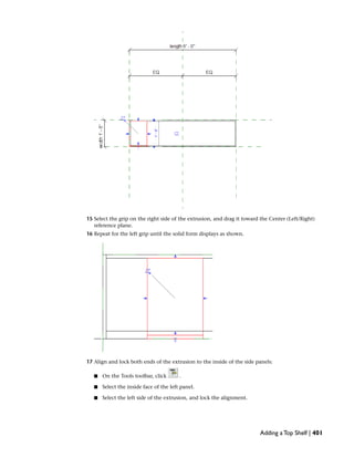
  • 1. 15 Select the grip on the right side of the extrusion, and drag it toward the Center (Left/Right) reference plane. 16 Repeat for the left grip until the solid form displays as shown. 17 Align and lock both ends of the extrusion to the inside of the side panels: ■ On the Tools toolbar, click . ■ Select the inside face of the left panel. ■ Select the left side of the extrusion, and lock the alignment. Adding a Top Shelf | 401
  • 2. ■ Select the inside face of the right panel. ■ Select the right side of the extrusion, and lock the alignment. 18 On the View toolbar, click (Default 3D View). 19 On the View Control Bar, click Model Graphics Style ➤ Shading with Edges. Flex the family 20 On the Design Bar, click Family Types. 21 In the Family Types dialog, for Name, select 60x18x60. 22 Click Apply. 23 Repeat for 36x12x36 and 72x18x48. 402 | Chapter 15 Creating a Bookcase (Furniture) Family
  • 3. 24 Click OK. 25 Proceed to the next exercise, Changing the Shape of the Side Panels on page 403. Changing the Shape of the Side Panels In this exercise, you change the shape of the bookcase side panels from rectangular to rounded. To accomplish this, you edit the panel sketches. In anticipation of future changes, you created the sketches in the Ref. Level view so that the side panels could be given a rounded face. Training File ■ Continue to use the family that you used in the previous exercise, Bookcase.rfa, or open training file ImperialFamiliesFurnitureBookcase_05.rfa. ■ If you are using the supplied training file, click File menu ➤ Save As. ■ In the left pane of the Save As dialog, click Training Files, and save the file as ImperialFamiliesFurnitureBookcase.rfa. Modify the left panel 1 In the Project Browser, under Floor Plans, double-click Ref. Level. 2 Select the left panel, and on the Options Bar, click Edit. 3 On the Design Bar, click Modify. Changing the Shape of the Side Panels | 403
  • 4. 4 Select the left vertical line of the panel sketch, and press DELETE. 5 Replace the deleted line with a rounded panel: ■ On the Design Bar, click Lines. ■ On the Options Bar, click (Arc passing through three points). ■ In the location where you deleted the panel line, select the top endpoint. ■ Select the bottom endpoint. ■ Click to place the arc. ■ Modify the arc dimension to 2'. 6 On the Design Bar, click Modify. 7 Select the arc, and on the Options Bar, click (Element Properties). 8 In the Element Properties dialog, under Graphics, select Center Mark Visible, and click OK. Displaying the center mark allows you to dimension to the center of the circle. 9 On the Design Bar, click Dimension. 10 Dimension the Left reference plane and the center of the circle. This ensures that the arc center will stay at a fixed distance from the Left reference plane. 404 | Chapter 15 Creating a Bookcase (Furniture) Family
  • 5. Modify the right panel 11 Using the same method, create a rounded panel on the right side of the bookcase. 12 On the Design Bar, click Finish Sketch. 13 On the View toolbar, click (Default 3D View). 14 Proceed to the next exercise, Creating and Assigning Subcategories on page 406. Changing the Shape of the Side Panels | 405
  • 6. Creating and Assigning Subcategories In this exercise, you add a number of subcategories to the bookcase family so you can assign materials to its individual components, such as the shelves, door, base plate, panels, and top. After you create the subcategories, you assign each piece of the bookcase geometry to one of the subcategories. Later in this tutorial, you apply different materials to each subcategory, allowing you to vary the materials that you apply to each component of the bookcase. Training File ■ Continue to use the family that you used in the previous exercise, Bookcase.rfa, or open training file ImperialFamiliesFurnitureBookcase_06.rfa. ■ If you are using the supplied training file, click File menu ➤ Save As. ■ In the left pane of the Save As dialog, click Training Files, and save the file as ImperialFamiliesFurnitureBookcase.rfa. Create subcategories in the Furniture category 1 Click Settings menu ➤ Object Styles. The Object Styles dialog displays. In the next steps, you add subcategories under the main Furniture category. Later in this tutorial, you will use this dialog to specify default materials for each subcategory that you create. 2 In the Object Styles dialog, on the Model Object tab, under Category, select Furniture. 3 Under Modify Subcategories, click New. 4 In the New Subcategory dialog, for Name, enter Base, and click OK. 5 Using the same method, create additional subcategories: ■ Top ■ Panels ■ Shelves ■ Door 6 When you finish creating subcategories, click OK. Assign solid forms to the corresponding subcategories 7 While pressing CTRL, select the side and back panels of the bookcase. 406 | Chapter 15 Creating a Bookcase (Furniture) Family
  • 7. On the Options Bar, click (Element Properties). 8 In the Element Properties dialog, under Identity Data, for Subcategory, select Panels, and click OK. 9 On the Design Bar, click Modify. 10 Using the same method, assign the corresponding subcategory to the top and the base of the bookcase. Although you created Door and Shelves categories, you have not created the door and shelf geometry. You will create and assign them in subsequent exercises. 11 Proceed to the next exercise, Adding Shelves on page 407. Adding Shelves In this exercise, you add 3 shelves to the bookcase family. You create the shelves by sketching multiple closed loops. You then apply parameters to control the shelf spacing. Adding Shelves | 407
  • 8. Training File ■ Continue to use the family that you used in the previous exercise, Bookcase.rfa, or open training file ImperialFamiliesFurnitureBookcase_07.rfa. ■ If you are using the supplied training file, click File menu ➤ Save As. ■ In the left pane of the Save As dialog, click Training Files, and save the file as ImperialFamiliesFurnitureBookcase.rfa. Sketch the shelves 1 In the Project Browser, under Elevations, double-click Front. 2 On the Design Bar, click Solid Form ➤ Solid Extrusion. 3 On the Options Bar, click (Rectangle). 4 Draw 3 stepped rectangles as shown. 5 Align and lock the left edges: ■ On the Tools toolbar, click (Align). ■ Select the left edge of the bottom rectangle, and then the left edge of the rectangle above. ■ Lock the alignment. ■ Select the left edge of the bottom rectangle, and then the left edge of the top rectangle. 408 | Chapter 15 Creating a Bookcase (Furniture) Family
  • 9. ■ Lock the alignment. 6 Repeat the process for the right edges of the rectangles. 7 Align and lock the bottom shelf edges with the inside face of the side panels: ■ On the Tools toolbar, click . ■ Select the reference plane at the top of the base, select the bottom edge of the lowest rectangle, and lock the alignment. Apply the panel_thickness parameter to the shelves 8 On the Design Bar, click Dimension. 9 Place individual dimensions (not a string) as shown to control shelf thickness and spacing. Adding Shelves | 409
  • 10. 10 Select the dimensions controlling the thickness of the shelf sketches, and apply the panel_thickness parameter. Create and apply maximum and minimum shelf spacing parameters 11 Select the dimension between the bottom and middle shelves. 12 On the Options Bar, for Label, click <Add parameter>. 13 In the Parameter Properties dialog, under Parameter Name, enter shelf_maximum_spacing, and click OK. 14 On the Design Bar, click Modify. 15 Select the dimension between the middle and top shelves, and create a shelf_minimum_spacing parameter. 410 | Chapter 15 Creating a Bookcase (Furniture) Family
  • 11. 16 On the Design Bar, click Extrusion Properties. 17 In the Element Properties dialog: ■ Under Constraints, for Extrusion End, enter 1'. This is a temporary value as you will later constrain the shelves to the back panel. ■ Click OK. Finish the shelves 18 On the Design Bar, click Finish Sketch. 19 In the Project Browser, under Floor Plans, double-click Ref. Level. 20 Select the shelf. 21 Drag and lock the sides of the shelf to the inside faces of the side panels. 22 Drag the top grip up and lock the edge of the shelf to the inside of the back panel. 23 On the View toolbar, click (Default 3D View). Adding Shelves | 411
  • 12. Flex the family 24 On the Design Bar, click Family Types. 25 In the Family Types dialog, for Name, verify 72x18x48 is selected. 26 Under Other, for shelf_minimum_spacing, enter 6''. 27 For shelf_maximum_spacing, enter 1'. 28 Click Apply. 29 For Name, select 60x18x60. 30 Under Other, for shelf_minimum_spacing, enter 6''. Shelf spacing can be specified with default values for each family type. 31 For shelf_maximum_spacing, enter 1'. 32 Click Apply. 412 | Chapter 15 Creating a Bookcase (Furniture) Family
  • 13. 33 For Name, select 36x12x36. 34 Under Other, for shelf_minimum_spacing, enter 4''. 35 For shelf_maximum_spacing, enter 4''. 36 Click Apply. 37 For Name, select 72x18x48, and click OK. Assign the Shelves subcategory 38 On the Design Bar, click Modify. 39 Select the shelves, and click (Element Properties). 40 In the Element Properties dialog, under Identity Data, for Subcategory, select Shelves. 41 Click OK. 42 Proceed to the next exercise, Adding an Enclosure Panel on page 413. Adding an Enclosure Panel In this exercise, you add a vertical enclosure panel to the top shelf of the bookcase. Adding an Enclosure Panel | 413
  • 14. In the next exercise, you create a door to complete the enclosure. Training File ■ Continue to use the family that you used in the previous exercise, Bookcase.rfa, or open training file ImperialFamiliesFurnitureBookcase_08.rfa. ■ If you are using the supplied training file, click File menu ➤ Save As. ■ In the left pane of the Save As dialog, click Training Files, and save the file as ImperialFamiliesFurnitureBookcase.rfa. Create a reference plane for the vertical enclosure panel 1 In the Project Browser, under Elevations, double-click Front. 414 | Chapter 15 Creating a Bookcase (Furniture) Family
  • 15. 2 On the Design Bar, click Ref Plane. 3 Sketch a vertical reference plane between the left and center planes. 4 On the Design Bar, click Modify. 5 Select the reference plane, and on the Options Bar, click (Element Properties). 6 In the Element Properties dialog, under Identity Data, for Name, enter Enclosure. 7 Click OK. Create a parameter to control the enclosure length 8 On the Design Bar, click Dimension. 9 Select the Left reference plane. 10 Select the Enclosure reference plane. 11 Click to place the dimension. 12 On the Design Bar, click Modify. Adding an Enclosure Panel | 415
  • 16. 13 Select the dimension you just placed, and on the Options Bar, for Label, select <Add parameter>. 14 In the Parameter Properties dialog, under Parameter Data, for Name, enter enclosure_length, and click OK. 15 On the Design Bar, click Family Types. 16 In the Family Types dialog, under Other, for enclosure_length, enter 2', and click Apply. 17 Apply the same value for enclosure_length to all the family types. 18 For Name, select 72x18x48, and click OK. Sketch the enclosure panel 19 On the Design Bar, click Solid Form ➤ Solid Extrusion. 20 On the Options Bar, click (Rectangle). 21 Draw the sketch clear of reference planes. 416 | Chapter 15 Creating a Bookcase (Furniture) Family
  • 17. 22 On the Tools toolbar, click (Align). 23 Select the Enclosure reference plane. 24 Select the left edge of the rectangle, and lock the alignment. 25 Select the underside of the bookcase top. 26 Select the top of the rectangle, and lock the alignment. Adding an Enclosure Panel | 417
  • 18. 27 Select the top face of the top shelf. 28 Select the bottom line of the rectangle, and lock the alignment. 29 Dimension between the Enclosure reference plane and the right edge of the rectangle: ■ On the Design Bar, click Dimension. ■ Select the Enclosure reference plane. ■ Select the right edge of the sketch. 418 | Chapter 15 Creating a Bookcase (Furniture) Family
  • 19. ■ Click to place the dimension. Add the panel_thickness parameter 30 On the Design Bar, click Modify. 31 Select the dimension that you just placed. 32 On the Options Bar, for Label, select panel_thickness. 33 On the Design Bar, click Finish Sketch. Adding an Enclosure Panel | 419
  • 20. Align the panel 34 In the Project Browser, under Floor Plans, double-click Ref. Level. 35 Select the panel. 36 Drag the top grip to align with the inside face of the back panel and lock the alignment. 37 Drag the bottom grip to align with the inside face of the top shelf. 420 | Chapter 15 Creating a Bookcase (Furniture) Family
  • 21. 38 On the View toolbar, click (Default 3D View). 39 Assign a subcategory to the panel: ■ Select the panel, and on the Options Bar, click (Element Properties). ■ In the Element Properties dialog, under Identity Data, for Subcategory, select Panels, and click OK. ■ Press ESC. 40 Proceed to the next exercise, Adding a Door on page 421. Adding a Door In this exercise, you add a door with a circular opening and a glass panel that adjusts to fit the enclosure. The same parameter that positions the vertical panel controls the door width. Adding a Door | 421
  • 22. Training File ■ Continue to use the family that you used in the previous exercise, Bookcase.rfa, or open training file ImperialFamiliesFurnitureBookcase_09.rfa. ■ If you are using the supplied training file, click File menu ➤ Save As. ■ In the left pane of the Save As dialog, click Training Files, and save the file as ImperialFamiliesFurnitureBookcase.rfa. Use concentric rectangles to create the door 1 In the Project Browser, under Elevations, double-click Front. 2 On the Design Bar, click Solid Form ➤ Solid Extrusion. 3 Click Set Work Plane. 4 In the Work Plane dialog, under Specify a new Work Plane, verify that Name and Reference Plane: Front are selected. 5 Click OK. 6 On the Options Bar, click (Rectangle). 7 Sketch 2 concentric rectangles as shown. The inner sketch will be interpreted as a void by the software. 422 | Chapter 15 Creating a Bookcase (Furniture) Family
  • 23. 8 On the Design Bar, click Modify. 9 On the Tools toolbar, click (Align). 10 Align and lock the 4 edges of the outer sketch: ■ Align and lock the left edge to the inside of the side panel. ■ Align the top edge to the bottom of the downturn (top shelf). ■ Align the right edge to the outside face of the vertical panel. ■ Align the bottom edge to the top face of the shelf. 11 On the View Control Bar, click the current scale, and select 3''=1'-0''. 12 Dimension the door sketch to locate the opening: ■ On the Design Bar, click Dimension. ■ Move the cursor over one of the lines of the outer sketch, press TAB until it highlights, and select it. Adding a Door | 423
  • 24. ■ Move the cursor to the parallel line of the inner sketch, select the line, and click to place the dimension. ■ Using the same method, dimension the remaining sketch lines. 13 On the Design Bar, click Modify. 14 Select the inner sketch lines individually and adjust each offset distance to 3''. 15 On the Design Bar, click Extrusion Properties. 16 In the Element Properties dialog, under Constraints, for Extrusion End, click . 424 | Chapter 15 Creating a Bookcase (Furniture) Family
  • 25. 17 In the Associate Family Parameter dialog, under Existing family parameters of compatible type, select panel_thickness. 18 Click OK twice. 19 On the Design Bar, click Finish Sketch. Draw a solid form for the door glass 20 On the Design Bar, click Solid Form ➤ Solid Extrusion. 21 Click Set Work Plane. 22 In the Work Plane dialog, under Specify a new Work Plane, verify that Name and Reference Plane: Front are selected. 23 Click OK. 24 On the Options Bar, click . 25 Sketch a rectangle directly on top of the rectangle that represents the void (the inner rectangle sketch). 26 Lock each line. Because you sketched the rectangle on top of the other, alignment between the rectangles is assumed. This is a fast way to align elements. It is only applicable where there are not multiple superimposed faces or reference planes. 27 With the glass sketch still selected, on the Design Bar, click Extrusion Properties. 28 In the Element Properties dialog: ■ Under Constraints, for Extrusion End, enter 1/2''. ■ For Extrusion Start, enter 1/4''. ■ Click OK. 29 On the Design Bar, click Finish Sketch. 30 In the Project Browser, under Floor Plans, double-click Ref. Level. 31 Confirm that the glass displays as shown. Adding a Door | 425
  • 26. You can edit the extrusion properties if the beginning and end of the extrusion need to be adjusted. 32 On the View toolbar, click (Default 3D View). The glass now displays as a solid form. Later in this tutorial, you will apply a glass material to the form. 33 Assign a subcategory to the door: ■ Select the door, and on the Options Bar, click (Element Properties). ■ In the Element Properties dialog, under Identity Data, for Subcategory, select Door, and click OK. ■ Press ESC. Create a circular opening 34 In the Project Browser, under Elevations, double-click Front. 35 On the Design Bar: ■ Click Void Form ➤ Void Extrusion. 426 | Chapter 15 Creating a Bookcase (Furniture) Family
  • 27. ■ Click Set Work Plane. 36 In the Work Plane dialog, under Specify a new Work Plane, verify that Name and Reference Plane: Front are selected. 37 Click OK. 38 On the Options Bar, click , and click (Circle). 39 Sketch a circle with a 1'' radius at the top right corner of the door. 40 On the Design Bar, click Modify. 41 Select the circle, and on the Options Bar, click (Element Properties). 42 In the Element Properties dialog, under Graphics, select Center Mark Visible, and click OK. 43 On the Design Bar, click Dimension. 44 Add 2 dimensions and position the center of the circle 1-1/4'' from the top edges of the glass opening. 45 On the Design Bar, click Extrusion Properties. 46 In the Element Properties dialog: ■ Under Constraints, for Extrusion End, enter 1''. ■ For Extrusion Start, enter 0. You use a value greater than the thickness of the door. Adding a Door | 427
  • 28. 47 On the Design Bar, click Finish Sketch. Verify that you created a solid void extrusion that starts on the Front reference plane and ends beyond the door. 48 On the View toolbar, click (Default 3D View). 49 Proceed to the next exercise, Managing Visibility on page 429. 428 | Chapter 15 Creating a Bookcase (Furniture) Family
  • 29. ManagingVisibility In this exercise, you specify the visibility of the bookcase family in different views. When you add bookcase instances to plan views, you want to make sure that a 2D symbolic linework representation of the bookcase displays, and not a hidden line representation of the more complex 3D bookcase. By specifying the appropriate visibility settings in each view, you reduce the regeneration time of the bookcase element in your projects. Training File ■ Continue to use the family that you used in the previous exercise, Bookcase.rfa, or open training file ImperialFamiliesFurnitureBookcase_10.rfa. ■ If you are using the supplied training file, click File menu ➤ Save As. ■ In the left pane of the Save As dialog, click Training Files, and save the file as ImperialFamiliesFurnitureBookcase.rfa. Create symbolic lines for detail levels 1 In the Project Browser, under Floor Plans, double-click Ref. Level. 2 On the Design Bar, click Symbolic Lines. 3 On the Options Bar: ■ Clear Chain. ■ Click , and click (Arc passing through three points). 4 Using the Line and Arc tools, create a closed sketch as shown, clear of the existing bookcase geometry. 5 On the Options Bar, click (Align). 6 Align the sketch in the following order: ■ Align the top of the sketch to the Back reference plane. ■ Align both arcs to the arced side faces. ■ Align the bottom line to the Front reference plane. The order in which you align the sketch geometry is important because you need to establish the relationships between the connected sides of the sketch. 7 On the Design Bar, click Modify, and select all of the bookcase geometry, including the sketch that you just aligned. 8 On the Options Bar, click (Filter). 9 In the Filter dialog, click Check None. 10 Select Lines (Furniture), and click OK. ManagingVisibility | 429
  • 30. 11 On the Options Bar, click Visibility. 12 In the Family element visibility settings dialog, under Detail Levels, verify that Coarse, Medium, and Fine are selected, and click OK. The outline symbolic linework will display at all detail levels. 13 On the Design Bar, click Symbolic Lines. 14 Draw and constrain a symbolic line on the inside face of the back panel and on the inside face of both side panels. 15 While pressing CTRL, select the 3 lines. 16 On the Options Bar, click Visibility. 17 In the Family element visibility settings dialog, under Detail Levels, clear Coarse. The additional 3 symbolic lines will display in the Medium and Fine detail levels. You still need to ensure that the 3D geometry does not show in plan views where it could increase regeneration time. 18 Click OK. 19 On the View toolbar, click (Default 3D View). 20 Select all of the 3D geometry. The symbolic lines only display parallel to the view in which they were drawn, so they are not available for selection in the 3D view. 21 On the Options Bar, click Visibility. 22 In the Family Element Visibility Settings dialog: ■ Under View Specific Display, clear Plan/RCP. NOTE Furniture families can not be cut in Plan/RCP. Families such as windows or doors would have this option. ■ Click OK. The 3D model will not display in plan views. This only becomes clear to you when you see the family in a project. 23 On the Design Bar, click Modify. 24 Open the i_art_gallery.rvt project, and open the Level 1 floor plan. 25 Open Bookcase.rfa, and on the Design Bar, click Load into Projects. 430 | Chapter 15 Creating a Bookcase (Furniture) Family
  • 31. 26 Click Component. 27 Place the bookcase, and test its display in coarse, medium, and 3D views. The symbolic linework shown in plan views does not hide a pattern on a floor, so you must also add a masking region to the bookcase family. You want the model to display as shown when viewed at medium or fine detail on a floor with a material pattern. 28 Proceed to the next exercise, Adding a Masking Region on page 431. Adding a Masking Region In this exercise, you create a masking region to ensure that the bookcase hides any floor materials on which it is placed in a plan view. Training File ■ Continue to use the family that you used in the previous exercise, Bookcase.rfa, or open training file ImperialFamiliesFurnitureBookcase_11.rfa. ■ If you are using the supplied training file, click File menu ➤ Save As. ■ In the left pane of the Save As dialog, click Training Files, and save the file as ImperialFamiliesFurnitureBookcase.rfa. Create a masking region 1 In the Project Browser, under Floor Plans, double-click Ref. Level. 2 Select all the bookcase geometry. 3 On the Options Bar, click (Filter). 4 In the Filter dialog, click Check None. 5 Select Lines (Furniture), and click OK. Adding a Masking Region | 431
  • 32. 6 On the View Control Bar, click Click Temporary Hide/Isolate ➤ Hide Category. This removes the lines from the view so you can more easily align the masking region to the geometry. 7 On the Design Bar, click Masking Region. 8 On the Options Bar, use (Line) and (Arc passing through three points) to create a closed sketch as shown, clear of the existing geometry. Align and constrain the masking region 9 On the Tools toolbar, click (Align). 10 Align and lock the masking region: ■ Align the top line to the Back reference plane. ■ Align both arcs to the arced side faces. ■ Align the bottom line to the Front reference plane. 11 On the Design Bar, click Finish Sketch. 12 On the View Control Bar, click Click Temporary Hide/Isolate ➤ Reset Temporary Hide/Isolate. 13 Proceed to the next exercise, Creating and Assigning Materials on page 432. Creating and Assigning Materials In this exercise, you create and apply materials to the components of the bookcase family: the base plate, the door, the glass panel in the door, the panels, the shelves, and the bookcase top. To apply materials to these different components, you apply them directly and by family subcategory. You begin by applying a glass material to the panel in the bookcase door. This panel is intended to be glass and is unlikely to change, so you apply it directly to the Material parameter of the panel in its Element Properties. 432 | Chapter 15 Creating a Bookcase (Furniture) Family
  • 33. Glass material applied to the bookcase door Next, you decide to apply a different material to each of the remaining components of the bookcase. When you create bookcases with the finished family, you also want to be able to apply a different material to each component and update all instances of the bookcase to reflect the material change. To accomplish this, you apply different materials to each of the family subcategories: Base, Door, Panels, Shelves, and Top. Changing the material that is applied to the Shelves subcategory will change the shelf material of all bookcases that you create with the Bookcase family. You can also create material parameters within a family to provide a list of alternate materials. The material can be unique within the bookcase. Material parameters are covered in the next exercise. Training File ■ Continue to use the family that you used in the previous exercise, Bookcase.rfa, or open training file ImperialFamiliesFurnitureBookcase_12.rfa. ■ If you are using the supplied training file, click File menu ➤ Save As. ■ In the left pane of the Save As dialog, click Training Files, and save the file as ImperialFamiliesFurnitureBookcase.rfa. Apply a glass material to the bookcase door 1 If necessary, on the View toolbar, click (Default 3D View), and zoom in to the door. 2 Select the solid form that represents the door glass. Creating and Assigning Materials | 433
  • 34. 3 On the Options Bar, click (Element Properties). 4 In the Element Properties dialog, under Materials and Finishes, for Material, click in the Value field, and click . 5 In the Materials dialog, under Materials, select Glass. 6 In the right pane, on the Graphics tab, review the Shading settings. The Glass material has a blue color and a Transparency value of 75%. 7 Click OK twice. 8 On the Design Bar, click Modify. The bookcase door glass displays as both blue and transparent in the project. After you apply a material in the Element Properties, you can only change it in the Family Editor. You cannot change it in an instance of the family in a project. TIP When creating proprietary furniture families, use this method to apply all the necessary furniture materials. The materials display in projects as designed and are not easily modified. 434 | Chapter 15 Creating a Bookcase (Furniture) Family
  • 35. Create new materials for the bookcase 9 Click Settings menu ➤ Materials. 10 In the Materials dialog, under Materials, select Default. 11 In the bottom left pane of the Materials dialog, click (Duplicate). 12 In the Duplicate Revit Material dialog, for Name, enter Bookcase_Base, and click OK. The new material displays in the Materials list. TIP Use a material naming convention like this one to group family materials under a common prefix (in this example, Bookcase). Materials applied to family components are loaded into a project with the family. 13 Using the same method, create the following bookcase materials by duplicating the Bookcase_Base material (keep the Materials dialog open when you’re finished creating materials): ■ Bookcase_Top ■ Bookcase_Panels ■ Bookcase_Shelves ■ Bookcase_Door Next, assign display properties and render appearances to each of the materials that you just created. Later, when you apply the material to a family component, the display properties determine the component color in shaded views. The render appearance determines the display of the component when it is rendered. Specify the material display properties and render appearances 14 In the Materials dialog, under Name, select Bookcase_Base. 15 On the Graphics tab, under Shading, click the color swatch. 16 In the Color dialog, select a brown color for the bookcase base, and click OK. This is usually similar in color to the render material and is useful in visually differentiating material assignments. Creating and Assigning Materials | 435
  • 36. 17 In the Materials dialog, click the Render Appearance tab. 18 Under Render Appearance Based On, click Replace. 19 In the Render Appearance Library, for Class, select Paint. 20 Select the Paint Brindle Glossy render appearance. 21 Click OK. 22 Using the same method, assign the following colors and render appearances to the other bookcase materials: Render AppearanceColorMaterial Paint Light Red GlossyRedBookcase_Door Paint Dark Cadet Blue GlossyBlue-greenBookcase_Panels Wood Birch Natural Medium GlossLight brownBookcase_Shelves Paint Brindle GlossyMedium brownBookcase_Top NOTE When you assign the Wood Birch Natural Medium Gloss render appearance to the shelves, notice that it contains a bitmap image to depict the wood grain. Materials with bitmap images like this one are visible only when you render an element in a project to which the material is applied. 23 Click OK. Next, apply the Bookcase materials to the corresponding family subcategories in order to apply them to the family components. Apply the bookcase materials to the Furniture subcategories 24 Click Settings menu ➤ Object Styles. 25 In the Object Styles dialog, on the Model Objects tab, under Category ➤ Furniture, select Base. 26 For Base, click in the Material field, and click . 27 In the Materials dialog, under Materials, select Bookcase_Base, and click OK. 28 Using the same method, assign the remaining bookcase materials to the corresponding subcategories: MaterialSubcategory Bookcase_DoorDoor Bookcase_PanelsPanels Bookcase_ShelvesShelves Bookcase_TopTop 29 Click OK. The bookcase family displays with the colors that you assigned to it. 30 Proceed to the next exercise, Creating a Material Parameter on page 437. 436 | Chapter 15 Creating a Bookcase (Furniture) Family
  • 37. Creating a Material Parameter In this exercise, you add a material parameter to the bookcase family. When you add bookcases to a project, this parameter gives you the option to change the door material for a single bookcase or for each type of bookcase that you create, independent of the material that is applied to the bookcase door by family subcategory. Training File ■ Continue to use the family that you used in the previous exercise, Bookcase.rfa, or open training file ImperialFamiliesFurnitureBookcase_13.rfa. ■ If you are using the supplied training file, click File menu ➤ Save As. ■ In the left pane of the Save As dialog, click Training Files, and save the file as ImperialFamiliesFurnitureBookcase.rfa. Add a material parameter to the Bookcase family 1 On the Design Bar, click Family Types. 2 In the Family Types dialog, under Parameters, click Add. Creating a Material Parameter | 437
  • 38. 3 In the Parameter Type dialog: ■ Under Parameters, for Name, enter door_finish. ■ Under Group Parameter under, select Materials and Finishes. ■ Under Type of Parameter, select Material. ■ Select Instance. By creating this parameter as an instance parameter, you will be able to choose different door finishes for each instance of the bookcase family that you place in a project. 4 Click OK twice. Apply the door_finish parameter to the door 5 Select the door, and click (Element Properties). 6 In the Element Properties dialog: ■ Under Materials and Finishes, for Material, click . ■ In the Associate Family Parameters dialog, for Existing family parameters of compatible type, select door_finish. 7 Click OK twice. 8 Save the bookcase family. Load the bookcase family into a new project 9 Click File menu ➤ New ➤ Project. 10 Name and save the new project, but do not close it. 11 Open Bookcase.rfa, and on the Design Bar, click Load into Projects. The new project displays. Place 3 instances of the bookcase family 12 On the Design Bar, click Component. 13 In the Type Selector, select a bookcase type, and place 3 bookcases of the same type in the project. 14 Click Modify. 15 On the View toolbar, click (Default 3D View). All 3 bookcases have materials applied to their components by family subcategory. 16 On the View Control Bar, click Model Graphics Style ➤ Shading with Edges. 438 | Chapter 15 Creating a Bookcase (Furniture) Family
  • 39. Vary the material applied to the bookcase doors 17 Select the middle bookcase. 18 On the Options Bar, click . 19 In the Element Properties dialog: ■ Under Other, for door_finish, click in the Value field, and click . ■ In the Materials dialog, under Materials, select Bookcase_Top. The same material applied to the top of the bookcase will be applied to the door. 20 Click OK twice. 21 Select the third bookcase. 22 Using the same method, apply the Bookcase_Shelves material to the door_finish parameter. Creating a Material Parameter | 439
  • 40. 23 Proceed to the next exercise, Controlling the Door Visibility on page 441. 440 | Chapter 15 Creating a Bookcase (Furniture) Family
  • 41. Controlling the DoorVisibility In this exercise, you add a visibility parameter to the bookcase family that lets you control whether a bookcase that you place in a project includes the glass panel door. The parameter controls the visibility of both the door and glass for each instance of the bookcase. When you create the parameter, you name it door_included so that its function is obvious. The parameter offers a yes/no selection when you view the properties of the bookcase door and glass. You choose yes to display the door and glass, or no to turn their visibility off. Training File ■ Continue to use the family that you used in the previous exercise, Bookcase.rfa, or open training file ImperialFamiliesFurnitureBookcase_14.rfa. ■ If you are using the supplied training file, click File menu ➤ Save As. ■ In the left pane of the Save As dialog, click Training Files, and save the file as ImperialFamiliesFurnitureBookcase.rfa. Add a parameter to control the door visibility 1 On the Design Bar, click Family Types. 2 In the Family Types dialog: ■ Under Parameters, click Add. ■ In the Parameter Properties dialog, under Parameter Data, for Name, enter door_included. ■ Under Group parameter under, select Materials and Finishes. ■ Under Type of Parameter, select Yes/No. The parameter will have a yes/no option for visibility. ■ Select Instance so that even with multiple instances of the same bookcase, you can decide which display with doors. 3 Click OK twice. Controlling the DoorVisibility | 441
  • 42. Associate the parameter with the door 4 In the drawing area, select the bookcase door. 5 On the Options Bar, click (Element Properties). 6 In the Element Properties dialog: ■ Under Graphics, for Visible, click . ■ In the Associate Family Parameters dialog, under Existing family parameters of compatible type, select door_included. 7 Click OK twice. Associate the parameter with the door glass 8 In the drawing area, select the glass in the door. 9 On the Options Bar, click . 10 In the Element Properties dialog: ■ Under Graphics, for Visible, click . ■ In the Associate Family Parameters dialog, under Existing family parameters of compatible type, select door_included. 11 Click OK twice. Add bookcases to a project 12 Click File menu ➤ New ➤ Project. 13 Name and save the new project, but do not close it. 14 Open Bookcase.rfa, and on the Design Bar, click Load into Projects. The new project displays. 15 On the Design Bar, click Component. 16 In the Type Selector, select Bookcase: 72x18x48, and add a bookcase to the project. 17 Using the same method, add a 60x18x60 and a 36x12x36 bookcase to the project. 18 Click Modify. Test the visibility of the door and glass in the project 19 On the View toolbar, click (Default 3D View). 442 | Chapter 15 Creating a Bookcase (Furniture) Family
  • 43. 20 Select the 60x18x60 bookcase. 21 On the Tools toolbar, click (Copy). 22 Drag the cursor forward, and click to create a copy. 23 Select the copy, and on the Options Bar, click . 24 In the Element Properties dialog: ■ Under Materials and Finishes, clear door_included. ■ Click OK. The bookcase door and glass no longer display in the copy of the bookcase. 25 Proceed to the next exercise, Creating a Type Catalog on page 444. Controlling the DoorVisibility | 443
  • 44. Creating aType Catalog In this exercise, you create a type catalog for the Bookcase family. A type catalog is a dialog that displays when you load a family into a project. It lists all the types in the family, allowing you to select and load only the types that the current project requires. Bookcase family type catalog To create a type catalog, you create an external text file that contains the parameters and parameter values that create the different types in the family. You place this file in the location of the family file. When you load the family, the type catalog displays. Type catalogs are most useful with large families, such as steel sections, that contain many types. Selecting and loading only the types that you need for a project helps keep the project file size smaller. BEST PRACTICE Create type catalogs for families that contain 6 or more types. Training File ■ Continue to use the family that you used in the previous exercise, Bookcase.rfa, or open training file ImperialFamiliesFurnitureBookcase_15.rfa. ■ If you are using the supplied training file, click File menu ➤ Save As. ■ In the left pane of the Save As dialog, click Training Files, and save the file as ImperialFamiliesFurnitureBookcase.rfa. Create a new type catalog file 1 Open Microsoft® Notepad. NOTE Although you use Notepad to create the type catalog in this exercise, you can use any available text editor. 2 Click File menu ➤ Save As. 3 Save the file as Bookcase.txt in the same location that you saved Bookcase.rfa. The type catalog must have the same name as the family. Enter first line of the type catalog file 4 On the first line in the text file, enter: ,length##length##inches 5 On the same line, at the end of the previous text, enter: ,width##length##inches 6 On the same line, at the end of the previous text, enter: 444 | Chapter 15 Creating a Bookcase (Furniture) Family
  • 45. ,height##length##inches The first line should now read: ,length##length##inches,width##length##inches,height##length##inches Enter the second line of the type catalog file 7 Specify the name and dimensions of the first type: 36x12x36,36,12,36 The family type name will display as 36x12x36, and the values that are delimited by commas display in the same order as they are in the first line of the file. 8 Add the 2 remaining types on separate lines: 60x18x60,60,18,60 72x18x48,72,18,48 Your completed type catalog should look like this: 9 Save and close the type catalog. Load bookcase types into a project with the type catalog 10 Open i_art_gallery.rvt, and open the Level 1 floor plan. 11 On the Design Bar, click Component. 12 On the Options Bar, click Load. 13 In the Open dialog, under Look in, navigate to the location where you saved Bookcase.rfa, select it, and click Open. The type catalog displays, listing the 3 bookcase types. 14 In the Specify Types dialog, under Types, select 36x12x36, and click OK. 15 In the Type Selector, notice that only the single type that you selected was loaded into the project. 16 Add a 36x12x36 bookcase to the art gallery project. Creating a Type Catalog | 445
  • 46. 446
  • 47. Using Reference Lines in Families In this tutorial, you use reference lines to create portions of 2 different families. Reference lines are similar in use to reference planes in that they help to create the parametric family skeleton that you reference when you create family geometry. However, you use them specifically to create and control the angular dimensions of a family. In the following exercises, you create a bookcase door and a seat back, both with adjustable angles. Bookcases featuring doors with varying swing angles Chair with adjustable seat back 16 447
  • 48. To create the adjustable angle for the door or seat back, you begin by constraining one end of the reference line and leaving the other end free. You then sketch the door or seat back geometry, and constrain it to the reference line. When the sketch is complete, you create a parameter that controls the angle between the reference line and a reference point. When you assign this parameter different values, the door swings or the seat back adjusts. Creating a Bookcase Door with a Reference Line In this exercise, you use a reference line to add a door with an adjustable swing to a bookcase family. The family contains several types (sizes), and the door must adjust in size and length to accommodate each type. Bookcases featuring doors with varying swing angles To create a hinge on which the door swings, you constrain one end of the reference line to the bookcase. Reference line for door swing After the reference line is in place, you create the solid door geometry and constrain it to the reference line. By creating a door angle parameter, you can adjust the swing angle of the door. 448 | Chapter 16 Using Reference Lines in Families
  • 49. When the door is complete, you add several bookcase types to a project, test the door swing angle, and change the material of the door. Open the bookcase family and specify a new work plane 1 Click File menu ➤ Open. 2 In the left pane of the Open dialog, click Training Files, and open ImperialFamiliesFurnitureBookcase with Door.rfa. A view of the bookcase, minus the door, displays. 3 In the Project Browser, under Floor Plans, double-click Ref. Level. 4 Zoom in to the top of the bookcase. 5 Click Tools menu ➤ Work Plane ➤ Set Work Plane. 6 In the Work Plane dialog: ■ Under Specify a new Work Plane, for Name, select Reference Plane: Top. ■ Click OK. Sketch an angled reference line 7 On the Design Bar, click Reference Lines. 8 Draw the reference line at a 45 degree angle: ■ Specify the start point of the line. The precise point is not necessary, as you constrain this point to the hinge location in a later step. Creating a Bookcase Door with a Reference Line | 449
  • 50. ■ Move the cursor diagonally down to the right, until a 45 degree angle displays. ■ When the cursor is near the vertical enclosure reference plane, select an endpoint for the line. Notice that the reference line displays as a solid green line to differentiate it from a reference plane. Like reference planes, reference lines do not have a visibility property. ■ On the Design Bar, click Modify. ■ Select the reference line to view its endpoints. The reference line endpoints display as solid blue circles. Unlike reference planes, you can dimension to the reference line endpoints. Dimension the reference line 9 Place a dimension between the Left reference plane and the reference line endpoint: ■ On the Design Bar, click Dimension. ■ Select the Left reference plane. 450 | Chapter 16 Using Reference Lines in Families
  • 51. ■ Select the upper endpoint of the reference line. ■ Move the cursor up, and click to the right of the dimension to place it. Creating a Bookcase Door with a Reference Line | 451
  • 52. 10 Place a dimension between the Front reference plane and the reference line endpoint: ■ Select the Front reference plane. ■ Select the upper endpoint of the reference line. ■ Move the cursor to the left of the bookcase, and click to place the dimension. Later, you use these 2 dimensions to locate the hinge point of the reference line. 11 Place an angular dimension: ■ On the Options Bar, click (Angular). ■ Select the reference line. 452 | Chapter 16 Using Reference Lines in Families
  • 53. ■ Select the Front reference plane. ■ Move the cursor between the reference line and plane, and click to place the dimension. In the next steps, you use this angular dimension to control the door swing angle. Select the angular dimension and create a door swing parameter 12 On the Design Bar, click Modify. 13 Select the angular dimension that you just placed. 14 On the Options Bar, for Label, select Add parameter. 15 In the Parameter Properties dialog: ■ Under Parameter Data, for Name, enter door_angle. ■ Select Instance. Selecting instance ensures that the door swing angle can be adjusted for every instance of this bookcase family that you add to a project. Creating a Bookcase Door with a Reference Line | 453
  • 54. ■ Click OK. Assign a parameter to fix the hinged end of the reference line 16 Select the dimension between the Left reference plane and the reference line endpoint. 17 On the Options Bar, for Label, select panel_thickness. This length parameter is provided in the exercise file. 454 | Chapter 16 Using Reference Lines in Families
  • 55. 18 Using the same method, assign the panel_thickness parameter to the other dimension. This fixes the location of the end of the reference line (the hinge). Because the reference line is constrained and locked to one end of the bookcase, changing the value of the door_angle parameter causes the reference line to reposition, allowing you to vary the angle of the door swing. Assign a parameter to control the length of the reference line. 19 On the Design Bar, click Dimension. 20 Position the cursor over the upper end of the reference line, press TAB until the point displays, and click to select the point. NOTE The TAB key may have to be pressed several times to display the point. Creating a Bookcase Door with a Reference Line | 455
  • 56. 21 Repeat for the other end of the reference line, and place the dimension above the line. 22 On the Design Bar, click Modify. 23 Select the dimension. 24 On the Options Bar, click Label, and select enclosure_length. This is the same parameter used to position the vertical panel, so you are ensuring that the reference line length matches the length of the enclosure. The door is later created on the reference line so that the door length matches that of the enclosure. Flex the family to test the swing angle of the reference line 25 On the Design Bar, click Family Types. 26 In the Family Types dialog, under Other, for door_angle, enter 0. 27 Click OK. The reference line ''closes'' to 0 degrees. In the next steps, you create a door from a solid extrusion and constrain it to the reference line. After you constrain the door, adjusting the value of the door_angle parameter changes the door swing angle. Sketch a door on a reference plane associated with the reference line 28 On the View toolbar, click (Default 3D View). 29 Spin the bookcase to orient it as shown. NOTE The reference planes, reference lines (such as the one shown), and dimensions that you use to create the family do not display when you add family elements to a project. They are used in family creation to ensure precise placement of geometry. 456 | Chapter 16 Using Reference Lines in Families
  • 57. 30 On the Design Bar, click Solid Form ➤ Solid Extrusion. 31 On the Design Bar, click Set Work Plane. Reference lines, provide 4 planes on which you can sketch. The 2 end planes are not of interest in this situation. Your reference line has a plane parallel to the top, and another perpendicular to that plane. 32 In the Work Plane dialog: ■ Under Specify a new Work Plane, select Pick a Plane. ■ Click OK. 33 Move the cursor over the reference line, press TAB until the reference line plane displays as shown, and select it. 34 Sketch a rectangle clear of any existing geometry: ■ On the Options Bar, click (Rectangle). ■ For Depth, enter -1”. This is a temporary value for the depth of the extrusion. A negative value ensures that the sketch extrudes away from you when it is finished. NOTE Extrusion properties can be edited to change values for the beginning and end of an extrusion. Positive and negative numbers control the extrusion direction. Creating a Bookcase Door with a Reference Line | 457
  • 58. ■ Specify a point for the lower left corner of the rectangle, as shown. ■ Move the cursor diagonally up and to the right, and specify a point for the upper right corner of the rectangle. ■ On the Design Bar, click Finish Sketch. Flex the family to ensure the door extrusion swings with the reference line 35 On the Design Bar, click Family Types. 36 In the Family Types dialog: ■ Under Other, for door_angle, enter 45. ■ Click Apply, and click OK. 458 | Chapter 16 Using Reference Lines in Families
  • 59. Dimension and label the door thicknesses in plan view 37 In the Project Browser, under Floor Plans, double-click Ref. Level. 38 On the Design Bar, click Dimension. 39 Select the reference line. 40 Select the inside face of the door, move the cursor to the right, and click to place the dimension. 41 On the Design Bar, click Modify, and select the dimension that you just placed. 42 On the Options Bar, for Label, select panel_thickness. By assigning a parameter, you establish relationships in the family, and you allow values to be changed in a project. If you do not anticipate changes, you can simply draw geometry to the desired size. 43 Select the door. 44 Select the blue arrow grip for the face that is coincident with the reference line, and drag it away from the reference line. 45 Drag it back onto the reference line and lock it. Creating a Bookcase Door with a Reference Line | 459
  • 60. Flex the family again to ensure the door swings with the reference line 46 On the Design Bar, click Family Types. 47 In the Family Types dialog: ■ Under Other, for door_angle, enter 20. ■ Click Apply. The door swing should adjust to a 20 degree angle from the front of the bookcase. ■ For door_angle, enter 0. ■ Click Apply. The door swing should adjust to a 0 degree angle from the front of the bookcase, appearing to be closed. 460 | Chapter 16 Using Reference Lines in Families
  • 61. ■ For door_angle, enter 45. ■ Click Apply, and click OK. 48 Constrain the left door face to the hinge location: ■ Select the door to display its grips. ■ Select the upper left blue triangular grip, and drag it to the hinge location, as shown. ■ Click to lock the alignment. Creating a Bookcase Door with a Reference Line | 461
  • 62. 49 Using the same method, lock the right door face to the lower end of the reference line. 50 On the Design Bar, click Modify. Constrain the top and bottom of the door 51 In the Project Browser, under Elevations, double-click Front, and zoom to the top left corner of the bookcase. 52 Constrain the top and bottom of the door to the bookcase: ■ On the Tools toolbar, click (Align). ■ Select the line above the top of the door. This is the downturn for the bookcase top. ■ Select the top of the door. ■ Click to lock the alignment. 53 Using the same method, constrain the bottom of the door to the top face of the bookcase shelf, and lock the alignment. 462 | Chapter 16 Using Reference Lines in Families
  • 63. 54 On the View toolbar, click . Flex the family to ensure the door displays in the 3 bookcase types (sizes) 55 On the Design Bar, click Family Types. 56 In the Family Types dialog: ■ For Name, select 36x12x36. ■ Click Apply. Creating a Bookcase Door with a Reference Line | 463
  • 64. ■ For Name, select 60x18x60. ■ Click OK. Sketch a circular knob on the door 57 Spin the bookcase to view the front face of the door. 58 Zoom in to the top portion of the door. 59 On the Design Bar, click Solid Form ➤ Solid Extrusion. 60 On the Options Bar, for Depth, enter 2''. 61 On the Design Bar, click Set Work Plane. 464 | Chapter 16 Using Reference Lines in Families
  • 65. 62 In the Work Plane dialog: ■ Under Specify a new Work Plane, select Pick a Plane. ■ Click OK. 63 Move the cursor over the reference line, and press TAB until the front-facing reference line plane highlights, and select it. 64 Sketch the knob: ■ On the Options Bar, click , and click (Circle). ■ Specify a point approximately 4'' from the top right corner of the door. ■ Move the cursor out, until a 1'' radius displays, and click to create the knob sketch. 65 On the Design Bar, click Modify. Creating a Bookcase Door with a Reference Line | 465
  • 66. Position the knob on the door 66 Select the circle, and on the Options Bar, click (Element Properties). 67 In the Element Properties dialog: ■ Under Graphics, select Center Mark Visible. ■ Click OK. 68 Place 2 dimensions to locate the knob 4'' from the top and right door faces: ■ On the Design Bar, click Dimension. ■ Move the cursor over the top face of the door, press TAB until it highlights as shown, and select the face. ■ Select the circle center. 466 | Chapter 16 Using Reference Lines in Families
  • 67. ■ Move the cursor to the left, and click to place the dimension. ■ Using the same method, dimension from the left face of the door to the circle center. Place the dimension below the circle. 69 Locate the door knob: ■ On the Design Bar, click Modify. ■ Select the circle. ■ Select the top dimension value, enter 4'', and press ENTER. ■ Select the right dimension value, enter 4'', and press ENTER. 70 On the Design Bar, click Finish Sketch. Creating a Bookcase Door with a Reference Line | 467
  • 68. Flex the family to test the enclosure length parameter 71 On the Design Bar, click Family Types. 72 In the Family Types dialog: ■ Under Other, for enclosure_length, enter 12''. ■ Click OK. Flex the family to retest the enclosure length parameter 73 On the View toolbar, click . 74 On the Design Bar, click Family Types. 75 In the Family Types dialog: ■ For Name, select 36x12x36. ■ Under Other, for enclosure length, enter 18''. ■ Click OK. The door enclosure length adjusts as needed. 468 | Chapter 16 Using Reference Lines in Families
  • 69. 76 Click File menu ➤ Save. Next, you test the stability of the family by adding bookcase types to a new project and varying the door swing angle. Add a bookcase of all 3 sizes (types) to a new project 77 Create a new project: ■ Click File menu ➤ New Project. ■ In the New Project dialog, under Create new, select Project. ■ Under Template file, verify the second option is selected, and click Browse. In the left pane of the dialog, click Training Files, and open ImperialTemplatesdefault.rte. Click OK. 78 On the Design Bar, click Load into Projects. 79 On the View toolbar, click . Next, you place 3 bookcases from right to left, as shown. 80 On the Design Bar, click Component. 81 In the Type Selector, select Bookcase: 72x18x48. 82 Specify an insertion point in the project. 83 In the Type Selector, select Bookcase: 60x18x60. 84 Specify an insertion point in the project. 85 In the Type Selector, select Bookcase: 36x12x36. 86 Specify an insertion point in the project. 87 On the Design Bar, click Modify. Creating a Bookcase Door with a Reference Line | 469
  • 70. Assign a different swing angle to each bookcase door 88 Select the 72x18x48 bookcase, and click . 89 In the Element Properties dialog: ■ Under Other, for door_angle, enter 80. ■ Click OK. 90 Using the same method, change the door angle of the 60x18x60 bookcase to 60. 91 Using the same method, change the door angle of the 36x12x36 bookcase to 0. 92 Copy the 72x18x48 bookcase and place the copy clear of the other bookcases. 470 | Chapter 16 Using Reference Lines in Families
  • 71. 93 Select the copied bookcase. This is the second instance of the same bookcase type. 94 On the Options Bar, click . 95 In the Element Properties dialog: ■ Under Other, for door_angle, enter 20. ■ Click OK. You made the bookcase so any instance of any bookcase type can have a unique value for the door swing. 96 Save and close the new project. Creating a Bookcase Door with a Reference Line | 471
  • 72. Creating an Angled Chair Back with a Reference Line In this exercise, you create an adjustable angled seat back for a chair family. To control the seat back angle, you constrain the seat back geometry to a reference line. One endpoint of the reference line is constrained to the chair seat, while the other endpoint is free, creating a hinge between the seat and seat back. An angular parameter controls the reference line angle, which in turn controls the angle of the seat back that is constrained to it. After you create the chair back and test the adjustable angle, you create a bench type by widening the seat of the chair. 472 | Chapter 16 Using Reference Lines in Families
  • 73. Open the chair family 1 Click File menu ➤ Open. 2 In the left pane of the Open dialog, click Training Files, and open ImperialFamiliesFurnitureChair.rfa. A view of the chair, minus the angled back, displays. Add a reference line to control the angle of the seat back 3 In the Project Browser, under Elevations (Elevation 1), double-click Left. 4 Zoom in to the chair hinge. Creating an Angled Chair Back with a Reference Line | 473
  • 74. 5 On the Design Bar, click Reference Lines. 6 Specify the start point and endpoint of the reference line: ■ Move the cursor over the intersection of the 2 reference planes in the center of the circular hole. ■ Press TAB until the intersection displays, and select it. ■ Move the cursor up at a 45 degree angle until it is located near the vertical reference plane as shown, and click to specify the endpoint. 474 | Chapter 16 Using Reference Lines in Families
  • 75. 7 On the Design Bar, click Modify. Align and constrain the reference line to the hinge location 8 On the Tools toolbar, click (Align). 9 Select the vertical connect_plane2 reference plane. Creating an Angled Chair Back with a Reference Line | 475
  • 76. 10 Move the cursor over the endpoint of the reference line, press TAB until the endpoint displays, and click to select it. 11 Click to lock the alignment. 12 With the Align command still active, select the horizontal connect_plane reference plane. 13 Move the cursor to the endpoint of the reference line, press TAB until the endpoint displays, and select it. 476 | Chapter 16 Using Reference Lines in Families
  • 77. 14 Click . Create a parameter to control the angle of the seat back 15 Place an angular dimension between the horizontal connect_plane reference plane and the reference line: ■ On the Design Bar, click Dimension. ■ On the Options Bar, click (Angular). ■ Select the connect_plane reference plane. ■ Select the reference line. ■ Specify a point between the reference line and the bottom reference plane to place the dimension. Creating an Angled Chair Back with a Reference Line | 477
  • 78. ■ On the Design Bar, click Modify. 16 Label the dimension to create a parameter: ■ Select the angular dimension. ■ On the Options Bar, for Label, select Add parameter. ■ In the Parameter Properties dialog, under Parameter Data, for Name, enter angle_seat_back. ■ Verify Type is selected. ■ Click OK. The angle_seat_back parameter label displays on the dimension. Flex the family to test the angle_seat_back parameter 17 On the Design Bar, click Family Types. 18 In the Family Types dialog, under Other, for angle_seat_back, enter 90. 19 Click OK. The reference line repositions at a 90 degree angle from the connect_plane reference plane. 478 | Chapter 16 Using Reference Lines in Families
  • 79. Open an elevation view of the chair 20 In the Project Browser, under Elevations, double-click Front. Sketch the seat back 21 On the Design Bar, click Solid Form ➤ Solid Extrusion. 22 On the Design Bar, click Set Work Plane. 23 In the Work Plane dialog, under Specify a new Work Plane, select Pick a plane, and click OK. 24 Move the cursor over the reference line, press TAB until the reference line plane displays as shown, and select it. Creating an Angled Chair Back with a Reference Line | 479
  • 80. 25 Sketch a rectangle clear of the existing geometry: ■ On the Design Bar, verify Lines is selected. ■ On the Options Bar, click (Rectangle). ■ Specify a point above the chair geometry for the bottom right corner of the rectangle. Precise placement of the point is not necessary. ■ Move the cursor diagonally up, and specify a second point for the top left corner of the rectangle. Constrain the sides of the seat back 26 Place a dimension between the left side of the sketch and Left reference plane: ■ On the Design Bar, click Dimension. ■ Select the Left reference plane. ■ Select the left vertical side of the rectangle sketch, and click to the right of the dimension to place it. 480 | Chapter 16 Using Reference Lines in Families
  • 81. 27 Using the same method, dimension the Right reference plane and the right vertical side of the sketch. 28 Edit the dimensions: ■ On the Design Bar, click Modify. ■ Select the left vertical line of the sketch, and then select the dimension value. ■ Enter 3'', and press ENTER. Creating an Angled Chair Back with a Reference Line | 481
  • 82. 29 Using the same method, change the right dimension to 3''. 30 On the Design Bar, click Modify. 31 Align and constrain the seat back to the reference line: ■ On the Tools toolbar, click (Align). ■ Select endpoint of the reference line, as shown. ■ Select the bottom horizontal line of the rectangle. ■ Click . 482 | Chapter 16 Using Reference Lines in Families
  • 83. Create a parameter to control the height of the seat back 32 Dimension the height of the rectangle sketch: ■ On the Design Bar, click Dimension. ■ Select the bottom edge of the sketch. ■ Select the top edge of the sketch. ■ Move the cursor to the left, and click to place the dimension. ■ On the Design Bar, click Modify. 33 Label the dimension to create a parameter: ■ Select the dimension that you just placed. ■ On the Options Bar, for Label, select Add parameter. ■ In the Parameter Properties dialog, under Parameter Data, for Name, enter height_seat_back. ■ Click OK. 34 On the Design Bar, click Finish Sketch. Creating an Angled Chair Back with a Reference Line | 483
  • 84. Flex the family to ensure that the height of the seat back is adjustable 35 On the Design Bar, click Family Types. 36 In the Family Types dialog: ■ Under Other, for height_seat_back, enter 1'-6''. ■ Click OK. Center the seat back on the reference line for a side view 37 In the Project Browser, under Elevations, double-click Left. 38 Select the seat back to display blue triangular grips. 484 | Chapter 16 Using Reference Lines in Families
  • 85. 39 Select the grip on the front face of the seat back, and drag it to the right, clear of the reference line. Precise placement of the face is not necessary. 40 Create an equal dimension constraint: ■ On the Design Bar, click Dimension. ■ Select the back face of the seat back sketch. ■ Select the reference line (not the dashed reference plane). ■ Select the front face of the seat back sketch. ■ Move the cursor up, and click to place the dimension above the seat back. Creating an Angled Chair Back with a Reference Line | 485
  • 86. ■ If displays above the dimension, click it. The 2 segments of the dimension are now equal. Specify the thickness of the seat back as the same thickness as the chair sides 41 Dimension the thickness of the seat back: ■ On the Design Bar, click Dimension. ■ Select the front and back faces of the seat back. ■ Move the cursor up, and click to place the dimension above both the other dimension and the seat back. ■ On the Design Bar, click Modify. 42 Label the dimension to create a parameter: ■ Select the dimension that you just placed. ■ On the Options Bar, for Label, select side_thickness. ■ On the Design Bar, click Modify. The thickness of the side of the chair adjusts to 1'', the value currently set for the side_thickness parameter. 486 | Chapter 16 Using Reference Lines in Families
  • 87. Sketch a solid extrusion for the bottom of the seat back 43 Zoom in to the chair hinge. 44 On the Design Bar, click Solid Form ➤ Solid Extrusion. 45 On the Options Bar, click , and click (Circle). 46 At the center of the hinge hole, select the endpoint of the reference line at the intersection of the reference planes. 47 Specify a point on the hole perimeter. 48 On the Design Bar, click Finish Sketch. Creating an Angled Chair Back with a Reference Line | 487
  • 88. Sketch a solid extrusion for the seat back 49 In the Project Browser, under Elevations, double-click Front. 50 Select the cylindrical solid form. 51 Align and lock the left and right sides of the solid form to the vertical reference planes: ■ On the Tools toolbar, click . ■ Select the Left reference plane. ■ Select the left side of the solid form. ■ Click . ■ Select the Right reference plane. ■ Select the right side of the solid form. ■ Click . 52 On the View toolbar, click (Default 3D View). Test the angle of the seat back 53 On the Design Bar, click Family Types. 488 | Chapter 16 Using Reference Lines in Families
  • 89. 54 In the Family Types dialog: ■ Under Other, for angle_seat_back, enter 110. ■ Click OK. Create a new bench type to test the family 55 On the Design Bar, click Family Types. 56 In the Family Types dialog: ■ Under Family Types, click New. ■ In the Name dialog, for Name, enter bench 5', and click OK. ■ Under Dimension, for seat_width, enter 5'. ■ Click OK. 57 Click File menu ➤ Save, and close the project. Creating an Angled Chair Back with a Reference Line | 489
  • 90. 490
  • 92. 492
  • 93. Creating Shared Families In this tutorial, you create a window family using nested windows. The example illustrates how to create a family for common window combinations, such as custom window assembly. First, you create the window geometry and test how it behaves in a project. Then, you change the nested families in the window to shared and see how this change affects the window when it is loaded into a project. Skills used in this lesson include: ■ Creating a nested family from standard components ■ Adding family type parameters in order to control component type ■ Testing the family in a project ■ Tagging and scheduling windows ■ Specifying nested families as shared ■ Changing the family category in order to control scheduling Creating a Window Family with Nested Windows In this exercise, you create a window assembly family with 2 standard window families. You add family parameters to control the width and type of the windows. 17 493
  • 94. Open a window family template 1 Click File menu ➤ New ➤ Family. 2 In the Left pane of the New dialog, click Training Files, and open ImperialTemplatesWindow.rft. 3 Click File menu ➤ Save. 4 In the left pane of the Save As dialog, click Training Files, and save the file as ImperialFamiliesShared Window.rfa. Delete the existing opening in the template 5 Select the opening cut in the center of the wall. 6 Press DELETE. When you load the other windows as nested components, they cut the host, so the opening is not necessary. Load and place a fixed window 7 On the Design Bar, click Component. 8 Click Yes, to load a component. 9 In the left pane of the Open dialog, click Training Files, and open ImperialFamiliesWindowsFixed.rfa. 10 In the Type Selector, select Fixed : 36” x 48”. 11 Click the top face (exterior), near the center of the wall, to place the component. The fixed window is the center unit of the window assembly. NOTE When placing windows, make sure they are oriented in the wall correctly with respect to interior and exterior. The narrow part of the frame geometry is the exterior side of the window. After a window is placed, if it is not oriented correctly, you can use the flip control to switch the orientation. It may be helpful to change the display from coarse to medium or fine to see the exterior wall components. 12 Align and lock the fixed window to the center line of the family: ■ On the Tools toolbar, click (Align). ■ Select the Center (Left/Right) reference plane. ■ Select the vertical center line of the window. 494 | Chapter 17 Creating Shared Families
  • 95. ■ Click . Load and place the double hung window 13 On the Design Bar, click Component. 14 On the Options Bar, click Load. 15 In the left pane of the Open dialog, click Training Files, and open ImperialFamiliesWindowsDouble Hung.rfa. 16 In the Type Selector, select Double Hung : 24" x 48". 17 Place 2 windows, 1 on either side of the fixed window. Select the top face (exterior) as you place them. The double hung windows create the sides of the window assembly. 18 On the Design Bar, click Modify. 19 Align and lock the double hung windows to reference planes: ■ On the Tools toolbar, click (Align). ■ Select the Left reference plane, click the right edge of the left window, and click . ■ Select the Right reference plane, click the left edge of the right window, and click . Creating a Window Family with Nested Windows | 495
  • 96. 20 On the Design Bar, click Modify. The reference planes (aligned to the width of the center window) now control the placement of the center and side windows. Add family type labels to the side and center windows 21 Select the 2 double hung windows, and on the Options Bar, for Label, select Add parameter. You add family type parameters so that you can specify alternate window families or types. 22 In the Parameter Properties dialog, for Name, enter Side Window Type, for Group parameter under, select Construction, and click OK. 23 Select the center window, and on the Options Bar, for Label, select Add parameter. 24 In the Parameter Properties dialog, for Name, enter Center Window Type, for Group parameter under, select Construction, and click OK. The family type labels allow you to control the windows by changing types. Create family type parameters for the window widths 25 On the Design Bar, click Family Types. You create parameters for the center and side window widths. These parameters are used to calculate the overall opening, and to determine placement of the reference planes that control the position of the side windows. 26 In the Family Types dialog, under Parameters, click Add. 27 Add parameter properties: ■ For Name, enter Center Window Width. ■ For Group parameter under, select Dimensions. ■ For Type of Parameter, select Length. ■ Click OK. 28 Using the same method, add another Length parameter, named Side Window Width. Create family types for window configurations 29 In the Family Types dialog, under Construction, for Side Window Type, select Double Hung : 24" x 48". 30 In the Family Types dialog, under Construction, for Center Window Type, select Fixed : 36”x48”. 31 Under Dimensions, for Side Window Width, enter 2’, and for Center Window Width, enter 3'. NOTE You specify the side and center window width parameters manually because there is no way to pass the width information from a nested family (window unit) to the host family (window assembly). 32 Under Family Types, click New. 33 In the Name dialog, enter 24-36-24W x 48H, and click OK. 34 Under Family Types, click New. 35 In the Name dialog, enter 16-24-16W x 48H, and click OK. 36 Specify the family type parameters and the width parameters for the second family type: ■ For Name, verify that 16-24-16W x 48H is selected. ■ Under Construction, for Side Window Type, select Double Hung : 16'' x 48''. ■ For Center Window Type, select Fixed : 24'' x 48''. 496 | Chapter 17 Creating Shared Families
  • 97. ■ Under Dimensions, for Side Window Width, enter 16''. ■ For Center Window Width, enter 2'. ■ Click OK. Apply the Center Window Width parameter 37 Select the Width dimension, and on the Options Bar, for Label, select Center Window Width. (If necessary, move the Interior label so it doesn’t overlap the width label.) When you apply the Center Window Width parameter, the reference planes with the constrained side windows flex in position along the edge of the center window. 38 On the Design Bar, click Family Types. 39 In the Family Types dialog, under Dimensions, for Width ➤ Formula, enter Center Window Width + (Side Window Width*2). This formula adds the center window width and the 2 side window widths. The resulting value is the full width of the window assembly as it is reported in a schedule. 40 For Height, enter 4’, and click OK. This value must match the height of the individual window units because it displays in the schedule for the window assembly. 41 On the Standard toolbar, click (Default 3D View). Creating a Window Family with Nested Windows | 497
  • 98. 42 Click File menu ➤ Save. 43 Proceed to the next exercise, Using a Shared Family in a Project on page 498. Using a Shared Family in a Project Next, you place the window family into a project environment. Because you want the individual windows inside the window assembly to be scheduled as separate items, you change the nested windows to shared families. Test window assemblies in a project 1 Click Window menu ➤ Project1 - Floor Plan: Level 1. 2 On the Design Bar, click Wall. 3 Sketch a wall from left to right (approximately 24'). The top face of the wall is the exterior side. 4 On the Design Bar, click Modify. 5 Click Window menu ➤ Shared Window.rfa - 3D View: {3D}. 6 On the Design Bar, click Load into Projects. 7 If the Load into Projects dialog displays, select Project1, and click OK. The family is loaded into the new project. Place the family in the project 8 On the Design Bar, click Window. 9 Place 2 instances of the window into the project, one of each type: ■ In the Type Selector, verify that Shared Window : 24-36-24W x 48H is selected, and click the wall on the top face to place the window assembly. ■ In the Type Selector, select Shared Window : 16-24-16W x 48H, and click to place the smaller window assembly. ■ On the Design Bar, click Modify. 10 Zoom in to the 2 windows. Windows have been inserted and labeled as expected. NOTE The tag numbers are editable, either on the tag or in a schedule. 498 | Chapter 17 Creating Shared Families
  • 99. Create a window schedule 11 Click View menu ➤ New ➤ Schedule/Quantities. 12 In the New Schedule dialog, under Category, select Windows, and click OK. 13 In the Schedule Properties dialog, under Available fields, select Type Mark, and click Add. 14 Using the same method, add the following fields: ■ Width ■ Height ■ Family 15 With Family selected under Scheduled fields, click Move Up twice to reorder the fields, and click OK. There are 2 entries in the window schedule, listing the total width for each type of the window assembly. In order to schedule the individual window units within the assembly as separate items, you make the families shared. IMPORTANT Sharing families allows individual family instances that are loaded into another family to be counted and scheduled. Open the family for editing 16 In the Project Browser, under Floor Plans, double-click Level 1. 17 Select either window assembly, and on the Options Bar, click Edit Family. 18 In the confirmation dialog, click Yes to open Shared Window.rfa. 19 In the drawing area, select a side window and on the Options Bar, click Edit Family. 20 In the confirmation dialog, click Yes to open the double hung window for editing. Using a Shared Family in a Project | 499
  • 100. Make the families shared 21 Click Settings menu ➤ Family Category and Parameters. 22 In the Family Category and Parameters dialog, under Family Parameters, select Shared, and click OK. 23 On the Design Bar, click Load into Projects. 24 In the Load into Projects dialog, clear Project1, select Shared Window.rfa, and click OK. 25 In the Reload Family dialog, select Override parameter values of existing types, and click Yes. 26 Use the same method to make the center fixed window shared, and reload it into the Shared Window.rfa family. Reload the shared family into the project 27 On the Design Bar, click Load into Projects. 28 In the Load into Projects dialog, select Project1, and click OK. 29 In the Reload Family dialog, select Override parameter values of existing types, and click Yes. 30 In the Reload shared family dialog, verify that Family and Override parameter values of existing types are selected, and click OK. Tag windows in the window assembly 31 Select both window tags and move them away from the wall to leave space for window unit tags, and on the Design Bar, click Modify. 32 On the Drafting tab of the Design Bar, click Tag All Not Tagged. Now that the families have been shared, each window in the window assembly can be tagged. 33 In the Tag All Not Tagged dialog, under Category, select Window Tags, and click OK. 500 | Chapter 17 Creating Shared Families
  • 101. Open the window schedule 34 In the Project Browser, expand Schedules/Quantities, and double-click Window Schedule. Individual instances of the windows in the window assembly are included in the schedule. Again, depending on requirements and office standards, you may not want the overall window assembly to be displayed in the schedule. A schedule filter can be applied to filter the window assembly entries, or the hosting family category can be altered so that it is not included in the schedule. Modify the window assembly family category 35 Click Window menu ➤ Shared Window Family.rfa - 3D View: {3D}. 36 Click Settings menu ➤ Family Category and Parameters. 37 In the Family Category and Parameters dialog, under Family Category, select Generic Models, and click OK. When you change the category of the window from Window to Generic Models, the window is no longer included in the window schedule. 38 On the Design Bar, click Load into Projects. 39 In the Load into Projects dialog, select Project1, and click OK. 40 In the Reload Family dialog, click Yes to overwrite the existing family version. 41 In the warning message dialog, click OK. This message notifies you that the tags that had been previously placed will be deleted since the window assembly is no longer categorized as a window. 42 In the Project Browser, under Schedules/Quantities, double-click Window Schedule. The window assembly families are no longer reported on the window schedule. Using a Shared Family in a Project | 501
  • 102. 43 Right-click on the schedule and select View Properties. 44 In the Element Properties dialog, under Other, for Sorting/Grouping, click Edit. 45 In the Schedule Properties dialog, for Sort by, select Type Mark. 46 Click OK twice. 47 Close the project with or without saving it. 502 | Chapter 17 Creating Shared Families
  • 104. 504
  • 105. Creating a Complex Window Family In this tutorial, you create a complex window family from a basic template. The window is defined to be used in a cavity wall, with wall components that wrap to the window frame on both the interior and exterior of the wall. The window is composed of 2 window types: an operable casement window (width defined by the user) and a fixed window. In addition to creating the 3D geometry, you add symbolic lines to the family so that it displays cleanly in plan and elevation views. 18 505
  • 106. Casement swing display in elevation Casement swing display in plan Finally, you nest standard sill families into the window to be displayed and scheduled. 506 | Chapter 18 Creating a Complex Window Family
  • 107. Creating a Complex Wall Opening In this lesson, you open a file based on a window template and create a complex opening for the window. You delete the existing opening in the wall, and create a new opening by cutting the wall with a series of voids. You use a series of voids rather than a single sketch because the void sizes are different values. Complex wall opening with interior and exterior wrap Skills used in this lesson: ■ Creating void geometry ■ Using the Cut Geometry tool ■ Adding parameters to control wrap values, where wall components will overlap, and the depth of the window frame. ■ Adding family types for window sizes ■ Testing the family in a project ■ Modifying properties to define wall closure and wrap options Creating aVoid to Cut the Exterior Wall Face In this exercise, you create a void extrusion to cut an opening in the exterior wall face. Open the family file 1 Click File menu ➤ Open. 2 In the left pane of the New dialog, click Training Files, and open ImperialFamiliesWindowsComplex_Window_Start.rfa. 3 Click File menu ➤ Save As. Creating a Complex Wall Opening | 507
  • 108. 4 In the left pane of the Save As dialog, click Training Files, and save the file as ImperialFamiliesComplex_Window.rfa. Modify the size of the host wall 5 In the drawing area, select the wall, and on the Options Bar, click (Properties). You alter the size of the host wall in the family template because this family will be used in a cavity wall, which is typically thicker than a standard wall. By making the host wall in the template thicker, it will also provide more room to create the reference planes needed when you make the complex opening. 6 In the Element Properties dialog, click Edit/New. 7 In the Type Properties dialog, under Construction, for Structure, click Edit. 8 In the Edit Assembly dialog, for Layer 2, click in the Thickness field, and enter 12''. 9 Click OK 3 times. 10 On the Design Bar, click Modify. 11 Select the bottom middle sketch line (opening cut). NOTE Press TAB to highlight the opening cut if you are having trouble selecting it. 12 Press DELETE. Because you are creating a more complex opening, the existing opening in the template can be deleted. You replace this opening with a series of voids. 13 On the View Control Bar, click the scale value, and select 1 1/2'' = 1'0''. Increase the scale to resize the dimension text and make it more readable as you work on the window area. Add reference planes to define voids for complex geometry 14 On the Design Bar, click Ref Plane. 15 Sketch a horizontal reference plane just above the Center (Front/Back) horizontal reference plane. 16 On the Design Bar, click Modify. 508 | Chapter 18 Creating a Complex Window Family
  • 109. 17 Select the new reference plane, and on the Options Bar, click (Properties). 18 In the Element Properties dialog, under Identify Data, for Name, enter Ext Wrap Depth, and click OK. When you name the reference planes, it is easier to dimension and align to them when the family is placed in a project. 19 Sketch 2 vertical reference planes, 1 to the left and 1 to the right of Center (Left/Right), as shown: 20 On the Design Bar, click Modify. 21 Name the new reference planes Ext Wrap Left and Ext Wrap Right, accordingly. Create a void extrusion 22 On the Design Bar, click Void Form ➤ Void Extrusion. 23 Click Set Work Plane. 24 In the Work Plane dialog, for Name, select Reference Plane: Sill. The void sketch will be drawn starting at sill height. 25 Click OK. 26 On the Options Bar, click (Rectangle), and verify that the Depth is 1'. 27 Sketch a rectangle, and align/lock it to the reference planes: NOTE Sketching the geometry above the wall, rather than inside it, makes it easier to align the geometry and ensures that hidden constraints are not created. ■ Sketch a rectangle above the wall between the inner vertical reference planes, as shown: Creating aVoid to Cut the Exterior Wall Face | 509
  • 110. ■ On the Tools toolbar, click (Align). ■ Select the Ext Wrap Depth reference plane. ■ Select the bottom sketch line, and click . ■ Select the Ext Wall Face reference plane, select the top sketch line, and click . ■ Select the Ext Wrap Left reference plane, select the left sketch line, and click . ■ Select the Ext Wrap Right reference plane, select the right sketch line, and click . 28 On the Design Bar, click Finish Sketch. 510 | Chapter 18 Creating a Complex Window Family
  • 111. Dimension reference planes 29 Dimension the vertical reference planes: ■ On the Design Bar, click Dimension. ■ Dimension the 2 left reference planes, and dimension the 2 right reference planes. ■ On the Design Bar, click Modify. ■ Modify the dimensions if necessary, so that they are both 3''. TIP When modifying dimensions, select the line that is to move when the dimension changes (in this case, the inner reference planes). Creating aVoid to Cut the Exterior Wall Face | 511
  • 112. Add an overhang parameter 30 Select the left dimension, and on the Options Bar, for Label, select <Add parameter>. 31 In the Parameter Properties dialog, for Name, enter Ext. Wrap Overhang, for Group parameter under, select Construction, and click OK. This parameter describes how far the exterior wall wrap will overhang on the window frame. 32 Select the right dimension, and on the Options Bar, for Label, select Ext. Wrap Overhang. 33 In the Project Browser, expand Elevations, and double-click Exterior. 34 Add a reference plane and assign the Ext. Wrap Overhang parameter to the window head: ■ On the Design Bar, click Ref Plane. ■ Sketch a horizontal reference plane 3'' below the Head reference plane, and name it Ext Wrap Top. 512 | Chapter 18 Creating a Complex Window Family
  • 113. ■ On the Design Bar, click Dimension. ■ Dimension the top 2 reference planes. ■ Select the dimension, and on the Options Bar, for Label, select Ext. Wrap Overhang. Creating aVoid to Cut the Exterior Wall Face | 513
  • 114. NOTE In this example, the same parameter is used for the head wrap and jamb for simplicity. Another parameter could be created and assigned to define a different width at the head and jambs. Cut the void from the host wall 35 On the Tools toolbar, click (Align). 36 Select the Ext Wrap Top reference plane, select the top line of the cut extrusion, and click . 37 In the Project Browser, under Floor Plans, double-click Ref. Level. 38 On the Tools toolbar, click (Cut Geometry). 39 Select the extrusion, select the wall, and on the Design Bar, click Modify. Add depth parameter 40 On the Design Bar, click Dimension. 41 Dimension the Ext Wall Face and Ext Wrap Depth reference planes, and click Modify. The dimension value is not important. 42 Select the dimension, and on the Options Bar, for Label, select <Add parameter>. 43 In the Parameter Properties dialog, for Name, enter Ext. Wrap Depth, for Group parameter under, select Construction, and click OK. Create family types and flex the model geometry 44 In the Project Browser, under Elevations, double-click Exterior. 514 | Chapter 18 Creating a Complex Window Family
  • 115. 45 On the Design Bar, click Family Types. You should flex the family after you add each level of geometry. To make it easy to flex the family, you add family types with different dimensions. You then apply the types and observe the geometry. 46 Move the Family Types dialog so you can see the drawing area as you apply new types. 47 In the Family Types dialog, under Family Types, click New. 48 In the Name dialog, enter 4’0” H x 3’0” W_1’6” Casement, and click OK. 49 In the Family Types dialog, under Family types, click New. 50 In the Name dialog, enter 4’0” H x 5’0” W_1’6” Casement, and click OK. 51 Under Dimensions, for Height, enter 4' 0'', for Width, enter 5', and click Apply. 52 Using the same method, add a third family type, and name it 5’6” H x 6’0” W_2’0” Casement. 53 Under Dimensions, for Height, enter 5' 6'', for Width, enter 6', click Apply. 54 For Name, select 4’0” H x 3’0” W_1’6” Casement, and click OK. 55 Click File menu ➤ Save. 56 Proceed to the next exercise, Creating a Void for the Frame Geometry on page 515. Creating aVoid for the Frame Geometry In this exercise, you create a solid void in the complex opening for the window frame geometry. Add a reference plane 1 In the Project Browser, under Floor Plans, double-click Ref. Level. 2 On the Design Bar, click Ref Plane. 3 Sketch a reference plane 3'' below the Center (Front/Back) reference plane, and name it Int Wrap Depth. This reference plane between the interior face of the wall and the center reference plane is used to create the remaining 2 voids for the opening. 4 On the Design Bar, click Dimension. 5 Dimension the Int Wrap Depth and the Ext Wrap Depth reference planes. The dimension value is not important. Creating aVoid for the Frame Geometry | 515
  • 116. 6 Select the dimension, and on the Options Bar, for Label, click <Add parameter>. 7 In the Parameter Properties dialog, for Name, enter Frame Depth, for Group parameter under, select Construction, and click OK. Create a void 8 On the Design Bar, click Void Form ➤ Void Extrusion. 9 On the Options Bar, click (Rectangle). 10 Sketch a rectangle below the wall, approximately as shown: 11 On the Tools toolbar, click (Align). 12 Select the Left reference plane, select the left sketch line, and click . 13 Select the Right reference plane, select the right sketch line, and click . 516 | Chapter 18 Creating a Complex Window Family
  • 117. 14 Select the Ext Wrap Depth reference plane, select the top sketch line, and click . 15 Select the Int Wrap Depth reference plane, select the bottom sketch line, and click . 16 On the Design Bar, click Finish Sketch. 17 In the Project Browser, under Elevations, double-click Exterior. Creating aVoid for the Frame Geometry | 517
  • 118. 18 On the Tools toolbar, click (Align). 19 Select the Head reference plane, select the top of the cut extrusion, and click . 20 Using the method you learned previously, open the Family Types dialog, and apply the family types to flex the geometry. Cut the void from the host wall 21 In the Project Browser, under Floor Plans, double-click Ref. Level. 22 On the Tools toolbar, click (Cut Geometry). 23 Select the void, select the wall, and click Modify. 518 | Chapter 18 Creating a Complex Window Family
  • 119. 24 Click File menu ➤ Save. 25 Proceed to the next exercise, Creating a Void to Cut the Interior Wall Face on page 519. Creating aVoid to Cut the Interior Wall Face In this exercise, you create a third void for the complex opening to cut the interior face of the wall. You place reference planes for the wrap on the interior face of the wall. These reference planes will be constrained to assume the thickness of the interior finish material. The overhang value could be defined with a parameter, but to simplify this exercise, it will be a constrained dimension. Add reference planes to define the void 1 On the Design Bar, click Ref Plane. 2 On the Options Bar, click (Pick Lines), for Offset, enter 1/2”, and press ENTER. 3 Select the Right reference plane so that the new reference plane is positioned toward the center of the window. 4 Select the Left reference plane so that the new reference plane is positioned toward the center of the window. 5 Name the new reference planes Int Wrap Left and Int Wrap Right, accordingly. 6 On the Design Bar, click Dimension. 7 Dimension the left 2 reference planes, and click . Creating aVoid to Cut the Interior Wall Face | 519
  • 120. 8 Dimension the right 2 reference planes, and click . Create the third void 9 On the Design Bar, click Void Form ➤ Void Extrusion. 10 On the Options Bar, click (Rectangle). 11 Sketch a rectangle below the wall, approximately as shown: 520 | Chapter 18 Creating a Complex Window Family
  • 121. 12 Align and lock the sketch lines: ■ On the Tools toolbar, click (Align). ■ Select the Int Wrap Left reference plane, select the left sketch line, and click . ■ Select the Int Wrap Right reference plane, select the right sketch line, and click . ■ Select the Int Wrap Depth reference plane, select the top sketch line, and click . Creating aVoid to Cut the Interior Wall Face | 521
  • 122. ■ Select the Int Wall Face reference plane, select the bottom sketch line, and click . 13 On the Design Bar, click Finish Sketch. Create a reference plane at the window head 14 In the Project Browser, under Elevations, double-click Exterior. 15 Zoom in to the upper left corner of the window opening. 522 | Chapter 18 Creating a Complex Window Family
  • 123. 16 On the Design Bar, click Ref Plane. 17 On the Options Bar, click (Pick Lines), for Offset, enter 1/2'', and press ENTER. 18 Select the Head reference plane so that the new reference plane is offset below it, and name the reference plane Int Wrap Top. 19 On the Design Bar, click Dimension. 20 Dimension the 2 horizontal reference planes, as shown: 21 Click . 22 Zoom out, and on the Tools toolbar, click (Align). 23 Select the Int Wrap Top reference plane, select the top of the cut extrusion, and click . Creating aVoid to Cut the Interior Wall Face | 523
  • 124. Cut the void from the host wall 24 In the Project Browser, under Floor Plans, double-click Ref. Level. 25 On the Tools toolbar, click (Cut Geometry). 26 Select the cut extrusion, select the wall, and on the Design Bar, click Modify. 27 On the Standard toolbar, click (Default 3D View). 28 Using the method you learned previously, open the Family Types dialog, and apply the family types to flex the geometry. 29 Click File menu ➤ Save. 30 Proceed to the next exercise, Testing the Window Family on page 525. 524 | Chapter 18 Creating a Complex Window Family
  • 125. Testing the Window Family In this exercise, you load the complex window family into a project, place the window component in a cavity wall, and test the family. Load and place the family in a project 1 On the Standard toolbar, click (New). 2 On the Design Bar, click Wall. You draw a test wall to host the window. 3 In the Type Selector, select Basic Wall : Exterior - Brick on Mtl. Stud. This is a cavity wall type. 4 Sketching from left to right, sketch a 24' horizontal wall in the center of the drawing area. The exterior of the wall is the top edge. 5 On the Design Bar, click Modify. 6 Click Window menu ➤ Complex_Window.rfa - 3D View: {3D}. 7 On the Design Bar, click Load into Projects. The complex window is loaded into the test project. 8 On the Basics tab of the Design Bar, click Window, and in the Type Selector, select Complex_Window : 4'0" H x 5'0" W_1'6" Casement. 9 Click the wall on the top edge (exterior) to place the window. 10 On the Design Bar, click Modify. Change the detail level and scale 11 On the View Control bar, click Detail Level ➤ Fine. 12 On the View Control Bar, for Scale, select 1 1/2'' = 1'-0''. Adjust wrap depth 13 In the Drawing Area, select the window. Testing the Window Family | 525
  • 126. 14 On the Options Bar, click (Properties). 15 In the Element Properties dialog, click Edit/New. 16 In the Type Properties dialog, under Construction, for Ext. Wrap Depth, enter 6 5/8''. 17 Click OK twice. You adjust the depth of the exterior wrap so it accounts for the depth of the exterior material and the cavity, in this case 6 5/8''. 18 On the Design Bar, click Modify. The opening appears correct, except the wall materials are not wrapping the window opening. Next, you open the window family to make changes to correct this issue. Specify the Wall Closure property in the window family 19 Click Window menu ➤ Complex_Window.rfa - Floor Plan: Ref. Level. 20 Select the Ext Wrap Depth reference plane. 21 On the Options Bar, click (Properties). 22 Under Other, for Is Reference, select Not a Reference. 23 Under Construction, select Wall Closure, and click OK. You modify reference plane properties to define the stop point for the wrap. 24 Repeat the previous steps for the Int Wrap Depth reference plane. 25 On the Design Bar, click Family Types. 26 In the Family Types dialog, under Construction, for Wall Closure, select Both. Specifying the value Both for wall closure allows both sides to close as intended. 27 Repeat the previous step for each of the other 2 family types. 28 For Name, verify that 4'0''H x 5'0''W_1'6''Casement is selected, and click OK. Reload the window family and test 29 On the Design Bar, click Load into Projects. 30 In the Reload Family dialog, click Yes. 31 Select the wall, and on the Options Bar, click (Properties). 32 In the Element Properties dialog, click Edit/New. 33 In the Type Properties dialog, under Construction, for Wrapping at Inserts, select Both. 34 Click OK twice. 35 On the Design Bar, click Modify. 526 | Chapter 18 Creating a Complex Window Family
  • 127. Now the brick is wrapping on the exterior and the gypsum board is wrapping on the interior face. 36 Click File menu ➤ Save. 37 In the left pane of the Save As dialog, click Training Files, and save the project as Imperiali_complex_window.rvt. 38 Proceed to the next lesson, Creating the Window Geometry on page 529. Testing the Window Family | 527
  • 128. 528
  • 129. Creating the Window Geometry Creating the Window Geometry Now that the opening is complete, you are ready to add the window geometry. First, you create an adjustable center post between the fixed window and the casement windows. Next, you add the window frame, window sash, and glass geometry. After the 3D geometry is complete, you add symbolic lines to the window family for plan and elevation views. Skills used in this lesson: ■ Creating solid geometry, including extrusions and sweeps ■ Setting the work plane for sketching geometry ■ Specifying subcategories for solid geometry display 19 529