The document summarizes key aspects of the OSI model, including:
1) The OSI model breaks network communication into 7 layers (physical, data link, network, transport, session, presentation, application) to standardize network components and allow different hardware/software to communicate.
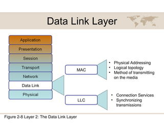
2) Each layer has a specific role like physical addressing (data link), logical addressing (network), and ensuring reliable data transmission (transport).
3) The TCP/IP model is similar to OSI but combines some layers. It uses IP addresses, TCP/UDP, and port numbers to route packets between applications running on devices.
4) Common network devices operate at different layers, with cables and wireless access points at layer 1