
Recommended
Recommended
More Related Content
What's hot
What's hot (20)
Similar to 7SR12 Directional Over Current Relay
Similar to 7SR12 Directional Over Current Relay (20)
More from ashwini reliserv
More from ashwini reliserv (20)
Recently uploaded
Recently uploaded (20)
7SR12 Directional Over Current Relay
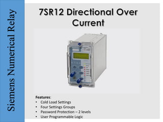
- 1. SiemensNumericalRelay Features: • Cold Load Settings • Four Settings Groups • Password Protection – 2 levels • User Programmable Logic
- 2. Description • The 7SR11 & 7SR12 are overcurrent protection relays developed to enhance the Argus family of products by providing a familiar product using the latest generation of hardware technology. • The 7SR11provides overcurrent and earth fault protection, the 7SR12 comes with additional voltage inputs providing directional protection. Both relays are available in single and four pole variants. • Housed in a 4U high, size E4 or E6 (Optional IEC61850 model) cases, these relays provide protection, monitoring, instrumentation and metering with integrated input and output logic, data logging & fault reports. Communication access to the relay functionality is via a front USB port for local PC connection, a rear electrical RS485 port for remote connection & optional IEC61850 communication through two rear Ethernet ports (Electrical or Optical).
- 3. Monitoring Functions • Primary/Secondary Current Phases and Earth Direction • Primary/Secondary Line and Phase Voltages • Apparent Power and Power Factor • Real and Reactive Power W Hr & VAr Hr Forward and Reverse • Historical Demand Record • Positive Phase Sequence (PPS) Voltage & Current • Negative Phase Sequence (NPS) Voltage & Current User Interface • 20 Character x 4 Line Backlit LCD • Menu Navigation Keys • 9 User Programmable Tri-colour LEDs • User Language Configuration
- 6. Function Overview • 37 Undercurrent • 46BC Broken Conductor / Load Unbalance • 46NPS Negative Phase Sequence Overcurrent • 49 Thermal Overload • 50 Instantaneous Overcurrent • 50G/N/SEF Instantaneous Earth Fault • 50AFD Arc Flash Detection (6 zones) • 50BF Circuit Breaker Fail • 51 Time Delayed Overcurrent • 51G/N/SEF Time Delayed Measured/Derived/Sensitive EF • 64H High Impedance REF • 27/59 Under/Over Voltage • 47 Negative Phase Sequence Voltage • 51V Voltage Controlled Overcurrent • 59N Neutral Voltage Displacement • 67/50 Directional Instantaneous Overcurrent • 67/50G/N Directional Instantaneous Earth Fault
- 7. Description of Functionality 27/59 Under/Over Voltage Each element has settings for pickup level, drop-off level and Definite Time Lag (DTL) delays. Operates if voltage exceeds setting for duration of delay 32S Sensitive Power This is provided in 4 pole SEF relays and provides elements operated by single phase measured current in the ISEF input. 37 Undercurrent Each element has settings for pickup level and Definite Time Lag (DTL) delays. 46BC Phase Unbalance/Broken Conductor Element has settings for pickup level and DTL delay. With the circuit breaker closed, if the NPS:PPS current ratio is above setting this could be due to a broken conductor. 46NPS Negative Phase Sequence Overcurrent Each element has user settings for pickup level and IDMTL or DTL delay, operates if NPS current exceeds setting and delay. 47 Negative Phase Sequence Voltage Each element has settings for pickup level and Definite Time Lag (DTL) delays. Operates if NPS voltage exceeds setting for duration of delay.
- 8. Description of Functionality 49 Thermal Overload The thermal algorithm calculates the thermal states from the measured currents and can be applied to lines, cables and transformers. Alarm outputs are given for thermal overload and thermal capacity. 50BF Circuit Breaker Fail The circuit breaker fail function may be triggered from an internal trip signal or from a binary input. 51c Cold Load Pickup If a circuit breaker is closed onto a ‘cold’ load, i.e. one that has not been powered for a prolonged period, this can impose a higher than normal load-current demand on the system which could exceed normal settings. 50/51 Phase Fault 50 INST/DTL and 51 IDMTL/DTL elements provide overcurrent protection, each with independent settings for pickup current, time-multiplier (51) and time-delays. 50G/51G/50N/51N Earth Fault/Sensitive Earth Fault Two earth fault measurement modes are available. One mode directly measures the earth current from an independent CT, or the residual connection of the 3 line CTs.
- 9. Description of Functionality 51V Voltage Controlled Overcurrent Each phase shaped overcurrent element can be independently controlled by the level of measured input voltage 50AFD Arc Flash Detector The 7SR1 relays can be used with the 7XG31 ReyArc range of Arc Flash Detection devices. 55 Power Factor Each element has settings for Under or Over Power Factor pickup level, Definite Time Lag (DTL) delay and Lead/Lag Direction. 59N Neutral Overvoltage Neutral overvoltage can be used to detect earth faults in high impedance earthed or isolated systems. 60CTS CT Supervision The relay has two methods of CT supervision. 67/67N Directional Control Phase, earth and sensitive earth fault elements can be directionalised.
- 10. Serial Communications • The relay offers a USB serial port as standard on the front of all units. All of the relays functions can be set on a PC using Reydisp Evolution via the USB port. The connection is made with a USB cable and operates with a ‘plug and play’ connection, so no pre-setting of the relay is required. • The front port can be switched off or set to use either the DNP3.0, MODBUS-RTU, IEC60870-5-103 and ASCII protocols for testing purposes. • A rear RS485 electrical connection is available on all units for system interface connections. An internal terminating resistor is provided, which can be connected into the circuit by adding a wire loop between the relevant terminals
- 11. Control Mode The relay has a control menu with access to commonly used command operations (except 7SR1102-1*A12-*AA0 models). Access to the control commands is restricted by a 4 character control function password. Each command requires a select then execute operation, if the execute operation is not performed within a time window the command is aborted. The following control functions are available: • CB Operation • Auto Reclose In/Out • Auto Reclose Trip & Reclose • Auto Reclose Trip & Lockout • SEF In/Out • Inst Prot In/Out • Hot Line Working In/Out
- 12. Reydisp Evolution • Reydisp Evolution is a Windows based software tool, providing the means for the user to apply settings, interrogate settings and retrieve events and disturbance waveforms from the device and is common to the entire range of Reyrolle protection relays.
- 13. Construction • The relay is housed in a 4U high, size E4 or E6 (Optional IEC61850 model) case with a removable clear fascia cover. The fascia cover can be ordered with or without two push buttons to allow the user to view the settings and instruments without removing the cover. • Two handles are provided to allow the relay to be withdrawn from its case, contacts in the case ensure that the CT circuits and normally closed contacts remain short circuited when the relay is withdrawn. • The rear terminal blocks comprise M4 female terminals for ring crimp wire connections, to provide a secure and reliable termination.
- 14. Data Communication Interface and Tests Communication Port Front USB Type B Rear RS485 2 wire electrical IEC61850 optional ports: 2x Electrical RJ45 Ethernet 2x LC Fibre Optic Ethernet Protocols IEC60870-5-103 MODBUS RTU (Serial) DNP3.0 O (Serial) IEC61850 - optional Fibre Optic Ethernet Data Communication Interface (IEC 61850 Option) Type Level Variation Vibration response 0.5 gn ≤ 5 % Vibration response 1.0 gn ≤ 5 % Vibration (Sinusoidal) Shock and Bump Type Level Variation Shock response 5 gn, 11 ms ≤ 5 % Bump test 10 gn, 16 ms ≤ 5 % Shock withstand 15 gn, 11 ms ≤ 5 %
- 16. Mob No: Mr. Piyush Rathi- +91-9819614841 Website: www.reliservsolution.com Email-ID: piyush@reliserv.in sales1@reliserv.in Address: Office No: 9, Space Heights, Plot No. 53/54 , Sector 34, Kamothe,Navi Mumbai- 410209 Contact us