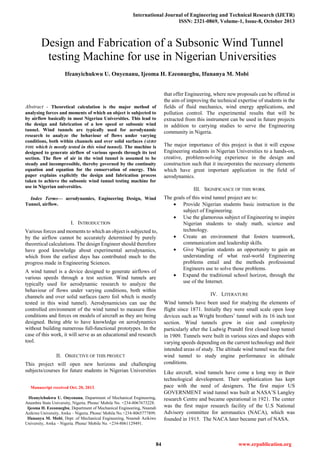
Ijetr011847
•
0 likes•58 views

ER Publication, IJETR, IJMCTR, Journals, International Journals, High Impact Journals, Monthly Journal, Good quality Journals, Research, Research Papers, Research Article, Free Journals, Open access Journals, erpublication.org, Engineering Journal, Science Journals,

Recommended
More Related Content
What's hot
What's hot (20)
Viewers also liked
Similar to Ijetr011847
Similar to Ijetr011847 (20)
More from ER Publication.org
Recently uploaded
Recently uploaded (20)
Ijetr011847
- 1. International Journal of Engineering and Technical Research (IJETR) ISSN: 2321-0869, Volume-1, Issue-8, October 2013 84 www.erpublication.org Abstract - Theoretical calculation is the major method of analysing forces and moments of which an object is subjected to by airflow basically in most Nigerian Universities. This lead to the design and fabrication of a low speed or subsonic wind tunnel. Wind tunnels are typically used for aerodynamic research to analyze the behaviour of flows under varying conditions, both within channels and over solid surfaces (AERO FOIL which is mostly tested in this wind tunnel). The machine is designed to generate airflow of various speeds through its test section. The flow of air in the wind tunnel is assumed to be steady and incompressible, thereby governed by the continuity equation and equation for the conservation of energy. This paper explains explicitly the design and fabrication process taken to achieve the subsonic wind tunnel testing machine for use in Nigerian universities. Index Terms— aerodynamics, Engineering Design, Wind Tunnel, airflow. I. INTRODUCTION Various forces and moments to which an object is subjected to, by the airflow cannot be accurately determined by purely theoretical calculations. The design Engineer should therefore have good knowledge about experimental aerodynamics, which from the earliest days has contributed much to the progress made in Engineering Sciences. A wind tunnel is a device designed to generate airflows of various speeds through a test section. Wind tunnels are typically used for aerodynamic research to analyze the behaviour of flows under varying conditions, both within channels and over solid surfaces (aero foil which is mostly tested in this wind tunnel). Aerodynamicists can use the controlled environment of the wind tunnel to measure flow conditions and forces on models of aircraft as they are being designed. Being able to have knowledge on aerodynamics without building numerous full-functional prototypes. In the case of this work, it will serve as an educational and research tool. II. OBJECTIVE OF THIS PROJECT This project will open new horizons and challenging subjects/courses for future students in Nigerian Universities Manuscript received Oct. 20, 2013. Ifeanyichukwu U. Onyenanu, Department of Mechanical Engineering, Anambra State University, Nigeria. Phone/ Mobile No. +234-8067673228. Ijeoma H. Ezeonuegbu, Department of Mechanical Engineering, Nnamdi Azikiwe University, Awka – Nigeria. Phone/ Mobile No.+234-8065777899. Ifunanya M. Mobi, Dept. of Mechanical Engineering, Nnamdi Azikiwe University, Awka – Nigeria. Phone/ Mobile No. +234-8061129491. that offer Engineering, where new proposals can be offered in the aim of improving the technical expertise of students in the fields of fluid mechanics, wind energy applications, and pollution control. The experimental results that will be extracted from this instrument can be used in future projects in addition to carrying studies to serve the Engineering community in Nigeria. The major importance of this project is that it will expose Engineering students in Nigerian Universities to a hands-on, creative, problem-solving experience in the design and construction such that it incorporates the necessary elements which have great important application in the field of aerodynamics. III. SIGNIFICANCE OF THIS WORK The goals of this wind tunnel project are to: Provide Nigerian students basic instruction in the subject of Engineering. Use the glamorous subject of Engineering to inspire Nigerian students to study math, science and technology. Create an environment that fosters teamwork, communication and leadership skills. Give Nigerian students an opportunity to gain an understanding of what real-world Engineering problems entail and the methods professional Engineers use to solve those problems. Expand the traditional school horizon, through the use of the Internet. IV. LITERATURE Wind tunnels have been used for studying the elements of flight since 1871. Initially they were small scale open loop devices such as Wright brothers’ tunnel with its 16 inch test section. Wind tunnels grew in size and complexity particularly after the Ludwig Prandtl first closed loop tunnel in 1909. Tunnels were built in various sizes and shapes with varying speeds depending on the current technology and their intended areas of study. The altitude wind tunnel was the first wind tunnel to study engine performance in altitude conditions. Like aircraft, wind tunnels have come a long way in their technological development. Their sophistication has kept pace with the need of designers. The first major US GOVERNMENT wind tunnel was built at NASA’S Langley research Centre and became operational in 1921. The center was the first major research facility of the U.S National Advisory committee for aeronautics (NACA), which was founded in 1915. The NACA later became part of NASA. Ifeanyichukwu U. Onyenanu, Ijeoma H. Ezeonuegbu, Ifunanya M. Mobi Design and Fabrication of a Subsonic Wind Tunnel testing Machine for use in Nigerian Universities
- 2. Design and Fabrication of a Subsonic Wind Tunnel testing machine for use in Nigerian Universities 85 www.erpublication.org The first major wind tunnel was built at NASA’S research center in 1920.late in the last century, however , the first wind tunnels were little more than boxes or pipes. A fan or other device propelled air over a model of an aircraft of wing suspended in the pipe or box. Observation instruments were crude. The researchers had to gather many of the test results with their own eyes. The Wright brothers designed and used such primitive tunnels to develop the wing configurations and control surfaces with which they achieved the first powered human flight early in the century. Today’s aircraft are larger, cruise faster and higher, carry more passengers and cargo, and use less fuel per mile than most of their predecessors. Aircraft now being developed are expected to show significant improvements in all of these performance characteristics. Various methods and devices are employed for performing the measurement of the forces, moments, torques and pressures to which the models, attached to special balances or rigidly supported are subjected to in the wind tunnel. The airflow pattern can be made visible by a number of methods. There are several categories of wind tunnels; low speed tunnels, high speed tunnels (subsonic) and transonic tunnels. Up to the late 1920’s, wind tunnels were all of the low speed type, producing maximum air speeds of about 120mph. high speed subsonic tunnels and supersonic tunnels were developed in the following decade. For a time, there was a gap between the subsonic and the supersonic speed ranges, which was bridged by the transonic wind tunnel, a post war development, enabling tests to be made right through the transonic range approximately between Mach 0.8 and Mach 1.2. The hypersonic wind tunnel, the most recent development is used for studying the conditions associated with the launching and flight of rocket propelled missiles and earth satellites. In the subsonic wind tunnel, the test section is located at the narrowest part of the duct, where the highest speeds below the speed of sound is produced. In the supersonic wind tunnel, the test section is preceded by a construction, a so- called convergent divergent nozzle, in which the very high speeds are attained. Each different supersonic speed requires the use of a differently shaped nozzle; in some tunnels, the nozzle has a flexible wall so that it can be varied by shape by the hydraulic adjusting equipment instead of having to be exchanged for another, beyond the test section is a second constriction, in which the ultrasonic speed diminishes to subsonic values. The wind is produced by a multi stage axial flow compressor or by the high speed jet from a set of gas turbines. The friction of the wind against the tunnel walls generates heat, which is removed by a cooler incorporated into the circuit, so as to maintain a continuous flow of air at supersonic speeds is very high. For very high speeds this becomes a very uneconomical method of operation and to overcome this problem intermittently operated wind tunnels have been developed. In recent years it has become common practice to install a wire net behind the honeycomb, in order to dampen turbulence and to increase the uniformity of the velocity distribution. V. WORKING PRINCIPLE OF THE WIND TUNNEL Air is blown or sucked through a duct equipped with a viewing port and instrumentation where models or geometrical shapes are mounted for study. Typically the air is moved through the tunnel using a series of fans. For very large wind tunnels several meters in diameter, a single large fan is not practical, and so instead an array of multiple fans is used in parallel to provide sufficient are flow. Due to the sheer volume and speed of air movement required, the fans may be powered by stationary turbo fan engines rather than electric motors The airflow created by the fans that is entering the tunnel is itself highly turbulent due to the fan blade motion (when the fan is blowing air into the test section - when it is sucking air out of the test section downstream, the fan blade turbulence is not a factor), and so is not directly useful for accurate measurements. The air moving through the tunnel needs to be relatively turbulence free and laminar. To correct this problem, closely spaced vertical and horizontal air vanes are used to smooth out the turbulent air flow before reaching the subject of the testing Due to the effects of viscosity the cross-section of a wind tunnel is typically circular rather than square because there will be greater flow constriction in the corners of a square tunnel that can make the flow turbulent. A circular tunnel provides a smoother flow. The inside facing of the tunnel is typically as smooth as possible, to reduce surface drag and turbulence that could impact the accuracy of the testing. Even smooth walls induce some drag into the airflow, and so the object being tested is usually kept near the center of the tunnel, with an empty buffer zone between the object and the tunnel walls. There are correction factors to relate wind tunnel test results to open air result. Lighting is usually recessed into the circular walls of the tunnel and shines in through windows. If the light were mounted on the inside surface of the tunnel in a conventional manner, the light bulb would generate turbulence as the air blows around it. Similarly, observation is usually done through transparent portholes into the tunnel. Rather than simply being flat discs, these lighting and observation windows may be curved to match the cross section of the tunnel and further reduce turbulence around the window Various techniques are used to study the actual airflow around the geometry and compare it with theoretical results which must also take into account the Reynolds number and Mach number for the regime of operations. Governing Equations The flow of air in a subsonic wind tunnel is assumed to be steady and incompressible. The following two equations govern this type of flow:
- 3. International Journal of Engineering and Technical Research (IJETR) ISSN: 2321-0869, Volume-1, Issue-8, October 2013 86 www.erpublication.org The continuity equation ………………………………….. (1) The conservation of energy …… (2) VI. PARTS DESIGN AND MATERIAL SELECTION The contraction section – a large contraction ratio helps reduce free stream turbulence and promotes cross sectional uniform flow in the test section, the design geometric contraction ratio of this tunnel is 7.5: 1, a value based on building size restriction and test section size requirements. This was designed in respect to previous methods of nozzle contraction contours, which was an analytical technique developed to yield maximum pressure recovery or minimum flow losses while tunneling the air through the 7.5 contraction. The settling chamber – this contains the honeycombs and screens. Screens in chamber were spaced at 0.2 chamber diameters apart so that flow disturbed by the first screen can settle before it encounters the second screen. Honey combs should be 6 – 8 cell diameters thick and cell size should be on the order of about 150 cells per settling chamber diameter (Nathan Tatman). A screen is characterized by its open area ratio which is defined in the equation below where d is the wire diameter and L is the length of the screen. At least one screen in the settling chamber should have the open area ratio of B as screens with lower ratios are known to produce non uniformities in flow. Test section – the test sections shape and size are largely determined by testing requirements. The test section should be long enough that flow disturbances resulting from a contraction or screens are sufficiently damped before reaching the test object. However care should be taken not to make this section too long as this will lead to detrimental boundary layer growth which can separate when it enters the exit diffuser and create a power loss. The diffuser – the cross sectional shape of the diffuser varies from the test section shape (Square) to an octagonal shape. The diffusion angle is 5 , a value well below the 7 angle to be considered to be the stall angle. The 5 diffusion angle in the vertical plane permits enough latitude (vertical distance measured in degrees north or south) for changing the test section cross section to a square with the resulting vertical diffusion angle not exceeding 70 . These design considerations gave rise to the tunnels geometry and dimension which is stated below: Parts Dimensions Settling chamber 400mmx400mmx400mm Number of honey comb per setting chamber surface area. 7725 Honey comb diameter 5mm Contraction section Ao = 300,000mm2 A0 = 40,000mm2 Test section 550mmx200mmx200mm Diffuser Ao = 40,000mm2 A0 = 221,400mm2 L = 1000mm VII. DESIGN CALCULATIONS a. Wind Tunnel Power Requirement The power required to maintain steady flow through the wind tunnel is equal to the total losses accruing in the flow through the tunnel. These losses are due to kinetic energy being dissipated by vorticity (a measure of the rate of rotational spin in a fluid) and turbulence (haphazard motion that occurs in a moving fluid). The loss in kinetic energy, which appears as a decrease in pressure must be compensated by a pressure rise, usually provided by a fan. Thus, if the power input of the fan is P (i.e. motor shaft output) and the fan has an efficiency ɳ. the equation balancing the energy input of the stream to the energy losses in the tunnel is: …………………….………. (3) The tunnel can be divided into sectors with the energy loss of each section written as a drop in pressure △P or a pressure drop coefficient: …………………………………..……….. (4) is test section dynamic pressure given by; ………………………..…….… (5) The flow energy through the test section is: ……………………..…..…. (6) The energy loss in each tunnel section is: ………………..……… (7) Substituting; ………......…… (8) ……………………..…… (9) From the equation of continuity, ……………..….… (10) For subsonic flow with M < 0.4, (Within 1%) and equation 3 becomes ………………………… (11) The required power for a given test section size and a flow
- 4. Design and Fabrication of a Subsonic Wind Tunnel testing machine for use in Nigerian Universities 87 www.erpublication.org condition depends on the sum of pressure drop coefficient (k□) in the various tunnel sections. A reduction in these coefficients improves the tunnel efficiency. Tunnel performance is related by the energy ratio equation below: ……………………. (12) And is a measure of the tunnels’ efficiency. b. Pressure Losses Determination The loss coefficient for each section is determined by finding the friction losses in each section. The friction coefficient is generally tabulated as a function of Reynolds number. In case of a non-circular cross-section which is what we are dealing with, hydraulic diameter can be used, this is defined as: Where A is cross-sectional area and C is wetted perimeter. Using hydraulic diameter gives good results for circular pipes in turbulent regimes (ReDh > 2000) Wall friction and expression losses occur in divergent sections. The combined losses for a constant divergent angle are: ……… (13) Where D1 = small diameter, D2 = large diameter, D0 = test section diameter. Differentiating the equation leads to an optimum expansion when i. Contraction Section Losses The losses in the contraction section are due skin friction can be calculated from the formula below. Assuming a constant taper for the contraction and integrating gives ………………… (14) Where is the length, the test section diameter and the in-let cone diameter. Note: For a non-circular section, one can replace the diameters with the hydraulic diameter formula. ii. Diffuser Losses The diffuser losses are due to both skin friction and expansion in order to avoid separation in the diffuser, the maximum divergence angle should be approximately 50 total angle. This value agrees with the optimum expansion angle for a friction factor The addition of losses results in a total diffuser loss co-efficient equal to ……… (15) Where De is diffuser exit diameter. iii. Test Section Losses The test section loss coefficient for a constant area section using equation (14) and a mean value of the friction factor reduces to ………….…………………….……. (16) iv. Settling Chamber Losses The losses in the settling chamber are primarily due to screens used for turbulence reduction. The recommended screen mesh should give a pressure loss equal to twice the local dynamic pressure. The contraction ratio affects the total wind tunnel pressure loss due to the screen. For a given choice of screen pressure loss coefficient k, the tunnel pressure loss coefficient is: ……………….……………..…….. (17) Where Since the losses are inversely proportional to the square of the contraction ratio it is desirable to have a large contraction ratio for power economy. Calculated Results for pressure Losses in the wind tunnel S/N Types of Pressure Losses Values 1. Contraction Section Losses 2.6733 x 10⁻³ 2. Diffuser Losses 0.04837 3. Test Section Losses 0.02509 4. Settling Chamber Losses 0.15625 VIII. FABRICATION OF THE WIND TUNNEL COMPONENTS Test section: The test section was designed to house the aero foil; which is the test model for the tunnel; it has a dimension of 200mm which is compatible to the outlet and inlet of the nozzle and diffuser respectively.
- 5. International Journal of Engineering and Technical Research (IJETR) ISSN: 2321-0869, Volume-1, Issue-8, October 2013 88 www.erpublication.org Transparent plexi glass was used in its construction to provide viewing of the model. A square cross section was chosen to optimize the available space inside the balance while at the same time providing plane surface on the walls to eliminate optical distortion of the model. It has flanges attached to both ends where it is connected to both the contraction section and the diffuser. A frame was constructed using a one inch bar to hold these flanges and house the plexi glass. Stilling section: the stilling section is made of sheet metal, cut to a dimension of 400mm and bent into a square tube. This sheet is folded into four sides and joined with weld at one end. This stilling section contained the screen and the honey comb. Honey comb: the unavailability of honey combs in the market restricted us and so we improvised by using plastic straws for its construction. The straws were cut to a 50mm length each and were housed in a metal sheet bent to match the dimensions of the stilling chamber. The straws were glued together with a tiny film of glue. The honey comb frame had a tight fit to the walls of the stilling chamber and had no need of fixtures. Screen: a pair of screens was placed downstream of the honey comb to further even out the flow. The screen was made of resin in form of mosquito nets which has equivalent porosity and features to the previously designed screen parameters. These screens were cut to size and then tacked to a 4mm smooth cylindrical rod which is bent to a square that matched the settling chamber dimensions. These screens were secured to the settling chamber dimensions. These screens were secured to the settling chamber walls in the same manner as the honey comb. Contraction section: the contraction section is made of sheet metal. It has a square cross section of 10: 1 contraction ratio. The four sides were cut out from sheet metal and joined with weld to form a pyramid with a slit top (frustum shape). The inlet dimension, were cut to match the stilling section while the outlet end of the inlet of the test chamber (200mm . The outlet section has a flange that was connected to the inlet test section flange. The inlet area was welded smoothly together with the stilling chamber. The nozzle (contraction section) where fitted to the test section with the aid of bolts and nuts, soft 2mm smooth paper gaskets were used in between the two flanges to prevent air leakage thereby sealing the joint. Diffuser: the diffuser was also made of sheet metal and is octagonal in exit cross section and square inlet cross section. A constant divergence angle of 5 between opposing walls was used. The diffuser attaches to the downstream test section flanges. The diffuser exit matches the fan inlet with 483mm inscribed radius. The diffuser inlet section is attached to the test section with a gasket held tight in between the flanges. The diffuser has a length of 1000mm with the cut out rectangles and keenly joined outwardly by precision welding to form the diffuser shape shown below. Power plant: an axial fan driven by a 1Hp alternating current motor provides the power to the tunnel. The fan is directly fixed to the motor shaft. Power Requirement Estimate The power requirement for the tunnel was calculated using the methods described in chapter 3. The velocities in the tunnel varied because the motor has a three level speed control. This also varied the pressure and mass flow rate in the tunnel. Fan Selection: The fan chosen is an axial fan, made by HUDSON Corporation. The fan diameter and the operating characteristics of the fan are listed on the pack. Its characteristics match the tunnel air flow requirements. It has eight axial rotor blades, inclined at an angle of 25 with maximum air velocity propulsion of 200m/s and an efficiency of 67%. Motor Selection: A single phase 1 H.P alternating current motor was selected to drive the axial fan. The motor is made by General Electric Company. The maximum speed for this motor is 1500rpm. IX. BILL OF MATERIALS AND QUANTITY Fabrication Materials Qty. 1 HP electric motor 1 1.5mm thick mild steel sheet 2 2’ angle bar (mild steel) 2 1’ angle bar (mild steel) 1 1.5’angle bar (mild steel) 1 Axial flow fan 1 5mm plexi glass sheet 1 Gasket(2mm thickness) 2 Nets (fibre type) 2 Plastic Straws 100 10mm bolt & nut 30 13mm bolt & nut 20 17mm bolt & nut 10 3mm connecting wire 1 Rubber stands 8 Paint (oil) 1 Instrumentation model 1 Protractor 1 Digital Anemometer 1 Varying speed control switch 1 Switch 1
- 6. Design and Fabrication of a Subsonic Wind Tunnel testing machine for use in Nigerian Universities 89 www.erpublication.org Plug (3 pin) 1 Copper wire 1 Electrode (1 Pack) 1 4x100” plank 1 X. PICTORIAL REPRESENTATION OF THE WIND TUNNEL Fig 1: Fully fabricated subsonic wind tunnel Fig 2: Showing the fan and the motor Fig 3: Showing the Stilling section Fig 4: Showing the test section Fig 5: Showing the Contraction section Fig 6: Showing the Honey comb section XI. TESTING AND RESULTS Following the assembly of the various tunnel components, the tunnel was tested to obtain the tunnel calibrations and evaluation of its performance. Preliminary measurements indicated that a static pressure is approximating fan speed. Pressure Measurement in Test Section In the test section, two anemometers were attached through tubing to a transmitter. Data output pole was used to measure voltage drop across a resistor. The variable resistor used was set to one kilo ohm, but the formula used to convert the voltage reading to a current usually require resistance values between 895 and 925 to obtain the correct calibration.
- 7. International Journal of Engineering and Technical Research (IJETR) ISSN: 2321-0869, Volume-1, Issue-8, October 2013 90 www.erpublication.org The current reading is then converted to a pressure value using the conversion 4mA is equal to 0 inches of water column, and maximum output of 20mA is equal to 3 inches of water column. (1 inch of water column is equal to 249N/m2 . All other values can be obtained from extrapolating of this linear relation. The pressure reading is the value of the dynamic pressure due to the fluids movement which is related to fluid velocity according to the formula below; P From this relation, air velocity can be obtained and Reynolds number will be computed using the velocity values. Using known constants and the expression for the Reynolds number quoted, Re At any velocity in the test section; Re Re Test Section Speed Cutting The anemometer readings were used to determine the speed of the motor. The control box consists of variable output transformer and a rotating knob. This process was more of a trial and error process as the coils were wound round the voltage out of the transformer at some turns was used to test the motor and velocity readings were obtained. The control box was calibrated at three points where the knob can regulate the motor speed at desired velocity in the test section. Unlike the speed control sought to be bought in the market which can provide continuous variation of fan speed from less than 2 rpm to 1500rpm, ours controlled at three different speeds XII. CONCLUSION This instrument will help to boast up the practical aspect of research and development in Nigeria especially amongst Universities in Nigeria as it will help them in the acquisition of basic knowledge in aerodynamics for Engineering student since the tunnel can be used to test structures, wind turbines, houses, cars, and virtually everything that moves and occupies space. RECOMMENDATION Institutions in Nigeria should really emphasize on the acquisition of basic knowledge in aerodynamics for Engineering student since the tunnel can be used to test structures, wind turbines, houses, cars, and virtually everything that moves and occupies space. REFERENCES [1] High speed flight. www.wikipedia.org. Wikipedia, the free encyclopedia. [2] J.F. Douglas, J.M. Gasiorek, J.A. Swaffield. Fliud Mechanics, third edition. Singapore: Longman Publishers. [3] Kelly Butler, David Concil. Design of a supersonic wind tunnel. Major qualifying project. Worcester Polytechnic Institute. March 2010. [4] Vernon O. Hoehne, The subsonic wind tunnel of Battelle Columbus Laboratories. June 1967. [5] The wind tunnel. www.wikipedia.org. Wikipedia, the free encyclopedia. [6] www.a2windtunnel.com, A2 wind tunnel information. [7] Yunus Cengel Michael A. Boles. Thermodynamics an Engineering approach. Fifth edition, New Delhi: McGraw Hill; 2006. Ifeanyichukwu Ugochukwu Onyenanu (AMIMechE, MIAEng.) had his BEng. In Mechanical Engineering from Anambra state university, Nigeria. He is currently on his master in same school. He specializes in Engineering Design. Some of his works included; Correlation of Automobile Bumper with the Geometry of the Bumper, Detection and Treatment of Human Cancer: Nanotechnology Application, a case study, He is a member of the Institution of Mechanical Engineers, London (IMechE), International association of Engineers (IAEng). He won the Engineering Global population competition, 2011 @ the House of Commons, London. He is the founder and leader of the Nuta_Bolts Team (The first team in Nigeria to represent in the Formula student Competition). Ijeoma Happiness Ezeonuegbu (BEng. Mechanical Engineering) is a Lecturer in the Department of Mechanical Engineering, Nnamdi Azikiwe University – Nigeria. Her Area of specialization is Thermal Engineering. She is a member of the Institution of Mechanical Engineers, London (IMechE). Ifunanya Mariagoretti Mobi holds HND in Mechanical Engineering from Federal Polytechnic, NEKEDE – Nigeria. She is currently on her Postgraduates in Department of Mechanical Engineering, Nnamdi Azikiwe University – Nigeria. She specializes in Engineering Design. She is a member of the Institution of Mechanical Engineers, London (IMechE).