
Recommended
More Related Content
What's hot
What's hot (20)
Similar to Lecture 1
Similar to Lecture 1 (20)
More from aneesurrehman54
Recently uploaded
Recently uploaded (20)
Lecture 1
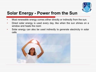
- 1. Solar Energy - Power from the Sun • Most renewable energy comes either directly or indirectly from the sun. • Direct solar energy is used every day, like when the sun shines on a window and heats the room • Solar energy can also be used indirectly to generate electricity in solar cells
- 2. SOLAR ELECTRIC Electricity can be generated in two ways i. Solar Thermal Electric • Solar heat is used to drive heat engines, which can be coupled to a generator to produce electricity. ii. Solar Photo Electric • Sun rays can be converted directly to electricity using Semi-Conductors Semi Conducting photovoltaic cells i.e. Solar Cell
- 4. Active solar heating • Active solar heating is the gathering of solar energy by collectors that are used to heat water or heat a building • Solar collectors, usually mounted on a roof, capture the sun’s energy • A liquid is heated by the sun as it flows through solar collectors • The hot liquid is then pumped through heat exchangers, which heats water for the building.
- 7. Introduction • For applications such as air conditioning, central power generation, and numerous industrial heat requirements, flat plate collectors generally cannot provide carrier fluids at temperatures sufficiently elevated to be effective. • Alternatively, more complex and expensive concentrating collectors can be used. • These are devices that optically reflect and focus incident solar energy onto a small receiving area. • As a result of this concentration, the intensity of the solar energy is magnified, and the temperatures that can be achieved at the receiver (called the "target") can approach several hundred or even several thousand degrees Celsius. • The concentrators must move to track the sun if they are to perform effectively
- 8. Concentrating collectors • Concentrating, or focusing, collectors intercept direct radiation over a large area and focus it onto a small absorber area. • These collectors can provide high temperatures more efficiently than flat-plate collectors, since the absorption surface area is much smaller. • However, diffused sky radiation cannot be focused onto the absorber. • Most concentrating collectors require mechanical equipment that constantly orients the collectors toward the sun and keeps the absorber at the point of focus. • Therefore; there are many types of concentrating collectors
- 9. Types of concentrating collectors Parabolic trough system Parabolic dish Power tower Stationary concentrating collectors There are four basic types of concentrating collectors:
- 10. Parabolic trough system Parabolic troughs are devices that are shaped like the letter “u”. The troughs concentrate sunlight onto a receiver tube that is positioned along the focal line of the trough. Figure 3.1.2 Parabolic trough system Figure 3.1.1 Crossection of parabolic trough
- 11. Parabolic troughs often use single-axis or dual-axis tracking Figure 3.1.3 One Axis Tracking Parabolic Trough with Axis Oriented E-W Figure 3.1.4 Two Axis Tracking Concentrator
- 12. Temperatures at the receiver can reach 400 °C and produce steam for generating electricity. Multi-megawatt power plants have been built using parabolic troughs combined with gas turbines (California). Figure 3.1.5 Parabolic trough combined with gas turbines
- 13. Parabolic dish systems A parabolic dish collector is similar in appearance to a large satellite dish, but has mirror-like reflectors and an absorber at the focal point. It uses a dual axis sun tracker Figure 3.2.1 Crossection of parabolic dish
- 14. A parabolic dish system uses a computer to track the sun and concentrate the sun's rays onto a receiver located at the focal point in front of the dish. Parabolic dish systems can reach 1000 °C at the receiver.
- 15. Power tower system A heliostat uses a field of dual axis sun trackers that direct solar energy to a large absorber located on a tower. To date the only application for the heliostat collector is power generation in a system called the power tower (solar tower) Figure 3.3.2 Heliostats Figure 3.3.1 Power tower system
- 16. A heliostat (from helios, the Greek word for sun, and stat, as in stationary) is a device incorporating a mirror which moves so as to keep reflecting sunlight toward a predetermined target or receiver, despite the sun's apparent motions in the sky. The target is stationary relative to the heliostat, so the light is reflected in a fixed direction. Most modern heliostats are controlled by computers. The computer is given the heliostat's position on the earth (latitude and longitude) and the time and date, and uses them to calculate the direction of the sun as seen from the mirror.
- 17. A power tower has a field of large mirrors that follow the sun's path across the sky. The mirrors concentrate sunlight onto a receiver on top of a high tower. A computer keeps the mirrors aligned so the reflected rays of the sun are always aimed at the receiver, where temperatures well above 1000°C can be reached. High- pressure steam is generated to produce electricity. Figure 3.3.3 Power tower system with heliostats
- 18. Solar Photo-voltaic (PV) Systems
- 19. How electricity is generated through Solar Energy? Solar photo voltaic (SPV). Can be used to generate electricity form the sun. Silicon solar cells play an important role in generation of electricity.
- 20. Photovoltaic cells Sunlight falls on a semiconductor, causing it to release electrons. The electrons flow through a circuit that is complete when another semiconductor in the solar cell absorbs electrons and passes them on to the first semiconductor.
- 21. How solar cells Generate electricity
- 22. 22 Absorption of Light by Atoms Sources: http://members.aol.com/WSRNet/tut/absorbu.htm, http://csep10.phys.utk.edu/astr162/lect/light/absorption.html Single electron transition in an isolated atom • Absorption occurs only when the energy of the light equals the energy of transition of an electron Light
- 23. In dye-sensitized solar cells… Talk about highest occupied molecular orbital (HOMO) and lowest unoccupied molecular orbital (LUMO) 23 So What Does this Mean for Solar Cells? Source: Original Images • In single-crystal silicon solar cells… – Talk about “conduction band” (excited states) and “valence band” (ground states)
- 24. 24 How a Silicon-Based Solar Cell Works Source: http://nanosense.org/activities/cleanenergy/solarcellanimation.html • A positive “hole” is left in the electron’s place • This separation of electrons and holes creates a voltage and a current • Light with energy greater than the band gap energy of Si is absorbed • Energy is given to an electron in the crystal lattice • The energy excites the electron; it is free to move Click image to launch animation (requires web access)
- 25. Solar Cell Schematic . . Protective Cover-Glass Electrical Contact Antireflective Layer N P-N Junction P Electrical Contact Load current P
- 26. Sunlight is made of photons, small particles of energy. These photons are absorbed by and pass through the material of a solar cell or solar PV panel. The photons 'agitate' the electrons found in the material of the photovoltaic cell. As they begin to move (or are dislodged), these are 'routed' into a current. This, technically, is electricity - the movement of electrons along a path. The Process
- 27. Working Principle of Solar Cell 27 Source: https://www.youtube.com/watch?v=j1jF3in2JUE
- 28. From Cells to Modules The open circuit voltage of a single solar solar cell is approx 0.5V. Much higher voltage voltage is required for practical application. Solar cells are connected in series to increase its open circuit voltage.
- 29. Groups of solar cells can be packaged into modules, panels and arrays to provide useful output voltages and currents to provide a specific power output.
- 30. 30
- 31. • Mono-crystalline solar panels, silicon is formed into bars and cut into wafers. • These types of panels are called “mono-crystalline” to indicate that the silicon used is single- crystal silicon. • These cell is composed of a single crystal, the electrons that generate a flow of electricity have more room to move. • As a result, monocrystalline
- 32. Polycrystalline solar panels are also made from silicon. Polycrystalline solar panels are also referred to as “multi- crystalline,” or many- crystal silicon. There are many crystals in each cell, there is to less freedom for the electrons to move. As a result, polycrystalline solar panels have lower efficiency ratings than monocrystalline
- 33. pervoskite solar cell Advantages High power to weight ratio High power to cost ratio Minimum materials per Watt High absorption Capabilities Flexible and easy to install Simple manufacturing Convenience of shape and size Fig: Flexible Substrate
- 34. Solar Cell Efficiencies 1st Generation 2nd Generation 3rd Generation Mono Poly a-Si CdTe DSSC PSC 22-25% 14- 18% 6- 7.7% 9- 12.5% 13-14% 25%
- 35. Solar cell In principle, a solar cell is a junction device obtained by placing two electronically dissimilar materials together with a thin barrier. Solar cell works on the principle of photo-electric effect i.e. the ejection of electrons from the metal surface in response to incident light. The basic steps of photovoltaic energy conversion Light absorption Charge separation Charge collection. 35
- 36. Plasmonic Effect Surface plasmon resonance (SPR) has the optical control ability to trap light in solar cells. The metal NP boost the light absorption capability of dye molecules Core-Shell Ag@TiO2 Nanostructure avoid the metal core from being degraded by dye molecules and electrolyte Fig. Surface Plasmon Resonance Fig. Core-Shell Nano particle Structure
- 37. Shell Thickness Effect Fig. Illustration of LSPR and UV-VIS Absorption Spectra of Cu@TiO2 NS with Shell Thicknesses of 3, 5, 7, and 10 nm (blue, green, pink and red respectively)
- 38. Electric Field Intensity Distribution Fig. EFI Distribution of Cu@TiO2 by FDTD Analysis at 520nm for Shell Thickness of (a) 3nm (b) 5nm (c) 7nm (d) 10nm
- 39. Results of Objectives-2 • The photo-anode based on Titanium Oxide, Graphene Oxide, and their bilayer composite were modeled using COMSOL Multiphysics Figure: Photo-anode based on (a) Graphene oxide, (b) Titanium oxide and (c) bilayer composite of Graphene oxide/Titanium oxide (GO/TiO2)
- 40. Absorption VS Wavelength • DSSC based on bilayer composite materials has broadband absorption (24.4%) as compared to that based on pure TiO2 and GO layers. • Bilayer structure that resulted in a larger surface area for dye loading. • As the coming light trapped for a long time so the photon interaction with the dye molecules is increased and produces many excited electrons that jump to the conduction band of GO/TiO . Fig. 3 UV-Visible absorption spectrum of oxides based photo-anode without silver nanoparticles
- 41. Selected Figures from Paper 4 Fig. 1. various geometries of aluminum nanoparticles embedded in SiO2 Fig. Schematic diagram of Composite bilayer structure of TiO2/SiO2 photoanode based on (a) spherical-shaped (b) nanorod/nanosphere (c) nanosphere/nanorod
- 42. Conclusion from the Characteristics. Power of the module has only single maxima. Peak Power of the module changes with the change in temperature. Need to track the peak power in order to maximize the utilizations of the solar module/array.
- 43. Photo-voltaic systems: Applications Using the sun to generate electricity
- 44. Solar Home Systems Space Water Pumping Telecom Main Application Areas – Off-grid
- 45. Residential Home Systems (2-8 kW) PV Power Plants ( > 100 kW) Commercial Building Systems (50 kW) Main Application Areas - Grid-connected