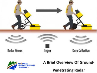
A Brief Overview of Ground-penetrating radar
•
0 likes•112 views

Ground Penetrating Radar, also known as GPR, is a tool that is used to find Underground Utilities, Underground Storage Tanks (USTs), and in some cases, Graves. The depth and accuracy are dependent on a number of variables, such as soil density, moisture content, and antenna frequency. We use a 350 MHz antenna, which has the potential to reach depths of up to 35 ft (in perfect situations).

Recommended
More Related Content
What's hot
What's hot (20)
Similar to A Brief Overview of Ground-penetrating radar
Similar to A Brief Overview of Ground-penetrating radar (20)
More from Advanced Infrastructure Mapping, LLC
More from Advanced Infrastructure Mapping, LLC (16)
Recently uploaded
Recently uploaded (20)
A Brief Overview of Ground-penetrating radar
- 1. A Brief Overview Of Ground- Penetrating Radar
- 3. Ground-penetrating radar (GPR) is a geophysical method that uses radar pulses to image the subsurface. This non-destructive method uses electromagnetic radiation in the microwave band (UHF/VHF frequencies) of the radio spectrum, and detects the reflected signals from subsurface structures.
- 4. GPR can have applications in a variety of media, including rock, soil, ice, fresh water, pavements and structures. In the right conditions, practitioners can use GPR to detect subsurface objects, changes in material properties, and voids and cracks.
- 5. GPR uses high-frequency (usually polarized) radio waves, usually in the range 10 MHz to 2.6 GHz. A GPR transmitter and antenna emits electromagnetic energy into the ground. When the energy encounters a buried object or a boundary between materials having different permittivities, it may be reflected or refracted or scattered back to the surface.
- 6. A receiving antenna can then record the variations in the return signal. The principles involved are similar to seismology, except GPR methods implement electromagnetic energy rather than acoustic energy, and energy may be reflected at boundaries where subsurface electrical properties change rather than subsurface mechanical properties as is the case with seismic energy.
- 7. The electrical conductivity of the ground, the transmitted center frequency, and the radiated power all may limit the effective depth range of GPR investigation. Increases in electrical conductivity attenuate the introduced electromagnetic wave, and thus the penetration depth decreases. Because of frequency-dependent attenuation mechanisms, higher frequencies do not penetrate as far as lower frequencies. However, higher frequencies may provide improved resolution.
- 8. Thus operating frequency is always a trade-off between resolution and penetration. Optimal depth of subsurface penetration is achieved in ice where the depth of penetration can achieve several thousand metres (to bedrock in Greenland) at low GPR frequencies.
- 9. Dry sandy soils or massive dry materials such as granite, limestone, and concrete tend to be resistive rather than conductive, and the depth of penetration could be up to 15 metres (49 ft). However, in moist or clay-laden soils and materials with high electrical conductivity, penetration may be as little as a few centimetres.
- 10. A GPR system is made up of three main components: • Control unit • Antenna • Power Supply
- 11. GPR Control Unit and Antenna
- 12. The control unit contains the electronics which trigger the pulse of radar energy that the antenna sends into the ground. It also has a built-in computer and hard disk/solid state memory to store data for examination after fieldwork.
- 13. Some systems, such as the GSSI SIR 30, are controlled by an attached Windows laptop computer with pre-loaded control software. This system allows data processing and interpretation without having to download radar files into another computer.
- 14. The antenna receives the electrical pulse produced by the control unit, amplifies it and transmits it into the ground or other medium at a particular frequency. Antenna frequency is one major factor in depth penetration. The higher the frequency of the antenna, the shallower into the ground it will penetrate.
- 15. A higher frequency antenna will also ‘see’ smaller targets. Antenna choice is one of the most important factors in survey design. The following table shows antenna frequency, approximate depth penetration and appropriate application.
- 16. GPR Method
- 17. GPR works by sending a tiny pulse of energy into a material and recording the strength and the time required for the return of any reflected signal. A series of pulses over a single area make up what is called a scan. Reflections are produced whenever the energy pulse enters into a material with different electrical conduction properties or dielectric permittivity from the material it left.
- 18. The strength, or amplitude, of the reflection is determined by the contrast in the dielectric constants and conductivities of the two materials. This means that a pulse which moves from dry sand (dielectric of 5) to wet sand (dielectric of 30) will produce a very strong reflection, while moving from dry sand (5) to limestone (7) will produce a relatively weak reflection.
- 19. While some of the GPR energy pulse is reflected back to the antenna, energy also keeps traveling through the material until it either dissipates (attenuates) or the GPR control unit has closed its time window. The rate of signal attenuation varies widely and is dependent on the properties of the material through which the pulse is passing.
- 20. Materials with a high dielectric will slow the radar wave and it will not be able to penetrate as far. Materials with high conductivity will attenuate the signal rapidly. Water saturation dramatically raises the dielectric of a material, so a survey area should be carefully inspected for signs of water penetration.
- 21. Metals are considered to be a complete reflector and do not allow any amount of signal to pass through. Materials beneath a metal sheet, fine metal mesh, or pan decking will not be visible.
- 22. Radar energy is not emitted from the antenna in a straight line. It is emitted in a cone shape (picture on left). The two-way travel time for energy at the leading edge of the cone is longer than for energy directly beneath the antenna. This is because that leading edge of the cone represents the hypotenuse of a right triangle.
- 23. Since it takes longer for that energy to be received, it is recorded farther down in the profile. As the antenna is moved over a target, the distance between the two decreases until the antenna is over the target and increases as the antenna is moved away. It is for this reason that a single target will appear in the data as a hyperbola, or inverted “U.” The target is actually at the peak amplitude of the positive wavelet.
- 24. Data Processing
- 25. Data is collected in parallel transects and then placed together in the appropriate locations for computer processing in a specialized software program such as GSSI’s RADAN. The computer then produces a horizontal surface at a particular depth in the record. This is referred to as a depth slice, which allows operators to interpret a planview of the survey area.
- 26. In many situations, a GPR operator will simply note the location of a target so that it can be avoided. For these clients, it may only be necessary to use a simple linescan format in order to mark the approximate area of the target on the survey surface. Other clients may require detailed subsurface maps and depth to features.
- 27. Why AIM?
- 28. Advanced Infrastructure Mapping, LLC is able to demonstrate a thorough knowledge and understanding of major SUE activities and is able to provide these services to the extent desired by the contracting agency. AIM’s Expertise and Competence
- 29. Experience – Employees of Advanced Infrastructure Mapping, LLC are well- trained, experienced, highly motivated, and capable. Timeliness – The Resources utilized by Advanced Infrastructure Mapping, LLC provide us with the ability to perform our services in a timely and in professional manner.
- 30. Equipment – A wide range of equipment is necessary to detect the variety of subsurface utilities that may be present. Equipment utilized by Advanced Infrastructure Mapping, LLC includes state of the art designating equipment; vacuum excavation or comparable non-destructive locating equipment; and software systems compatible with those of the contracting agency.
- 31. Insurance – Advanced Infrastructure Mapping, LLC has adequate insurance covering all aspects of SUE work. Minimum amounts should be in accordance with the contracting agency’s requirements.