House diagram concept
•
1 like•397 views

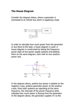
The house diagram is used to calculate the power flow from a generator connected to an infinite bus supplying a load. A house diagram plots the frequency-power relationships of the generator and bus on the same axes, with positive bus power on the negative x-axis and positive generator power on the positive x-axis. The intercept of the plots indicates the power PG supplied by the generator to the bus and load. If the load demand is greater than PG, additional power Pbus is drawn from the bus such that Pload = PG + Pbus. For the generator to supply positive power, its no-load frequency must be greater than the system frequency.

Recommended
More Related Content
What's hot
What's hot (20)
Viewers also liked
Viewers also liked (15)
Similar to House diagram concept
Similar to House diagram concept (20)
Recently uploaded
Recently uploaded (20)
House diagram concept
- 1. The House Diagram Consider the diagram below, where a generator is connected to an infinite bus which is supplying a load. In order to calculate how much power from the generator or bus flows to the load, a house diagram is used. A house diagram is constructed by taking the frequency- power plots of two power supply systems and plotting them on the same diagram, each with its own positive power axis. In the diagram above, positive bus power is plotted on the negative x-axis, positive generator power on the positive x-axis. Since both systems are operating at the same frequency, the intercept of the power-frequency plots indicates how much power is flowing from the generator. In the diagram above, the generator supplies PG to the
- 2. combined bus and load. Since the load power demand is greater than the power supplied by the generator, additional power Pbus is taken from the bus. The bus power can be found using Pload=PG+Pbus In the case that the generator is supplying more power than is required by the load, the excess power will flow to the bus and the value of Pbus in the above equation will be negative. It is important to note in the diagram above that the generator no load frequency is greater than the system frequency. fnl>fsys As the generator frequency falls when the power flow is increased, the no-load frequency must be greater than the system frequency in order for the generator to supply positive power. In the diagram below, the no load frequency is too low and the generator power is negative, i.e. the synchronous machine is operating like a motor. The effect illustrated above is the reason why the frequency of an oncoming generator must be higher than the existing system frequency when connecting generators to a power grid. Most generators automatically detect negative power flow and disconnect from the grid when this situation occurs.
- 3. ASWAN UNIVERSITY FACULTY OF ENGINEERING ELECTRICAL ENGINEERING DEPARTMENT engineer: Ahmed Amin Hassan Slides About " house diagram concept "