
Recommended
More Related Content
What's hot
What's hot (20)
Similar to Air brake system
Similar to Air brake system (20)
Recently uploaded
Recently uploaded (20)
Air brake system
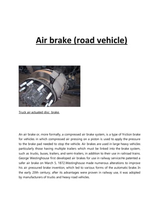
- 1. Air brake (road vehicle) Truck air actuated disc brake. An air brake or, more formally, a compressed air brake system, is a type of friction brake for vehicles in which compressed air pressing on a piston is used to apply the pressure to the brake pad needed to stop the vehicle. Air brakes are used in large heavy vehicles particularly those having multiple trailers which must be linked into the brake system, such as trucks, buses, trailers, and semi-trailers, in addition to their use in railroad trains. George Westinghouse first developed air brakes for use in railway service.He patented a safer air brake on March 5, 1872.Westinghouse made numerous alterations to improve his air pressured brake invention, which led to various forms of the automatic brake. In the early 20th century, after its advantages were proven in railway use, it was adopted by manufacturers of trucks and heavy road vehicles.
- 2. Design and function Air brake systems are typically used on heavy trucks and buses. The system consists of service brakes, parking brakes, a control pedal, and an air storage tank. For the parking brake, there is a disc or drum arrangement which is designed to be held in the 'applied' position by spring pressure. Air pressure must be produced to release these "spring brake" parking Design and function brakes. For the service brakes (the ones used while driving for slowing or stopping) to be applied, the brake pedal is pushed, routing the air under pressure (approx 100–120 psi or 690–830 kPa or 6.89–8.27 bar) to the brake chamber, causing the brake to be engaged. Most types of truck air brakes are drum brakes, though there is an increasing trend towards the use of disc brakes. The air compressor draws filtered air from the atmosphere and forces it into high-pressure reservoirs at around 120 psi (830 kPa; 8.3 bar). Most heavy vehicles have a gauge within the driver's view, indicating the availability of air pressure for safe vehicle operation, often including warning tones or lights. A mechanical "wig wag" that automatically drops down into the driver's field of vision when the pressure drops below a certain point is also common. Setting of the parking/emergency brake releases the pressurized air in the lines between the compressed air storage tank and the brakes, thus allowing the spring actuated parking brake to engage. A sudden loss of air pressure would result in full spring brake pressure immediately. A compressed air brake system is divided into a supply system and a control system. The supply system compresses,stores and supplies high-pressure air to the control system as well as to additional air operated auxiliary truck systems (gearbox shift control, clutch pedal air assistance servo, etc.). Supply system
- 3. Highly simplified air brake diagram on a commercial road vehicle ( does not show all air reservoirs and all applicable air valves ). The air compressor is driven by the engine either by crankshaft pulley via a belt or directly from the engine timing gears. It is lubricated and cooled by the engine lubrication and cooling systems. Compressed air is first routed through a cooling coil and into an air dryer which removes moisture and oil impurities and also may include a pressure regulator, safety valve and smaller purge reservoir. As an alternative to the air dryer, the supply system can be equipped with an anti-freeze device and oil separator. The compressed air is then stored in a supply reservoir (also called a wet tank) from which it is then distributed via a four-way protection valve into the primary reservoir (rear brake reservoir) and the secondary reservoir (front/trailer brake reservoir), a parking brake reservoir, and an auxiliary air supply distribution point. The system also includes various check, pressure limiting, drain and safety valves.Air brake systems may include a wig wag device which deploys to warn the driver if the system air pressure drops too low. Control system The control system is further divided into two service brake circuits, the parking brake circuit, and the trailer brake circuit. The dual service brake circuits are further split into front and rear wheel circuits which receive compressed air from their individual reservoirs for added safety in case of an air leak. The service brakes are applied by means of a brake pedal air valve which regulates both circuits. The parking brake is the air operated spring brake type where its applied by spring force in the spring brake cylinder and released by compressed air via a hand control valve. The trailer brake consists of a direct two line system: the supply line (marked red) and the separate control or service line (marked blue). The supply line receives air from the prime mover park brake air tank via a park brake relay valve and the control line is regulated via the trailer brake relay valve. The operating signals for the relay are provided by the prime mover brake pedal air valve, trailer service brake hand control (subject to local heavy vehicle legislation) and the prime mover park brake hand control.
- 4. Trailer Control Valve Spring brake air cylinder Air brake foot valve Trailer brake relay valve Truck air compressor Electronic air dryer
- 5. Air brakes relay valve Four way protection valve Advantages Air brakes are used as an alternative to hydraulic brakes which are used on lighter vehicles such as automobiles. Hydraulic brakes use a liquid (hydraulic fluid) to transfer pressure from the brake pedal to the brake shoe to stop the vehicle. Air brakes are used in heavy commercial vehicles due to their reliability. They have several advantages for large multi-trailer vehicles: The supply of air is unlimited, so the brake system can never run out of its operating fluid, as hydraulic brakes can. Minor leaks do not result in brake failures. Air line couplings are easier to attach and detach than hydraulic lines; the risk of air getting into hydraulic fluid is eliminated, as is the need to bleed brakes when they are serviced. Air brake circuits on trailers can be easily attached and removed. Air not only serves as a fluid for transmission of force, but also stores potential energy as it is compressed, so it can serve to control the force applied; hydraulic fluid is nearly incompressible. Air brake systems include an air tank that stores sufficient energy to stop the vehicle if the compressor fails. Air brakes are effective even with considerable leakage, so an air brake system can be designed with sufficient "fail-safe" capacity to stop the vehicle safely even when leaking.
- 6. Disadvantages Although air brakes are readily considered the superior braking system for heavy vehicles, generally those with a maximum gross vehicle weight rating (GVWR) of 26,000 to 33,000 pounds or more, which would over load hydraulic brakes, they also have the following disadvantages, when compared to hydraulic braking systems: Air brakes generally cost more. Air brake systems compress air, which results in moisture that requires air dryers to remove, which also increases the price for air brake systems and can contribute to higher maintenance and repair costs, particularly in the first five years. In the U.S. commercial drivers are required to obtain additional training and licensing, known as an “endorsement,” in order to legally drive any vehicle using an air brake system. The Federal Motor Carrier Safety Administration (FMCSA), which regulates the trucking industry in the U.S., requires that drivers who operate a vehicle equipped with air brakes take their driving test in one. Learning to operate air brakes smoothly has a learning curve, as they are difficult to operate smoothly. Also, since air brakes must be operated differently from hydraulic systems, driving a vehicle with air brakes requires knowledge of proper maintenance. A driver is required to inspect the air pressurization system prior to driving and make sure all tanks are in working order. As noted by the Insurance Corporation of British Columbia (ICBC), “Operating commercial vehicles or vehicles equipped with air brakes requires special knowledge and skill, and the cost of a mistake can be very high. When large vehicles are involved in crashes, the damage—to vehicles, cargo and human lives—can be catastrophic. THE COMPONENTS OF AN AIR BRAKE SYSTEM A basic air brake system capable of stopping a vehicle has five main components: 1. A COMPRESSOR, to pump air 2. A RESERVOIR OR TANK, to store the compressed air 3. A FOOT VALVE, to regulate the flow of compressed air
- 7. from the reservoir when it is needed for braking 4. BRAKE CHAMBERS & SLACK ADJUSTERS, the means of transferring the force exerted by the compressed air to mechanical linkages 5. BRAKE LININGS AND DRUM OR ROTORS, to create the friction required to stop the wheels It is necessary to understand how each of these components works before studying their functions in the air brake system . 1. Air Compressor An air compressor maintains the proper level of air pressure so that the air brakes and any other air-powered accessories operate safely and consistently. Depending on the make and model of your heavy truck, its compressor is either gear or belt-driven and gets cooled by either air or an engine cooling system. The compressor(s) startup every time the engine is triggered, and the device loads and unloads air which is pumped in and out of the reservoirs and the other two-cylinder compressors. 2. Reservoirs In the case of heavy truck and bus air brake systems, it’s the reservoirs that hold onto a sufficient amount of compressed air, until the supply is required for braking. Note: drivers cannot control the amount of air that they use when the air brakes are triggered; the amount solely depends on how much has been circulated by the compressor.In terms of design, reservoirs are pressure-rated tanks that feature special drain valves called draincocks. When the draincocks are in the ‘open’ position, they drain themselves of any moisture or pollutants that might compromise the integrity of the air. 3. Foot Valve The foot valve, otherwise known as the treadle or the brake pedal, is the tool that determines the volume of air pressure used. In this case, the volume is determined by how hard the operator presses their footon the foot valve.When the compressed air is released through the brake system, it takes time for it to be produced again through the compressor function (described above). That said, if too much pressure is released in a short period of time, the entire system could fail.
- 8. 4. Brake Chambers Brake chambers, otherwise known as brake pots, are the devices that turn the compressed air into mechanical force. It is through this mechanism that the brakes are triggered and the heavy truck or bus is able to safely halt. Each one of the brake chambers comes equipped with a specific pushrod stroke adjustment limit. The chamber itself is held together by a clamp assembly that is specially made to regulate the compressed air that is released into the chambers. 5. Brake Shoes and Drums By making use of friction, the brake shoes – or pads, depending on the make and model of the truck – are forced outwards, thus initiating the air brake system.A special brake lining material is attached to the brake shoes to help promote consistency. If the type of lining is a good fit, it should also regulate heat that is created from the friction. Using Air Brakes Normal Stops To apply the air brakes during normal stops, push the brake pedal down. Control the pressure so the vehicle comes to a smooth, safe stop. If you have a manual transmission, do not push the clutch in until the engine RPM is down close to idle. When stopped, select a starting gear. Emergency Stops If somebody suddenly pulls out in front of you, your natural response is to hit the brakes. This is a good response if there is enough distance to stop and you use the brakes correctly You should brake in a way that will keep your vehicle in a straight line and allow you to turn if it becomes necessary. You can use the “controlled braking” method or the “stab braking” method. Controlled braking: With this method, you apply the brakes as hard as you can without locking the wheels. Keep steering wheel movements very small while doing this. If you need to make larger
- 9. steering adjustments or if the wheels lock, release the brakes. Reapply the brakes as soon as you can. Stab braking: Use only on vehicles without anti-lock systems. Apply the brake all the way. Release the brakes when the wheels lock up. As soon as the wheels start rolling, put on the brakes fully again. It can take up to 1 second for the wheels to start rolling after you release the brakes. If you reapply the brakes before the wheels start rolling, the vehicle will not straighten out. Anti-lock Brakes New trucks and truck-trailer vehicles are equipped with anti-lock brakes. The anti-lock braking system is different than the normal air-brake system but works on the same principle.Vehicles that have anti-lock brakes have a yellow light near the driverʼs rear side of the vehicle with the letters ABS stenciled above the light. Once the driver turns on the ignition, a yellow malfunction lamp on the instrument panel will light up, briefly indicating that the vehicle has anti-lock brakes. This lamp will remain constant if there is a malfunction in the anti-lock brake system.For normal or emergency stopping using anti-lock brakes, the driverʼs foot remains on the brake pedal in which the anti-lock module then acts as a foot pumping the air brake system. On the air-brake system the driver must pump or use stab braking in an emergency. If the anti-lock brake system fails or malfunctions, the driver must resort to stopping the vehicle by using the normal air-brake method. If an emergency arises, the driver should use the controlled or stab braking method. The anti-lock brake system should be serviced as soon as possible. Stopping Distance Stopping distance was discussed in Section 2: Speed and Stopping Distance. With air brakes, there is an added delay – the time required for the brakes to work after the brake pedal is pushed. With hydraulic brakes (used on cars and light /medium trucks), the brakes work instantly. However, with air brakes, it takes a little time (one-half second or more) for the air to flow through the lines to the brakes. Thus, the total stopping distance for vehicles with air brake systems is made up of four different factors:
- 10. Perception Distance + Reaction Distance + Brake Lag Distance + Effective Braking Distance ------------------------------ = Total Stopping Distance The air brake lag distance at 55 mph on dry pavement adds about 32 feet. Therefore, for an average driver traveling 55 mph under good traction and brake conditions, the total stopping distance is more than 300 feet.