SlideShare a Scribd company logo
1 of 27
Download to read offline
184
AIR SYSTEM AND BRAKES
Two separate brake systems are used on the 793D trucks. The two brake systems are: the
parking/secondary brake system and the service/retarder brake system.
The parking/secondary brakes are spring engaged and hydraulically released. The
service/retarder brakes are engaged hydraulically by an air-over-oil brake system.
The 793D trucks are also equipped with an air system. An engine driven air compressor
supplies the air and fills two tanks. Air from the tanks provides energy to perform several
functions:
- Engine start-up
- Service and retarder brake control
- Secondary and parking brake control
- Automatic lubrication injection (grease)
- Horn, air seat, and cab clean-out
- Exhaust bypass (wastegate) control
SERV1817-01 - 236 - Text Reference
08/06
Shown is a cutaway illustration of an oil cooled brake assembly. The brakes are
environmentally sealed and adjustment free. Oil continually flows through the brake discs for
cooling. Duo-Cone seals prevent the cooling oil from leaking to the ground or transferring into
the axle housing. The wheel bearing adjustment must be maintained to keep the Duo-Cone seals
from leaking.
The smaller piston (yellow) is used to ENGAGE the secondary and parking brakes. The parking
brakes are spring ENGAGED and hydraulically RELEASED.
The larger piston (purple) is used to ENGAGE the retarder/service brakes. The retarder/service
brakes are engaged hydraulically by an air-over-oil brake system.
185
SERV1817-01 - 237 - Text Reference
08/06
186
Air Charging System
This schematic shows the flow of air through the air charging system. Air flows from the air
compressor, through the air dryer, to the service/retarder brake tank.
Air from the service/retarder brake tank enters the pressure protection valve. When the pressure
in the service/retarder tank reaches 550 kPa (80 psi), the pressure protection valve allows air to
flow to the parking/secondary brake tank, the air start system, the engine wastegate valve, the
automatic lubrication system, and the accessory circuits (horn, air seat, and cab clean-out).
All tanks have a check valve at the air supply port to prevent a loss of air if a leak upstream of
the tank occurs.
SERV1817-01 - 238 - Text Reference
08/06
The air system is charged by an air compressor mounted on the left front of the engine. To
handle the increased air flow, a large air dryer is used, and the hoses and tubing have also been
increased in size.
System pressure is controlled by the governor (arrow). The governor maintains the system
pressure between 660 and 830 kPa (95 and 120 psi). The governor setting can be adjusted with
a screw below the cover on the governor. Turn the adjustment screw OUT to increase the
pressure and IN to decrease the pressure.
The air compressor is lubricated with engine oil and cooled with aftercooler coolant.
To test the air compressor efficiency, lower the air system pressure to 480 kPa (70 psi). Start the
engine and raise the engine speed to HIGH IDLE. When the air system pressure reaches
585 kPa (85 psi), measure the time that it takes to build system pressure from 585 kPa (85 psi) to
690 kPa (100 psi). The time to raise the pressure should be 50 seconds or less. If the time
recorded is greater than 50 seconds, check for leaks or a restriction in the system. If no leaks or
restrictions are found, the air compressor may have a problem.
187
SERV1817-01 - 239 - Text Reference
08/06
Air flows from the air compressor to the air dryer (arrow) located in front of the left front tire.
The air system can be charged from a remote air supply through a ground level connector inside
the left frame.
The air dryer removes contaminants and moisture from the air system. The condition of the
desiccant in the air dryer should be checked every 250 hours and changed periodically
(determined by the humidity of the local climate).
When the air compressor governor senses that system air pressure is at the cut-out pressure of
830 kPa (120 psi), the governor sends an air pressure signal to the purge valve in the bottom of
the dryers. The purge valve opens and air pressure that is trapped in the air dryer is exhausted
through the desiccant, an oil filter, and the purge valve.
An air system relief valve is located on the air dryers to protect the system if the air compressor
governor malfunctions.
A heating element in the bottom of the dryer prevents moisture in the dryer from freezing in cold
weather.
188
SERV1817-01 - 240 - Text Reference
08/06
Air flows through the air dryer and fills two tanks. The service/retarder brake tank (1) is located
on the right platform. This tank also supplies air for the air start system.
The second tank is located behind the cab and supplies air for the parking/secondary brake
system.
A relief valve (2) protects the air system when the air dryer has exhausted and the ball check
valves in the air dryer outlet port closes. The check valves separate the air system from the air
dryer relief valves.
Condensation should be drained from the tank daily through the drain valve (3).
189
SERV1817-01 - 241 - Text Reference
08/06
Located behind the operator’s station is a pressure protection valve (1). Supply air flows from
the large service/retarder brake tank, through the pressure protection valve, to the secondary air
system and accessories. The pressure protection valve opens at 550 kPa (80 psi) and closes at
482 kPa (70 psi). If the secondary air lines or an accessory circuit fails, the pressure protection
valve maintains a minimum of 482 kPa (70 psi) in the service/retarder brake circuit.
To test the pressure protection valve, drain the air pressure to approximately 345 kPa (50 psi).
Use the VIMS display to observe the brake air pressure. With the engine running at LOW
IDLE, press the horn button. Record the air pressure when the horn sounds. This pressure
reading is the open setting of the pressure protection valve. Slowly drain the air pressure and
record the air pressure when the horn turns off. This pressure reading is the setting of the
pressure protection valve when it closes.
The air system pressure sensor (2) provides an input signal to the Brake ECM. The Brake ECM
sends a signal to the VIMS, which informs the operator if a problem exists in the air system.
Also located behind the operator’s station are the service/retarder brake switch, the
parking/secondary brake switch, and the brake light switch (see Visual No. 141).
190
SERV1817-01 - 242 - Text Reference
08/06
Located behind the operator’s station is the parking/secondary brake air tank. A drain valve is
located on the right side of the cab. Moisture should be drained from the tank daily through the
drain valve (see Visual No. 32).
A check valve (arrow) prevents a loss of air if an air line breaks upstream of the air tank.
191
SERV1817-01 - 243 - Text Reference
08/06
192
Brake Systems
This schematic shows the flow of air through the service/retarder brake air system when the
retarder (manual and automatic) is RELEASED, and the service brakes are ENGAGED. Supply
air pressure flows from the large service brake air tank to the relay valves and the service brake
valve and manual retarder valve.
The manual retarder valve blocks the flow of air. The service brake valve allows air to flow to
the double check valve that blocks the passage to the manual retarder. Air pressure from the
service brake valve flows through the double check valve to the service brake relay valve.
The service brake relay valve opens and metered air flows from the large service brake air tank
to the brake cylinders. The relay valves reduce the time required to engage and release the
brakes.
Air from the service brake valve also flows to the brake light switch and the service/retarder
switch. Depressing the service brake pedal turns ON the brake lights and changes the
transmission shift points and anti-hunt timer.
SERV1817-01 - 244 - Text Reference
08/06
When the manual retarder lever is moved, air flows through the double check valve that blocks
the passage to the service brake valve. Air pressure from the manual retarder brake valve flows
through the double check valve to the service brake relay valve.
Air from the manual retarder brake valve also flows to the retarder switch, the brake light switch
and the service/retarder switch. Engaging the manual retarder turns ON the retarder dash lamp,
the brake lights, and changes the transmission shift points and anti-hunt timer.
SERV1817-01 - 245 - Text Reference
08/06
193
Shown is the parking/secondary brake hydraulic and air system with the secondary brakes
RELEASED and the parking brakes ENGAGED.
Supply air from the parking/secondary brake air tank flows to the secondary brake valve and is
blocked from flowing to the inverter valve signal port. Supply air is allowed to flow through the
inverter valve and is blocked by the parking brake air valve.
No air pressure is present to move the spool in the parking brake release valve. Supply oil from
the parking brake release pump is blocked by the spool. Oil from the parking brake is open to
drain through the parking brake release valve, which allows the springs in the parking brake to
ENGAGE the brakes.
A parking/secondary brake switch is located in the air line between the parking brake valve and
the parking brake release valve. The switch provides an input signal to the
Transmission/Chassis ECM. When the parking or secondary brakes are ENGAGED, the switch
signals the Transmission/Chassis ECM to allow rapid downshifts.
SERV1817-01 - 246 - Text Reference
08/06
The manual retarder valve (arrow) is controlled by the retarder lever in the cab. Normally, the
retarder valve blocks air flow to the service brake relay valve near the brake master cylinders.
When the retarder lever is pulled down, air flows to the service brake relay valve [maximum
pressure is approximately 550 kPa (80 psi)]. The retarder lever is used to modulate the service
brake engagement by metering the amount of air flow to the service brake relay valve.
The retarder engages the same brakes as the service brake pedal (see Visual No. 43), but is easier
to control for brake modulation.
The retarder system allows the machine to maintain a constant speed on long downgrades. The
retarder will not apply all of the normal braking capacity.
NOTICE
Do not use the retarder control as a parking brake or to stop the machine.
194
SERV1817-01 - 247 - Text Reference
08/06
The service brake valve (1) is controlled by the brake pedal in the cab. Supply air for the service
brake valve and the manual retarder valve is supplied from the manifold (3).
When the service brakes are engaged, air flows from the service brake valve to the service brake
relay valve near the brake master cylinders [maximum pressure is 825 kPa (120 psi)].
The service brake valve engages the same brakes as the retarder, but does not control brake
modulation as precisely as the retarder.
Air from the service brake valve and the manual retarder valve flows through the double check
valve (4) to the service brake relay valve. If the manual retarder and the service brakes are
engaged at the same time, air from the system with the highest pressure will flow through the
double check valve to the service brake relay valve.
Air from the manual retarder valve also flows through the retarder switch (5) to the double check
valve (4). The retarder switch turns on the amber retarder lamp on the dash in the operator’s
station when the manual retarder is ENGAGED.
The brake light switch and the service/retarder brake switch (see Visual No. 141) are located in
the supply line to the front brake oil cooler diverter valve (see Visual No. 211). The service
brake valve, the manual retarder valve and the Automatic Retarder Control (ARC) valve send air
to these switches when engaged.
195
SERV1817-01 - 248 - Text Reference
08/06
The secondary brake valve (2) is controlled by the red pedal in the cab (see Visual No. 43).
When the secondary brakes are engaged, air flows from the secondary brake valve to the signal
port of an inverter valve (see next visual). The inverter valve then blocks the flow of air from
the secondary brake tank to the brake release valve (see Visual No. 199).
Blocking the air from the brake release valve positions the spool in the brake release valve to
drain the oil from the parking brakes, which allows the springs in the parking brake to
ENGAGE the brakes. The secondary brake valve can be used to modulate parking brake
engagement by metering the amount of air flow to the brake release valve.
The parking brake air valve (see Visual No. 44) on the shift console in the cab also controls the
flow of air to the brake release valve, but the parking brake air valve does not modulate the
parking brake application.
The parking/secondary brake switch (see Visual No. 141) is located in the supply line to the
brake release valve. The secondary brake valve and the parking brake air valve send air to this
switch when engaged.
INSTRUCTOR NOTE: The ARC system will be discussed in more detail later in this
presentation.
SERV1817-01 - 249 - Text Reference
08/06
When the secondary brakes are engaged, air flows from the secondary brake valve to the signal
port (1) of the inverter valve (2). The inverter valve then blocks the flow of air from the
secondary brake tank to the brake release valve.
Blocking the air from the brake release valve positions the spool in the brake release valve to
drain the oil from the parking brakes, which allows the springs in the parking brake to ENGAGE
the brakes.
196
SERV1817-01 - 250 - Text Reference
08/06
Shown is the parking brake release pump (arrow). Oil flows from the brake release pump
through the brake release filter to the brake release valve.
197
SERV1817-01 - 251 - Text Reference
08/06
Oil flows from the parking brake release pump, through the parking brake release filter (1), to
the parking brake release valve. An oil filter bypass switch (2) is located on the filter housing.
The oil filter bypass switch provides an input signal to the Brake ECM. The Brake ECM sends
the signal to the VIMS, which informs the operator if the filter is restricted.
Also shown are the rear brake oil coolers (3). Oil flows from the rear brake cooling pump and
the brake oil cooling filter from the hoist valve, through two screens and the two rear brake oil
coolers to the rear brakes.
198
SERV1817-01 - 252 - Text Reference
08/06
Oil from the parking brake release pump flows through the parking brake release filter to the
brake release valve (1) located inside the right rear frame. Oil flows from the parking brake
release valve to the parking brake piston in the brakes when the parking brakes are released.
Supply air from the parking brake air valve in the cab or the secondary brake valve flows
through the small hose (2) to an air chamber in the brake release valve. The brake release valve
contains an air piston that moves a spool. The spool either directs oil to RELEASE the parking
brakes or drains oil to ENGAGE the parking brakes. A relief valve (3) in the brake release valve
limits the system pressure for releasing the brakes. The setting of the relief valve is 4700 ± 200
kPa (680 ± 30 psi).
Supply oil flows from the brake release valve through an orifice and a screen (4) to the brake oil
makeup tank. If the makeup tank is not receiving proper flow of oil, remove and check the
orifice and screen (4) for plugging.
To release the parking brakes for service work or towing, the electric motor that turns the towing
pump (5) can be energized by the brake release switch located in the cab (see Visual No. 48).
The pump sends oil to the brake release valve to RELEASE the parking brakes. Towing pump
pressure is controlled by a relief valve in the towing pump.
199
SERV1817-01 - 253 - Text Reference
08/06
200
Normally, supply oil flows from the parking brake release pump, through the parking brake
release filter, to the parking brake release valve. If air pressure is present from the parking brake
air valve or the secondary brake valve, supply oil flows past the relief valve, the check valve,
and the spool to RELEASE the parking brakes. The relief valve limits the system pressure for
releasing the brakes and for the pilot oil to shift the hoist valve. The setting of the relief valve in
the parking brake valve is 4700 ± 200 kPa (680 ± 30 psi).
This schematic shows the flow of oil through the parking brake release system when the towing
system is activated.
Oil flow from the parking brake release pump has stopped. The towing motor is energized, and
air pressure is present above the parking brake release valve piston. The air pressure moves the
spool in the parking brake release valve down to block the drain port.
Oil flows from the towing pump to the parking brake release valve and the parking brakes. The
check valve to the right of the parking brake release filter blocks the oil from the towing pump
from flowing to the parking brake release pump.
SERV1817-01 - 254 - Text Reference
08/06
During towing, the parking brake release pressure is limited by a relief valve in the towing
pump. When the relief valve opens, oil transfers from the pressure side to the suction side of the
towing pump. The setting of the relief valve is approximately 4480 kPa (650 psi).
A check valve in the outlet port of the towing pump prevents oil from flowing to the towing
pump during normal operation.
To check the brake release system used for towing, connect a gauge to the parking brake release
pressure tap on the rear axle (see Visual No. 204). Use a long gauge hose so the gauge can be
held in the cab. With the parking brake air valve in the RELEASE position and the key start
switch in the ON position, energize the parking brake release switch used for towing (on the
dash). The parking brake release pressure should increase to 4480 kPa (650 psi). Turn off the
switch when the pressure stops increasing.
The parking brake release pressure must increase to a minimum of 3790 kPa (550 psi). The
parking brakes start to release between 3100 and 3445 kPa (450 and 500 psi). During towing,
the brake release switch on the dash must be energized whenever the parking brake release
pressure decreases below this level or the brakes will drag. The parking brakes are fully
released between 3445 and 3860 kPa (500 and 560 psi).
NOTE: A minimum of 550 kPa (80 psi) air pressure must be available at the parking
brake release valve to ensure full release of the brakes for towing.
NOTICE
Activate the brake release switch only when additional pressure is required to release the
brakes. Leaving the brake release (towing) motor energized continuously will drain the
batteries.
The parking brake release pressure setting must not exceed 5445 kPa (790 psi). Exceeding
this pressure can cause internal damage to the brake assembly.
SERV1817-01 - 255 - Text Reference
08/06
The front service brake relay valve (1) receives metered air from only the service brake valve or
the manual retarder valve.
When the service brakes or manual retarder brakes are ENGAGED, the front relay valve opens
and metered air flows from the service brake reservoir to the four brake cylinders (2) (2 shown).
The brake relay valves reduce the time required to engage and release the brakes.
The brake cylinders operate by air-over-oil. When the metered air enters the brake cylinders, a
piston moves down and pressurizes the oil in the bottom of the cylinders. Two brake cylinders
supply oil to the front brakes and two brake cylinders supply oil to the rear brakes.
201
SERV1817-01 - 256 - Text Reference
08/06
As the brake discs in the brake assemblies wear, more oil is needed from the brake cylinders to
compensate for the wear. The makeup oil tank (1) supplies makeup oil for the brake cylinders.
Oil from the parking brake release valve flows through an orifice and screen to provide a
continuous supply of oil to the makeup tank. Low flow to the makeup tank can cause the
makeup oil reserve to decrease and cause the brake cylinders to overstroke.
To check for makeup oil flow, remove the cover from the makeup oil tank. With the engine at
HIGH IDLE, a stream of oil filling the tank should be visible. If a stream of oil is not visible,
there may be a restriction in the filter or hose to the tank or pump flow may be low.
Keep the service brake ENGAGED for at least one minute. If air is in the system or a loss of oil
downstream from the cylinders occurs, the piston in the cylinder will overstroke and cause an
indicator rod to extend and open the brake overstroke switch (2). The switch provides an input
signal to the Brake ECM. The Brake ECM sends the signal to the VIMS, which informs the
operator of the condition of the service/retarder brake oil circuit. If an overstroke condition
occurs, the problem must be repaired and the indicator rod pushed in to end the warning.
202
SERV1817-01 - 257 - Text Reference
08/06
The oil-to-air ratio of the brake cylinder is approximately 6.6 to 1. To test the brake cylinder,
install a gauge in the fitting on top of the brake cylinder and a gauge on the pressure tap on the
slack adjuster. When the service brakes are ENGAGED, if the air pressure in the brake cylinder
is 690 kPa (100 psi), the oil pressure measured at the slack adjuster should be approximately
4560 kPa (660 psi). When the brakes are RELEASED, both pressures should return to zero.
Inspect the condition of the breather for the brake cylinders (see Visual No. 21). Oil should not
leak from the breather. Oil leaking from the breather is an indication that the oil piston seals in a
brake cylinder needs replacement. Air flow from the breather during a brake application is an
indication that a brake cylinder air piston seal needs replacement.
Shown is one of the four brake oil temperature sensors (3). Four brake oil temperature sensors,
one for each brake, are located in the brake oil cooling tubes. The brake oil temperature sensors
provide input signals to the VIMS, which keeps the operator informed of the brake cooling oil
temperature.
The most common cause of high brake cooling oil temperature is operating a truck in a gear that
is too high for the grade and not maintaining sufficient engine speed. Engine speed should be
kept at approximately 1900 rpm during long downhill hauls.
Also, make sure the pistons in the slack adjuster are not stuck and retaining too much pressure
on the brakes (see Visuals No. 204 and 205).
SERV1817-01 - 258 - Text Reference
08/06
203
This visual shows a sectional view of the brake cylinder when the brakes are ENGAGED.
Air pressure from the brake relay valve enters the air inlet. The air pressure moves the air piston
and the attached rod closes the valve in the oil piston. When the valve in the oil piston is closed,
the oil piston pressurizes the oil in the cylinder. The pressure oil flows to the slack adjuster.
If air is in the system or a loss of oil downstream from the cylinders occurs, the piston in the
cylinder will overstroke, which causes the indicator rod to extend and open the brake overstroke
switch. If an overstroke condition occurs, the problem must be repaired and the indicator rod
pushed in to end the warning.
When the air pressure is removed from behind the air piston, the spring moves the air piston and
the attached rod opens the valve in the oil piston. Any makeup oil that is needed flows into the
passage at the top of the oil chamber, through the valve, and into the oil chamber at the right of
the oil piston.
SERV1817-01 - 259 - Text Reference
08/06
The truck is equipped with two slack adjusters. One of the slack adjusters is for the front brakes
and one is for the rear brakes. The slack adjuster (1) shown is for the rear brakes. The slack
adjusters compensate for brake disc wear by allowing a small volume of oil to flow through the
slack adjuster and remain between the slack adjuster and the brake piston under low pressure.
The slack adjusters maintain a slight pressure on the brake piston at all times.
Brake cooling oil pressure maintains a small clearance between the brake discs.
The service brake oil pressure can be measured at the two taps (2) located on top of the slack
adjusters.
Air can be removed from the service brakes through the two remote bleed valves (3) (one
shown).
The parking brake release pressure can be measured at the two taps (4) (one shown) on the axle
housing.
NOTE: Air can be removed from the front service brakes through bleed valves located
on each wheel.
204
SERV1817-01 - 260 - Text Reference
08/06
205
This visual shows sectional views of the slack adjuster when the brakes are RELEASED and
ENGAGED.
When the brakes are ENGAGED, oil from the brake cylinders enters the slack adjusters and the
two large pistons move outward. Each large piston supplies oil to one wheel brake. The large
pistons pressurize the oil to the service brake pistons and ENGAGE the brakes.
Normally, the service brakes are FULLY ENGAGED before the large pistons in the slack
adjusters reach the end of their stroke. As the brake discs wear, the service brake piston will
travel farther to FULLY ENGAGE the brakes. When the service brake piston travels farther, the
large piston in the slack adjuster moves farther out and contacts the end cover. The pressure in
the slack adjuster increases until the small piston moves and allows makeup oil from the brake
cylinders to flow to the service brake piston.
When the brakes are RELEASED, the springs in the service brakes push the service brake
pistons away from the brake discs. The oil from the service brake pistons pushes the large
pistons in the slack adjuster to the center of the slack adjuster. Makeup oil that was used to
ENGAGE the brakes is replenished at the brake cylinders from the makeup tank.
SERV1817-01 - 261 - Text Reference
08/06
The spring behind the large piston causes some oil pressure to be felt on the service brake piston
when the brakes are RELEASED (residual pressure). Keeping some pressure on the brake
piston provides rapid brake engagement with a minimum amount of brake cylinder piston travel.
The slack adjusters can be checked for correct operation by opening the service brake bleed
screw with the brakes RELEASED. A small amount of oil should flow from the bleed screw
when the screw is opened. The small flow of oil verifies that the spring behind the large piston
in the slack adjuster is maintaining some pressure on the service brake piston.
Another check to verify correct slack adjuster operation is to connect a gauge to the pressure tap
on top of the slack adjuster and another gauge at the service brake bleed screw location. With
system air pressure at maximum and the service brake pedal depressed, the pressure reading on
both gauges should be approximately the same.
When the brakes are RELEASED, the pressure at the slack adjuster should return to zero. The
pressure at the service brake bleed screw location should return to the residual pressure held on
the brakes by the slack adjuster piston.
The residual pressures at the service brake bleed screw location should be:
Front: 59 kPa (8.6 psi) Rear: 68 kPa (9.9 psi)
Low residual pressure may indicate a failed slack adjuster. High residual pressure may also
indicate a failed slack adjuster or warped brake discs. To check for warped brake discs, rotate
the wheel to see if the pressure fluctuates. If the pressure fluctuates while rotating the wheel, the
brake discs are probably warped and should be replaced.
To check for brake cooling oil leakage, block the brake cooling ports and pressurize each brake
assembly to a maximum of 138 kPa (20 psi). Close off the air supply source and observe the
pressure trapped in the brake assembly for five minutes. The trapped pressure should not
decrease.
SERV1817-01 - 262 - Text Reference
08/06

More Related Content

Similar to SISTEMA DE AIRE FRENOS 793D

YALE F876 GDP230DCS LIFT TRUCK Service Repair Manual
YALE F876 GDP230DCS LIFT TRUCK Service Repair ManualYALE F876 GDP230DCS LIFT TRUCK Service Repair Manual
YALE F876 GDP230DCS LIFT TRUCK Service Repair Manualyehnmdm jnkmem
 
YALE F877 GDP300EC LIFT TRUCK Service Repair Manual
YALE F877 GDP300EC LIFT TRUCK Service Repair ManualYALE F877 GDP300EC LIFT TRUCK Service Repair Manual
YALE F877 GDP300EC LIFT TRUCK Service Repair Manualuhsejmkm jksemmd
 
Air brake system
Air brake systemAir brake system
Air brake systemaadiiaadil
 
ATA 21.pdf
ATA 21.pdfATA 21.pdf
ATA 21.pdfTate40
 
Pneumatic system
Pneumatic systemPneumatic system
Pneumatic systemDarknes Steven
 
H60
H60H60
H60toru101
 
Automobile - AC SYSTEM
Automobile - AC SYSTEMAutomobile - AC SYSTEM
Automobile - AC SYSTEMMd. Mydul Islam
 
Halderman ch105 lecture
Halderman ch105 lectureHalderman ch105 lecture
Halderman ch105 lecturemcfalltj
 
New holland t8010 tractor service repair manual
New holland t8010 tractor service repair manualNew holland t8010 tractor service repair manual
New holland t8010 tractor service repair manualfujsjefjkskefksem
 
New holland t8020 tractor service repair manual
New holland t8020 tractor service repair manualNew holland t8020 tractor service repair manual
New holland t8020 tractor service repair manualfujsjfjksekem
 
New holland t8040 tractor service repair manual
New holland t8040 tractor service repair manualNew holland t8040 tractor service repair manual
New holland t8040 tractor service repair manualfijsfjskekmme
 
New Holland T8050 Tractor Service Repair Manual.pdf
New Holland T8050 Tractor Service Repair Manual.pdfNew Holland T8050 Tractor Service Repair Manual.pdf
New Holland T8050 Tractor Service Repair Manual.pdfzui07gang
 
New holland t8030 tractor service repair manual
New holland t8030 tractor service repair manualNew holland t8030 tractor service repair manual
New holland t8030 tractor service repair manualfksjksmmde
 

Similar to SISTEMA DE AIRE FRENOS 793D (15)

YALE F876 GDP230DCS LIFT TRUCK Service Repair Manual
YALE F876 GDP230DCS LIFT TRUCK Service Repair ManualYALE F876 GDP230DCS LIFT TRUCK Service Repair Manual
YALE F876 GDP230DCS LIFT TRUCK Service Repair Manual
 
YALE F877 GDP300EC LIFT TRUCK Service Repair Manual
YALE F877 GDP300EC LIFT TRUCK Service Repair ManualYALE F877 GDP300EC LIFT TRUCK Service Repair Manual
YALE F877 GDP300EC LIFT TRUCK Service Repair Manual
 
Air brake system
Air brake systemAir brake system
Air brake system
 
ATA 21.pdf
ATA 21.pdfATA 21.pdf
ATA 21.pdf
 
Pneumatic system
Pneumatic systemPneumatic system
Pneumatic system
 
H60
H60H60
H60
 
Hst ppt
Hst pptHst ppt
Hst ppt
 
Automobile - AC SYSTEM
Automobile - AC SYSTEMAutomobile - AC SYSTEM
Automobile - AC SYSTEM
 
User manual
User manualUser manual
User manual
 
Halderman ch105 lecture
Halderman ch105 lectureHalderman ch105 lecture
Halderman ch105 lecture
 
New holland t8010 tractor service repair manual
New holland t8010 tractor service repair manualNew holland t8010 tractor service repair manual
New holland t8010 tractor service repair manual
 
New holland t8020 tractor service repair manual
New holland t8020 tractor service repair manualNew holland t8020 tractor service repair manual
New holland t8020 tractor service repair manual
 
New holland t8040 tractor service repair manual
New holland t8040 tractor service repair manualNew holland t8040 tractor service repair manual
New holland t8040 tractor service repair manual
 
New Holland T8050 Tractor Service Repair Manual.pdf
New Holland T8050 Tractor Service Repair Manual.pdfNew Holland T8050 Tractor Service Repair Manual.pdf
New Holland T8050 Tractor Service Repair Manual.pdf
 
New holland t8030 tractor service repair manual
New holland t8030 tractor service repair manualNew holland t8030 tractor service repair manual
New holland t8030 tractor service repair manual
 

Recently uploaded

Arduino_CSE ece ppt for working and principal of arduino.ppt
Arduino_CSE ece ppt for working and principal of arduino.pptArduino_CSE ece ppt for working and principal of arduino.ppt
Arduino_CSE ece ppt for working and principal of arduino.pptSAURABHKUMAR892774
 
Application of Residue Theorem to evaluate real integrations.pptx
Application of Residue Theorem to evaluate real integrations.pptxApplication of Residue Theorem to evaluate real integrations.pptx
Application of Residue Theorem to evaluate real integrations.pptx959SahilShah
 
Artificial-Intelligence-in-Electronics (K).pptx
Artificial-Intelligence-in-Electronics (K).pptxArtificial-Intelligence-in-Electronics (K).pptx
Artificial-Intelligence-in-Electronics (K).pptxbritheesh05
 
Introduction to Machine Learning Unit-3 for II MECH
Introduction to Machine Learning Unit-3 for II MECHIntroduction to Machine Learning Unit-3 for II MECH
Introduction to Machine Learning Unit-3 for II MECHC Sai Kiran
 
Introduction-To-Agricultural-Surveillance-Rover.pptx
Introduction-To-Agricultural-Surveillance-Rover.pptxIntroduction-To-Agricultural-Surveillance-Rover.pptx
Introduction-To-Agricultural-Surveillance-Rover.pptxk795866
 
EduAI - E learning Platform integrated with AI
EduAI - E learning Platform integrated with AIEduAI - E learning Platform integrated with AI
EduAI - E learning Platform integrated with AIkoyaldeepu123
 
GDSC ASEB Gen AI study jams presentation
GDSC ASEB Gen AI study jams presentationGDSC ASEB Gen AI study jams presentation
GDSC ASEB Gen AI study jams presentationGDSCAESB
 
An experimental study in using natural admixture as an alternative for chemic...
An experimental study in using natural admixture as an alternative for chemic...An experimental study in using natural admixture as an alternative for chemic...
An experimental study in using natural admixture as an alternative for chemic...Chandu841456
 
CCS355 Neural Networks & Deep Learning Unit 1 PDF notes with Question bank .pdf
CCS355 Neural Networks & Deep Learning Unit 1 PDF notes with Question bank .pdfCCS355 Neural Networks & Deep Learning Unit 1 PDF notes with Question bank .pdf
CCS355 Neural Networks & Deep Learning Unit 1 PDF notes with Question bank .pdfAsst.prof M.Gokilavani
 
🔝9953056974🔝!!-YOUNG call girls in Rajendra Nagar Escort rvice Shot 2000 nigh...
🔝9953056974🔝!!-YOUNG call girls in Rajendra Nagar Escort rvice Shot 2000 nigh...🔝9953056974🔝!!-YOUNG call girls in Rajendra Nagar Escort rvice Shot 2000 nigh...
🔝9953056974🔝!!-YOUNG call girls in Rajendra Nagar Escort rvice Shot 2000 nigh...9953056974 Low Rate Call Girls In Saket, Delhi NCR
 
Gfe Mayur Vihar Call Girls Service WhatsApp -> 9999965857 Available 24x7 ^ De...
Gfe Mayur Vihar Call Girls Service WhatsApp -> 9999965857 Available 24x7 ^ De...Gfe Mayur Vihar Call Girls Service WhatsApp -> 9999965857 Available 24x7 ^ De...
Gfe Mayur Vihar Call Girls Service WhatsApp -> 9999965857 Available 24x7 ^ De...srsj9000
 
Call Us ≽ 8377877756 ≼ Call Girls In Shastri Nagar (Delhi)
Call Us ≽ 8377877756 ≼ Call Girls In Shastri Nagar (Delhi)Call Us ≽ 8377877756 ≼ Call Girls In Shastri Nagar (Delhi)
Call Us ≽ 8377877756 ≼ Call Girls In Shastri Nagar (Delhi)dollysharma2066
 
IVE Industry Focused Event - Defence Sector 2024
IVE Industry Focused Event - Defence Sector 2024IVE Industry Focused Event - Defence Sector 2024
IVE Industry Focused Event - Defence Sector 2024Mark Billinghurst
 
Past, Present and Future of Generative AI
Past, Present and Future of Generative AIPast, Present and Future of Generative AI
Past, Present and Future of Generative AIabhishek36461
 
Biology for Computer Engineers Course Handout.pptx
Biology for Computer Engineers Course Handout.pptxBiology for Computer Engineers Course Handout.pptx
Biology for Computer Engineers Course Handout.pptxDeepakSakkari2
 
Concrete Mix Design - IS 10262-2019 - .pptx
Concrete Mix Design - IS 10262-2019 - .pptxConcrete Mix Design - IS 10262-2019 - .pptx
Concrete Mix Design - IS 10262-2019 - .pptxKartikeyaDwivedi3
 
pipeline in computer architecture design
pipeline in computer architecture  designpipeline in computer architecture  design
pipeline in computer architecture designssuser87fa0c1
 
UNIT III ANALOG ELECTRONICS (BASIC ELECTRONICS)
UNIT III ANALOG ELECTRONICS (BASIC ELECTRONICS)UNIT III ANALOG ELECTRONICS (BASIC ELECTRONICS)
UNIT III ANALOG ELECTRONICS (BASIC ELECTRONICS)Dr SOUNDIRARAJ N
 
VICTOR MAESTRE RAMIREZ - Planetary Defender on NASA's Double Asteroid Redirec...
VICTOR MAESTRE RAMIREZ - Planetary Defender on NASA's Double Asteroid Redirec...VICTOR MAESTRE RAMIREZ - Planetary Defender on NASA's Double Asteroid Redirec...
VICTOR MAESTRE RAMIREZ - Planetary Defender on NASA's Double Asteroid Redirec...VICTOR MAESTRE RAMIREZ
 

Recently uploaded (20)

Arduino_CSE ece ppt for working and principal of arduino.ppt
Arduino_CSE ece ppt for working and principal of arduino.pptArduino_CSE ece ppt for working and principal of arduino.ppt
Arduino_CSE ece ppt for working and principal of arduino.ppt
 
Application of Residue Theorem to evaluate real integrations.pptx
Application of Residue Theorem to evaluate real integrations.pptxApplication of Residue Theorem to evaluate real integrations.pptx
Application of Residue Theorem to evaluate real integrations.pptx
 
Artificial-Intelligence-in-Electronics (K).pptx
Artificial-Intelligence-in-Electronics (K).pptxArtificial-Intelligence-in-Electronics (K).pptx
Artificial-Intelligence-in-Electronics (K).pptx
 
Introduction to Machine Learning Unit-3 for II MECH
Introduction to Machine Learning Unit-3 for II MECHIntroduction to Machine Learning Unit-3 for II MECH
Introduction to Machine Learning Unit-3 for II MECH
 
Introduction-To-Agricultural-Surveillance-Rover.pptx
Introduction-To-Agricultural-Surveillance-Rover.pptxIntroduction-To-Agricultural-Surveillance-Rover.pptx
Introduction-To-Agricultural-Surveillance-Rover.pptx
 
EduAI - E learning Platform integrated with AI
EduAI - E learning Platform integrated with AIEduAI - E learning Platform integrated with AI
EduAI - E learning Platform integrated with AI
 
Call Us -/9953056974- Call Girls In Vikaspuri-/- Delhi NCR
Call Us -/9953056974- Call Girls In Vikaspuri-/- Delhi NCRCall Us -/9953056974- Call Girls In Vikaspuri-/- Delhi NCR
Call Us -/9953056974- Call Girls In Vikaspuri-/- Delhi NCR
 
GDSC ASEB Gen AI study jams presentation
GDSC ASEB Gen AI study jams presentationGDSC ASEB Gen AI study jams presentation
GDSC ASEB Gen AI study jams presentation
 
An experimental study in using natural admixture as an alternative for chemic...
An experimental study in using natural admixture as an alternative for chemic...An experimental study in using natural admixture as an alternative for chemic...
An experimental study in using natural admixture as an alternative for chemic...
 
CCS355 Neural Networks & Deep Learning Unit 1 PDF notes with Question bank .pdf
CCS355 Neural Networks & Deep Learning Unit 1 PDF notes with Question bank .pdfCCS355 Neural Networks & Deep Learning Unit 1 PDF notes with Question bank .pdf
CCS355 Neural Networks & Deep Learning Unit 1 PDF notes with Question bank .pdf
 
🔝9953056974🔝!!-YOUNG call girls in Rajendra Nagar Escort rvice Shot 2000 nigh...
🔝9953056974🔝!!-YOUNG call girls in Rajendra Nagar Escort rvice Shot 2000 nigh...🔝9953056974🔝!!-YOUNG call girls in Rajendra Nagar Escort rvice Shot 2000 nigh...
🔝9953056974🔝!!-YOUNG call girls in Rajendra Nagar Escort rvice Shot 2000 nigh...
 
Gfe Mayur Vihar Call Girls Service WhatsApp -> 9999965857 Available 24x7 ^ De...
Gfe Mayur Vihar Call Girls Service WhatsApp -> 9999965857 Available 24x7 ^ De...Gfe Mayur Vihar Call Girls Service WhatsApp -> 9999965857 Available 24x7 ^ De...
Gfe Mayur Vihar Call Girls Service WhatsApp -> 9999965857 Available 24x7 ^ De...
 
Call Us ≽ 8377877756 ≼ Call Girls In Shastri Nagar (Delhi)
Call Us ≽ 8377877756 ≼ Call Girls In Shastri Nagar (Delhi)Call Us ≽ 8377877756 ≼ Call Girls In Shastri Nagar (Delhi)
Call Us ≽ 8377877756 ≼ Call Girls In Shastri Nagar (Delhi)
 
IVE Industry Focused Event - Defence Sector 2024
IVE Industry Focused Event - Defence Sector 2024IVE Industry Focused Event - Defence Sector 2024
IVE Industry Focused Event - Defence Sector 2024
 
Past, Present and Future of Generative AI
Past, Present and Future of Generative AIPast, Present and Future of Generative AI
Past, Present and Future of Generative AI
 
Biology for Computer Engineers Course Handout.pptx
Biology for Computer Engineers Course Handout.pptxBiology for Computer Engineers Course Handout.pptx
Biology for Computer Engineers Course Handout.pptx
 
Concrete Mix Design - IS 10262-2019 - .pptx
Concrete Mix Design - IS 10262-2019 - .pptxConcrete Mix Design - IS 10262-2019 - .pptx
Concrete Mix Design - IS 10262-2019 - .pptx
 
pipeline in computer architecture design
pipeline in computer architecture  designpipeline in computer architecture  design
pipeline in computer architecture design
 
UNIT III ANALOG ELECTRONICS (BASIC ELECTRONICS)
UNIT III ANALOG ELECTRONICS (BASIC ELECTRONICS)UNIT III ANALOG ELECTRONICS (BASIC ELECTRONICS)
UNIT III ANALOG ELECTRONICS (BASIC ELECTRONICS)
 
VICTOR MAESTRE RAMIREZ - Planetary Defender on NASA's Double Asteroid Redirec...
VICTOR MAESTRE RAMIREZ - Planetary Defender on NASA's Double Asteroid Redirec...VICTOR MAESTRE RAMIREZ - Planetary Defender on NASA's Double Asteroid Redirec...
VICTOR MAESTRE RAMIREZ - Planetary Defender on NASA's Double Asteroid Redirec...
 

SISTEMA DE AIRE FRENOS 793D

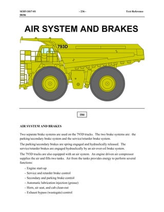
  • 1. 184 AIR SYSTEM AND BRAKES Two separate brake systems are used on the 793D trucks. The two brake systems are: the parking/secondary brake system and the service/retarder brake system. The parking/secondary brakes are spring engaged and hydraulically released. The service/retarder brakes are engaged hydraulically by an air-over-oil brake system. The 793D trucks are also equipped with an air system. An engine driven air compressor supplies the air and fills two tanks. Air from the tanks provides energy to perform several functions: - Engine start-up - Service and retarder brake control - Secondary and parking brake control - Automatic lubrication injection (grease) - Horn, air seat, and cab clean-out - Exhaust bypass (wastegate) control SERV1817-01 - 236 - Text Reference 08/06
  • 2. Shown is a cutaway illustration of an oil cooled brake assembly. The brakes are environmentally sealed and adjustment free. Oil continually flows through the brake discs for cooling. Duo-Cone seals prevent the cooling oil from leaking to the ground or transferring into the axle housing. The wheel bearing adjustment must be maintained to keep the Duo-Cone seals from leaking. The smaller piston (yellow) is used to ENGAGE the secondary and parking brakes. The parking brakes are spring ENGAGED and hydraulically RELEASED. The larger piston (purple) is used to ENGAGE the retarder/service brakes. The retarder/service brakes are engaged hydraulically by an air-over-oil brake system. 185 SERV1817-01 - 237 - Text Reference 08/06
  • 3. 186 Air Charging System This schematic shows the flow of air through the air charging system. Air flows from the air compressor, through the air dryer, to the service/retarder brake tank. Air from the service/retarder brake tank enters the pressure protection valve. When the pressure in the service/retarder tank reaches 550 kPa (80 psi), the pressure protection valve allows air to flow to the parking/secondary brake tank, the air start system, the engine wastegate valve, the automatic lubrication system, and the accessory circuits (horn, air seat, and cab clean-out). All tanks have a check valve at the air supply port to prevent a loss of air if a leak upstream of the tank occurs. SERV1817-01 - 238 - Text Reference 08/06
  • 4. The air system is charged by an air compressor mounted on the left front of the engine. To handle the increased air flow, a large air dryer is used, and the hoses and tubing have also been increased in size. System pressure is controlled by the governor (arrow). The governor maintains the system pressure between 660 and 830 kPa (95 and 120 psi). The governor setting can be adjusted with a screw below the cover on the governor. Turn the adjustment screw OUT to increase the pressure and IN to decrease the pressure. The air compressor is lubricated with engine oil and cooled with aftercooler coolant. To test the air compressor efficiency, lower the air system pressure to 480 kPa (70 psi). Start the engine and raise the engine speed to HIGH IDLE. When the air system pressure reaches 585 kPa (85 psi), measure the time that it takes to build system pressure from 585 kPa (85 psi) to 690 kPa (100 psi). The time to raise the pressure should be 50 seconds or less. If the time recorded is greater than 50 seconds, check for leaks or a restriction in the system. If no leaks or restrictions are found, the air compressor may have a problem. 187 SERV1817-01 - 239 - Text Reference 08/06
  • 5. Air flows from the air compressor to the air dryer (arrow) located in front of the left front tire. The air system can be charged from a remote air supply through a ground level connector inside the left frame. The air dryer removes contaminants and moisture from the air system. The condition of the desiccant in the air dryer should be checked every 250 hours and changed periodically (determined by the humidity of the local climate). When the air compressor governor senses that system air pressure is at the cut-out pressure of 830 kPa (120 psi), the governor sends an air pressure signal to the purge valve in the bottom of the dryers. The purge valve opens and air pressure that is trapped in the air dryer is exhausted through the desiccant, an oil filter, and the purge valve. An air system relief valve is located on the air dryers to protect the system if the air compressor governor malfunctions. A heating element in the bottom of the dryer prevents moisture in the dryer from freezing in cold weather. 188 SERV1817-01 - 240 - Text Reference 08/06
  • 6. Air flows through the air dryer and fills two tanks. The service/retarder brake tank (1) is located on the right platform. This tank also supplies air for the air start system. The second tank is located behind the cab and supplies air for the parking/secondary brake system. A relief valve (2) protects the air system when the air dryer has exhausted and the ball check valves in the air dryer outlet port closes. The check valves separate the air system from the air dryer relief valves. Condensation should be drained from the tank daily through the drain valve (3). 189 SERV1817-01 - 241 - Text Reference 08/06
  • 7. Located behind the operator’s station is a pressure protection valve (1). Supply air flows from the large service/retarder brake tank, through the pressure protection valve, to the secondary air system and accessories. The pressure protection valve opens at 550 kPa (80 psi) and closes at 482 kPa (70 psi). If the secondary air lines or an accessory circuit fails, the pressure protection valve maintains a minimum of 482 kPa (70 psi) in the service/retarder brake circuit. To test the pressure protection valve, drain the air pressure to approximately 345 kPa (50 psi). Use the VIMS display to observe the brake air pressure. With the engine running at LOW IDLE, press the horn button. Record the air pressure when the horn sounds. This pressure reading is the open setting of the pressure protection valve. Slowly drain the air pressure and record the air pressure when the horn turns off. This pressure reading is the setting of the pressure protection valve when it closes. The air system pressure sensor (2) provides an input signal to the Brake ECM. The Brake ECM sends a signal to the VIMS, which informs the operator if a problem exists in the air system. Also located behind the operator’s station are the service/retarder brake switch, the parking/secondary brake switch, and the brake light switch (see Visual No. 141). 190 SERV1817-01 - 242 - Text Reference 08/06
  • 8. Located behind the operator’s station is the parking/secondary brake air tank. A drain valve is located on the right side of the cab. Moisture should be drained from the tank daily through the drain valve (see Visual No. 32). A check valve (arrow) prevents a loss of air if an air line breaks upstream of the air tank. 191 SERV1817-01 - 243 - Text Reference 08/06
  • 9. 192 Brake Systems This schematic shows the flow of air through the service/retarder brake air system when the retarder (manual and automatic) is RELEASED, and the service brakes are ENGAGED. Supply air pressure flows from the large service brake air tank to the relay valves and the service brake valve and manual retarder valve. The manual retarder valve blocks the flow of air. The service brake valve allows air to flow to the double check valve that blocks the passage to the manual retarder. Air pressure from the service brake valve flows through the double check valve to the service brake relay valve. The service brake relay valve opens and metered air flows from the large service brake air tank to the brake cylinders. The relay valves reduce the time required to engage and release the brakes. Air from the service brake valve also flows to the brake light switch and the service/retarder switch. Depressing the service brake pedal turns ON the brake lights and changes the transmission shift points and anti-hunt timer. SERV1817-01 - 244 - Text Reference 08/06
  • 10. When the manual retarder lever is moved, air flows through the double check valve that blocks the passage to the service brake valve. Air pressure from the manual retarder brake valve flows through the double check valve to the service brake relay valve. Air from the manual retarder brake valve also flows to the retarder switch, the brake light switch and the service/retarder switch. Engaging the manual retarder turns ON the retarder dash lamp, the brake lights, and changes the transmission shift points and anti-hunt timer. SERV1817-01 - 245 - Text Reference 08/06
  • 11. 193 Shown is the parking/secondary brake hydraulic and air system with the secondary brakes RELEASED and the parking brakes ENGAGED. Supply air from the parking/secondary brake air tank flows to the secondary brake valve and is blocked from flowing to the inverter valve signal port. Supply air is allowed to flow through the inverter valve and is blocked by the parking brake air valve. No air pressure is present to move the spool in the parking brake release valve. Supply oil from the parking brake release pump is blocked by the spool. Oil from the parking brake is open to drain through the parking brake release valve, which allows the springs in the parking brake to ENGAGE the brakes. A parking/secondary brake switch is located in the air line between the parking brake valve and the parking brake release valve. The switch provides an input signal to the Transmission/Chassis ECM. When the parking or secondary brakes are ENGAGED, the switch signals the Transmission/Chassis ECM to allow rapid downshifts. SERV1817-01 - 246 - Text Reference 08/06
  • 12. The manual retarder valve (arrow) is controlled by the retarder lever in the cab. Normally, the retarder valve blocks air flow to the service brake relay valve near the brake master cylinders. When the retarder lever is pulled down, air flows to the service brake relay valve [maximum pressure is approximately 550 kPa (80 psi)]. The retarder lever is used to modulate the service brake engagement by metering the amount of air flow to the service brake relay valve. The retarder engages the same brakes as the service brake pedal (see Visual No. 43), but is easier to control for brake modulation. The retarder system allows the machine to maintain a constant speed on long downgrades. The retarder will not apply all of the normal braking capacity. NOTICE Do not use the retarder control as a parking brake or to stop the machine. 194 SERV1817-01 - 247 - Text Reference 08/06
  • 13. The service brake valve (1) is controlled by the brake pedal in the cab. Supply air for the service brake valve and the manual retarder valve is supplied from the manifold (3). When the service brakes are engaged, air flows from the service brake valve to the service brake relay valve near the brake master cylinders [maximum pressure is 825 kPa (120 psi)]. The service brake valve engages the same brakes as the retarder, but does not control brake modulation as precisely as the retarder. Air from the service brake valve and the manual retarder valve flows through the double check valve (4) to the service brake relay valve. If the manual retarder and the service brakes are engaged at the same time, air from the system with the highest pressure will flow through the double check valve to the service brake relay valve. Air from the manual retarder valve also flows through the retarder switch (5) to the double check valve (4). The retarder switch turns on the amber retarder lamp on the dash in the operator’s station when the manual retarder is ENGAGED. The brake light switch and the service/retarder brake switch (see Visual No. 141) are located in the supply line to the front brake oil cooler diverter valve (see Visual No. 211). The service brake valve, the manual retarder valve and the Automatic Retarder Control (ARC) valve send air to these switches when engaged. 195 SERV1817-01 - 248 - Text Reference 08/06
  • 14. The secondary brake valve (2) is controlled by the red pedal in the cab (see Visual No. 43). When the secondary brakes are engaged, air flows from the secondary brake valve to the signal port of an inverter valve (see next visual). The inverter valve then blocks the flow of air from the secondary brake tank to the brake release valve (see Visual No. 199). Blocking the air from the brake release valve positions the spool in the brake release valve to drain the oil from the parking brakes, which allows the springs in the parking brake to ENGAGE the brakes. The secondary brake valve can be used to modulate parking brake engagement by metering the amount of air flow to the brake release valve. The parking brake air valve (see Visual No. 44) on the shift console in the cab also controls the flow of air to the brake release valve, but the parking brake air valve does not modulate the parking brake application. The parking/secondary brake switch (see Visual No. 141) is located in the supply line to the brake release valve. The secondary brake valve and the parking brake air valve send air to this switch when engaged. INSTRUCTOR NOTE: The ARC system will be discussed in more detail later in this presentation. SERV1817-01 - 249 - Text Reference 08/06
  • 15. When the secondary brakes are engaged, air flows from the secondary brake valve to the signal port (1) of the inverter valve (2). The inverter valve then blocks the flow of air from the secondary brake tank to the brake release valve. Blocking the air from the brake release valve positions the spool in the brake release valve to drain the oil from the parking brakes, which allows the springs in the parking brake to ENGAGE the brakes. 196 SERV1817-01 - 250 - Text Reference 08/06
  • 16. Shown is the parking brake release pump (arrow). Oil flows from the brake release pump through the brake release filter to the brake release valve. 197 SERV1817-01 - 251 - Text Reference 08/06
  • 17. Oil flows from the parking brake release pump, through the parking brake release filter (1), to the parking brake release valve. An oil filter bypass switch (2) is located on the filter housing. The oil filter bypass switch provides an input signal to the Brake ECM. The Brake ECM sends the signal to the VIMS, which informs the operator if the filter is restricted. Also shown are the rear brake oil coolers (3). Oil flows from the rear brake cooling pump and the brake oil cooling filter from the hoist valve, through two screens and the two rear brake oil coolers to the rear brakes. 198 SERV1817-01 - 252 - Text Reference 08/06
  • 18. Oil from the parking brake release pump flows through the parking brake release filter to the brake release valve (1) located inside the right rear frame. Oil flows from the parking brake release valve to the parking brake piston in the brakes when the parking brakes are released. Supply air from the parking brake air valve in the cab or the secondary brake valve flows through the small hose (2) to an air chamber in the brake release valve. The brake release valve contains an air piston that moves a spool. The spool either directs oil to RELEASE the parking brakes or drains oil to ENGAGE the parking brakes. A relief valve (3) in the brake release valve limits the system pressure for releasing the brakes. The setting of the relief valve is 4700 ± 200 kPa (680 ± 30 psi). Supply oil flows from the brake release valve through an orifice and a screen (4) to the brake oil makeup tank. If the makeup tank is not receiving proper flow of oil, remove and check the orifice and screen (4) for plugging. To release the parking brakes for service work or towing, the electric motor that turns the towing pump (5) can be energized by the brake release switch located in the cab (see Visual No. 48). The pump sends oil to the brake release valve to RELEASE the parking brakes. Towing pump pressure is controlled by a relief valve in the towing pump. 199 SERV1817-01 - 253 - Text Reference 08/06
  • 19. 200 Normally, supply oil flows from the parking brake release pump, through the parking brake release filter, to the parking brake release valve. If air pressure is present from the parking brake air valve or the secondary brake valve, supply oil flows past the relief valve, the check valve, and the spool to RELEASE the parking brakes. The relief valve limits the system pressure for releasing the brakes and for the pilot oil to shift the hoist valve. The setting of the relief valve in the parking brake valve is 4700 ± 200 kPa (680 ± 30 psi). This schematic shows the flow of oil through the parking brake release system when the towing system is activated. Oil flow from the parking brake release pump has stopped. The towing motor is energized, and air pressure is present above the parking brake release valve piston. The air pressure moves the spool in the parking brake release valve down to block the drain port. Oil flows from the towing pump to the parking brake release valve and the parking brakes. The check valve to the right of the parking brake release filter blocks the oil from the towing pump from flowing to the parking brake release pump. SERV1817-01 - 254 - Text Reference 08/06
  • 20. During towing, the parking brake release pressure is limited by a relief valve in the towing pump. When the relief valve opens, oil transfers from the pressure side to the suction side of the towing pump. The setting of the relief valve is approximately 4480 kPa (650 psi). A check valve in the outlet port of the towing pump prevents oil from flowing to the towing pump during normal operation. To check the brake release system used for towing, connect a gauge to the parking brake release pressure tap on the rear axle (see Visual No. 204). Use a long gauge hose so the gauge can be held in the cab. With the parking brake air valve in the RELEASE position and the key start switch in the ON position, energize the parking brake release switch used for towing (on the dash). The parking brake release pressure should increase to 4480 kPa (650 psi). Turn off the switch when the pressure stops increasing. The parking brake release pressure must increase to a minimum of 3790 kPa (550 psi). The parking brakes start to release between 3100 and 3445 kPa (450 and 500 psi). During towing, the brake release switch on the dash must be energized whenever the parking brake release pressure decreases below this level or the brakes will drag. The parking brakes are fully released between 3445 and 3860 kPa (500 and 560 psi). NOTE: A minimum of 550 kPa (80 psi) air pressure must be available at the parking brake release valve to ensure full release of the brakes for towing. NOTICE Activate the brake release switch only when additional pressure is required to release the brakes. Leaving the brake release (towing) motor energized continuously will drain the batteries. The parking brake release pressure setting must not exceed 5445 kPa (790 psi). Exceeding this pressure can cause internal damage to the brake assembly. SERV1817-01 - 255 - Text Reference 08/06
  • 21. The front service brake relay valve (1) receives metered air from only the service brake valve or the manual retarder valve. When the service brakes or manual retarder brakes are ENGAGED, the front relay valve opens and metered air flows from the service brake reservoir to the four brake cylinders (2) (2 shown). The brake relay valves reduce the time required to engage and release the brakes. The brake cylinders operate by air-over-oil. When the metered air enters the brake cylinders, a piston moves down and pressurizes the oil in the bottom of the cylinders. Two brake cylinders supply oil to the front brakes and two brake cylinders supply oil to the rear brakes. 201 SERV1817-01 - 256 - Text Reference 08/06
  • 22. As the brake discs in the brake assemblies wear, more oil is needed from the brake cylinders to compensate for the wear. The makeup oil tank (1) supplies makeup oil for the brake cylinders. Oil from the parking brake release valve flows through an orifice and screen to provide a continuous supply of oil to the makeup tank. Low flow to the makeup tank can cause the makeup oil reserve to decrease and cause the brake cylinders to overstroke. To check for makeup oil flow, remove the cover from the makeup oil tank. With the engine at HIGH IDLE, a stream of oil filling the tank should be visible. If a stream of oil is not visible, there may be a restriction in the filter or hose to the tank or pump flow may be low. Keep the service brake ENGAGED for at least one minute. If air is in the system or a loss of oil downstream from the cylinders occurs, the piston in the cylinder will overstroke and cause an indicator rod to extend and open the brake overstroke switch (2). The switch provides an input signal to the Brake ECM. The Brake ECM sends the signal to the VIMS, which informs the operator of the condition of the service/retarder brake oil circuit. If an overstroke condition occurs, the problem must be repaired and the indicator rod pushed in to end the warning. 202 SERV1817-01 - 257 - Text Reference 08/06
  • 23. The oil-to-air ratio of the brake cylinder is approximately 6.6 to 1. To test the brake cylinder, install a gauge in the fitting on top of the brake cylinder and a gauge on the pressure tap on the slack adjuster. When the service brakes are ENGAGED, if the air pressure in the brake cylinder is 690 kPa (100 psi), the oil pressure measured at the slack adjuster should be approximately 4560 kPa (660 psi). When the brakes are RELEASED, both pressures should return to zero. Inspect the condition of the breather for the brake cylinders (see Visual No. 21). Oil should not leak from the breather. Oil leaking from the breather is an indication that the oil piston seals in a brake cylinder needs replacement. Air flow from the breather during a brake application is an indication that a brake cylinder air piston seal needs replacement. Shown is one of the four brake oil temperature sensors (3). Four brake oil temperature sensors, one for each brake, are located in the brake oil cooling tubes. The brake oil temperature sensors provide input signals to the VIMS, which keeps the operator informed of the brake cooling oil temperature. The most common cause of high brake cooling oil temperature is operating a truck in a gear that is too high for the grade and not maintaining sufficient engine speed. Engine speed should be kept at approximately 1900 rpm during long downhill hauls. Also, make sure the pistons in the slack adjuster are not stuck and retaining too much pressure on the brakes (see Visuals No. 204 and 205). SERV1817-01 - 258 - Text Reference 08/06
  • 24. 203 This visual shows a sectional view of the brake cylinder when the brakes are ENGAGED. Air pressure from the brake relay valve enters the air inlet. The air pressure moves the air piston and the attached rod closes the valve in the oil piston. When the valve in the oil piston is closed, the oil piston pressurizes the oil in the cylinder. The pressure oil flows to the slack adjuster. If air is in the system or a loss of oil downstream from the cylinders occurs, the piston in the cylinder will overstroke, which causes the indicator rod to extend and open the brake overstroke switch. If an overstroke condition occurs, the problem must be repaired and the indicator rod pushed in to end the warning. When the air pressure is removed from behind the air piston, the spring moves the air piston and the attached rod opens the valve in the oil piston. Any makeup oil that is needed flows into the passage at the top of the oil chamber, through the valve, and into the oil chamber at the right of the oil piston. SERV1817-01 - 259 - Text Reference 08/06
  • 25. The truck is equipped with two slack adjusters. One of the slack adjusters is for the front brakes and one is for the rear brakes. The slack adjuster (1) shown is for the rear brakes. The slack adjusters compensate for brake disc wear by allowing a small volume of oil to flow through the slack adjuster and remain between the slack adjuster and the brake piston under low pressure. The slack adjusters maintain a slight pressure on the brake piston at all times. Brake cooling oil pressure maintains a small clearance between the brake discs. The service brake oil pressure can be measured at the two taps (2) located on top of the slack adjusters. Air can be removed from the service brakes through the two remote bleed valves (3) (one shown). The parking brake release pressure can be measured at the two taps (4) (one shown) on the axle housing. NOTE: Air can be removed from the front service brakes through bleed valves located on each wheel. 204 SERV1817-01 - 260 - Text Reference 08/06
  • 26. 205 This visual shows sectional views of the slack adjuster when the brakes are RELEASED and ENGAGED. When the brakes are ENGAGED, oil from the brake cylinders enters the slack adjusters and the two large pistons move outward. Each large piston supplies oil to one wheel brake. The large pistons pressurize the oil to the service brake pistons and ENGAGE the brakes. Normally, the service brakes are FULLY ENGAGED before the large pistons in the slack adjusters reach the end of their stroke. As the brake discs wear, the service brake piston will travel farther to FULLY ENGAGE the brakes. When the service brake piston travels farther, the large piston in the slack adjuster moves farther out and contacts the end cover. The pressure in the slack adjuster increases until the small piston moves and allows makeup oil from the brake cylinders to flow to the service brake piston. When the brakes are RELEASED, the springs in the service brakes push the service brake pistons away from the brake discs. The oil from the service brake pistons pushes the large pistons in the slack adjuster to the center of the slack adjuster. Makeup oil that was used to ENGAGE the brakes is replenished at the brake cylinders from the makeup tank. SERV1817-01 - 261 - Text Reference 08/06
  • 27. The spring behind the large piston causes some oil pressure to be felt on the service brake piston when the brakes are RELEASED (residual pressure). Keeping some pressure on the brake piston provides rapid brake engagement with a minimum amount of brake cylinder piston travel. The slack adjusters can be checked for correct operation by opening the service brake bleed screw with the brakes RELEASED. A small amount of oil should flow from the bleed screw when the screw is opened. The small flow of oil verifies that the spring behind the large piston in the slack adjuster is maintaining some pressure on the service brake piston. Another check to verify correct slack adjuster operation is to connect a gauge to the pressure tap on top of the slack adjuster and another gauge at the service brake bleed screw location. With system air pressure at maximum and the service brake pedal depressed, the pressure reading on both gauges should be approximately the same. When the brakes are RELEASED, the pressure at the slack adjuster should return to zero. The pressure at the service brake bleed screw location should return to the residual pressure held on the brakes by the slack adjuster piston. The residual pressures at the service brake bleed screw location should be: Front: 59 kPa (8.6 psi) Rear: 68 kPa (9.9 psi) Low residual pressure may indicate a failed slack adjuster. High residual pressure may also indicate a failed slack adjuster or warped brake discs. To check for warped brake discs, rotate the wheel to see if the pressure fluctuates. If the pressure fluctuates while rotating the wheel, the brake discs are probably warped and should be replaced. To check for brake cooling oil leakage, block the brake cooling ports and pressurize each brake assembly to a maximum of 138 kPa (20 psi). Close off the air supply source and observe the pressure trapped in the brake assembly for five minutes. The trapped pressure should not decrease. SERV1817-01 - 262 - Text Reference 08/06