High-Quality Single-Shot Facial 3D Capture
•
2 likes•515 views

This document describes a passive stereo vision system that can capture the 3D geometry of a human face in a single shot with high quality. The system uses a calibration method with fiducial markers on a sphere to calibrate multiple cameras. It then performs stereo matching across camera pairs to generate a dense disparity map and 3D mesh for the face. The system introduces an image-based technique to refine the mesh and capture fine geometric details like pores. Evaluation shows the system can accurately capture faces of varying ages, genders and expressions using both a high-end studio setup and a consumer binocular camera.

Recommended
More Related Content
What's hot
What's hot (20)
Viewers also liked
Viewers also liked (12)
Similar to High-Quality Single-Shot Facial 3D Capture
Similar to High-Quality Single-Shot Facial 3D Capture (20)
Recently uploaded
Recently uploaded (20)
High-Quality Single-Shot Facial 3D Capture
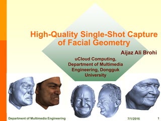
- 1. High-Quality Single-Shot Capture of Facial Geometry Aijaz Ali Brohi uCloud Computing, Department of Multimedia Engineering, Dongguk University 7/1/2016Department of Multimedia Engineering 1
- 2. Table of Contents •Abstract •Introduction •Related Work •Face Scanning •Refinement •Results •Discussion •Conclusion and Future Work 7/1/2016Department of Multimedia Engineering 2
- 3. Abstract •Passive Stereo System for capturing the 3D geometry of a face in a single-shot. – Under light source. – Low cast and easy to deploy. – Results are submillimeter accurate and commensurate. • State of the art systems based on active lighting • models meet the quality requirements of a demanding domain. – Recovered models are shown • High-end cameras in a studio setting. • A consumer binocular-stereo camera. • Scalability across a spectrum of camera. – Primary Technical Contribution • A modification of standard stereo refinement methods to capture pore-scale geometry. – Secondary Technical Contribution • A calibration method suited to face capture systems. 7/1/2016Department of Multimedia Engineering 3
- 4. Abstract •System Contribution – Includes multiple demonstrations of system robustness and quality. • Capture in a studio setup. • Capture off a consumer binocular-stereo camera. • Scanning of faces of varying gender and ethnicity and age. • Capture of highly-transient facial expression. • scanning a physical mask to provide ground-truth validation. • Figure 1: Left: Face model captured using a seven camera studio setup; • Center: capture systems; • Right: Face model captured using consumer binocular-stereo camera. 7/1/2016Department of Multimedia Engineering 4
- 5. Motivation •Why High Quality of Human Face Capturing and 3D Faces? – Interest of movie, cartoons, theaters, games, medical, , print media, and other industries. • More natural user interfaces and archival purposes. – A key application is the synthesis of a desired sequence of speech and facial expression under arbitrary lighting. – Reproducing realistic human faces is still a challenge for computer graphics. • because humans are sensitive to facial appearance and quickly sense any anomalies in 3D geometry or dynamics. 7/1/2016Department of Multimedia Engineering 5
- 6. Motivation •Paper Objectives – Concerned with the capture of 3D geometry of the face. – Active Systems • Based on laser, structured light or gradient based illumination. – Active lights brings robustness. – Effectively augments an object surface. • It requires special-purpose hardware and time-multiplexing. • Polarization-based methods – Constrain deployment to a single camera at a fixed viewpoint. – Passive Stereo Vision Systems • To be an extremely versatile modality for constructing 3D models. • It captures in a single shot, readily adapts to different arrangements and numbers of cameras. – No constraint on camera position. – Integrates 3D data captured over multiple distances and at different scales. – Captures texture with the recovered 3D data. – Uses commodity hardware. – Idea • Combine advantages of passive stereo system with high quality of active systems. 7/1/2016Department of Multimedia Engineering 6
- 7. Motivation •This paper presents a passive stereo vision system that computes the 3D geometry of the face. – Reliability and accuracy. – Introduces an image-based embossing technique to capture mesoscopic facial geometry. – Quality of synthesized faces from our system equals that achieved with gradient-based illumination. • Equal the performance of active systems. • Capture in a single shot under standard light sources. • Low-cost, and ease-of deployment. 7/1/2016Department of Multimedia Engineering 7
- 8. Related Work •Techniques for capturing geometry of a human face – Stereo capture of a face augmented with skin markings [Parke 1974]. – A hybrid system that combines a recovered depth map and recovered surface normals to generate a model [Nehab et al. 2005]. – A system for acquiring high-quality surface normals using polarized gradient- based illumination to generate high-resolution 3D reconstructions [Weyrich et al.2006], and in [Ma et al. 2007]. • A hybrid system of structured light and stereo [Weise et al. 2007]. • The application of the technique to facial expression transfer in [Weise et al. 2009]. •Recent work on single shot – Photometric stereo is described in [Hernandez et al. 2008]. – A hybrid system of active light and augmented skin markings for creating a photo real human face in [Alexander et al. 2009]. 7/1/2016Department of Multimedia Engineering 8
- 9. Related Work •This paper presents stereo matching and generation of a 3D Mesh. – Approach of refining recovered 3D data based on a data-driven – photo-consistency and surface-smoothing. – Commercial solutions [DI3D 2009] as well as concurrent work by [Bradley et al. 2010] are also applying MVS to the domain of face scanning. – Capture fine modulations of the geometry that are irrecoverable using stereo disparity alone. Shape recipes are instructive on the relationship between image data and shape data [Torralba and Freeman 2003]. – Fine-scale details are the mesh optimization in [Hiep et al. 2009]. – The modeling in [Golovinskiy et al. 2006; Bickel et al. 2008]. – Extraction of mesostructured from diffuse ambient occlusion [Bickel et al. 2007] or specularity in [Chen et al. 2006]. – This paper method is similar to [Glencross et al. 2008] which describes qualitative recovery of 3D information for bas-relief surfaces but the technical approaches are different. 7/1/2016Department of Multimedia Engineering 9
- 10. Contributions •The systemic contribution is to demonstrate a state-of-the-art passive stereo vision system for face scanning. •Past weaknesses have been overcome to yield a technology that is – Single-shot, low-cost, easy to deploy, and has impact in two areas. •Professional capture of high quality face models. – argue the passive stereo is on an equal footing with active systems. •The emerging area of consumer stereo photography – Face scanning can be accomplished using a consumer binocular-stereo camera. •Technical contributions • Modeling of mesoscopic geometry. • The calibration method. • Extensions to generic stereo refinement methods. • Tailor the processing to faces. 7/1/2016Department of Multimedia Engineering 10
- 11. Methodology and Proposed System 7/1/2016Department of Multimedia Engineering 11 The proposed system Steps of Processing
- 12. Face Scanning •Camera calibration is a pre-processing stage. •The run-time system begins with pairwise stereo matching. – Uses a pyramidal approach • Results at lower resolutions guide the matching at higher resolution. • Matches are computed at pixel level to give dense matches across the face. • The matches are used to generate a 3D mesh. •The mesh is refined using a modification of the traditional approach. – Photo-consistency and smoothing terms are augmented. 7/1/2016Department of Multimedia Engineering 12
- 13. Calibration •Achieving a straightforward and reliable calibration for a face-capture system. – Sphere augmented with fiducials. • Each fiducial is a double circle. • The center points of the circles provide the correspondences between cameras. • Providing a known metric distance DF that can be used to set scale. • Fiducials can be placed by hand with arbitrary distribution. • Fiducials were printed on sticky paper. 7/1/2016Department of Multimedia Engineering 13 Fiducials are placed randomly on the calibration sphere. A fiducial consists of two checkerboard circles with red dots at their centers. The fiducial defines a known distance DF .
- 14. Calibration •Advantages of Fiducial based Calibration – Well Suited place for camera and face capture. • A calibration sphere is approximately head-sized and placed at the intended position of the subject. • Sphere has no preferred direction in space. • This method requires only a small number of views and provides sub-pixel accurate features. • The calibration sphere occupies the same workspace as the subject’s head in the run-time system. – Calibration data is collected and well estimated. – Calibration is fully automatic. 7/1/2016Department of Multimedia Engineering 14
- 15. Image Preprocessing 12 bit Raw Format Image from cameras Converted to floating RGB Images Subsampled through Bayer-pattern ( de- Bayering using VNG [Chang et al. 1999] ) Mask generation using cues and color hue and saturation. Grayscale by retaining 7/1/2016Department of Multimedia Engineering 15
- 16. Pairwise Stereo-Reconstruction •Steps – First step is to rectify the images to obtain row-aligned epi-polar geometry. • Face Segmented out of the images using cues of background subtraction and skin color. – An image pyramid is generated for each rectified image by factor-of-two subsampling using Gaussian convolution. – Lowest-resolution layer of the pyramid is chosen to be around 150 150 pixels. – Matching is done pairwise between neighboring cameras and at pixel level to establish dense matches across the face. 7/1/2016Department of Multimedia Engineering 16
- 17. uniqueness constraint is Enforced. instantiation of refinement formulation performed. Pixels do not fulfill constraints are re- matched. Check smoothness, uniqueness and ordering constraints for each pixel Matches are computed for all pixels. 7/1/2016Department of Multimedia Engineering 17 Pairwise Stereo-Reconstruction •Matching starts at the lowest-resolution layer of the pyramid. •The resulting disparity map provides input to the next higher layer. •Where it is used to constrain the search area for matching. •Up to the highest-resolution layer of the pyramid 160px 160px 1280px 1280px
- 18. Pixel Matching •Block-matching algorithm using normalized cross-correlation (NCC). •Matching is performed along the epi-polar line only. – Pixel p in image I is matched against all pixels in image J. – The best match is retained. – Matching is performed twice per layer. – The initial matching • Computes putative matches for all pixels using the disparity estimates of the preceding layer to constrain the search area. – Next • Check for each pixel smoothness, uniqueness and ordering constraints. 7/1/2016Department of Multimedia Engineering 18
- 19. Constraints •The system can make use of constraints that hold for human faces. – Pixels in image I are matched against image J. – Vice-versa from image J to image I. – Acceptance of a match at pixel p in image I is subject to three constraints • Smoothness Constraint – computed disparity at p is consistent with neighbors in a surrounding window. • Uniqueness Constraint – The matching needs to be bijective » if p in image I matches to q in image J then q must also match to p. • Ordering Constraint – Computed disparity at p does not exceed the disparity of its right-neighbor pixel by more than one pixel. 7/1/2016Department of Multimedia Engineering 19
- 20. Meshing •Each camera-pair produces one disparity map – To compute a corresponding array of 3D points and a corresponding array of surface normals. – 3D points and surface normals are collected across all camera pairs. – Outliers are removed using a simplified approach of [Merrell et al. 2007]. – The resulting set of 3D points and normals is input to a Poisson surface reconstruction [Kazhdan et al. 2006]. – The output is a triangular mesh, each vertex consisting of a 3D point plus surface normal. 7/1/2016Department of Multimedia Engineering 20
- 21. Refinement •The refinement consists of a linear combination – Photometric consistency and surface consistency – The refinement is performed both on the disparity map and on the surface. 7/1/2016Department of Multimedia Engineering 21
- 22. Disparity Map Refinement •Sub-pixel disparity values are updated in every iteration as a linear combination of dp and ds, – Where dp is an adjustment in the direction of improved photometric consistency, and ds is an adjustment in the direction of improved surface consistency. – The refinement is terminated after a predefined number of iterations (40 for the lower-resolution layers and 180 for highest layer). • Results after computation of disparity photometric consistency and disparity surface refinement. • Convergence of the refinement over the first 1000 iterations at layer. The images in the back show samples of the surface at iterations 0,1,5,10,100 and 1000. 7/1/2016Department of Multimedia Engineering 22
- 23. Surface Refinement •The surface refinement differs from the disparity map refinement – To refine in continuous 3-space and provide smooth surface. – To keep computation tractable and restrict the refinement to along the normal direction (n) at (X). – To define a refinement resolution. – The normals are not changed during the refinement. – Computing updates for X as a linear combination of Xp and Xs, • Xp is an adjustment in the direction of improved photometric-consistency. • Xs is an adjustment in the direction of improved surface-consistency. 7/1/2016Department of Multimedia Engineering 23
- 24. Mesoscopic Augmentation •The refinement results in surface geometry – Smooth across skin pores and fine wrinkles. – The result is flatness and lack of realism in synthesized views of the face. – visual inspection shows the obvious presence of pores and fine wrinkles in the images. – This is due to the fact that light reflected by a diffuse surface is related to the integral of the incoming light. • pores, part of the incoming light is blocked and the point thus appears darker. – Method • augmenting the macroscopic geometry with fine scale features does produce a significant improvement in the perceived quality of reconstructed face geometry. 7/1/2016Department of Multimedia Engineering 24
- 25. Mesoscopic Augmentation •Mesoscopic augmentation – This figure shows part of a forehead on the left and a zoomed-in patch on the right. – Note that the mesoscopic augmentation adds high-frequency details such as pores, while coarser features, such as the spot showed on the right, usually do not influence the geometry, since they usually do not contain very high spatial frequencies. 7/1/2016Department of Multimedia Engineering 25
- 26. Results •Capture Process – Results were obtained using two capture systems • A studio setup and a consumer binocular-stereo camera. • Neighboring camera pairs subtend an angle of about 20 Degreeat the head and the outermost cameras subtend an angle of about 110 Degree. • There are two Canon 500D cameras on each side, and three Canon 5D cameras that are arranged in a triangle and dedicated to the frontal view of the face. – Use Darkened room for transient facial expression • All cameras to open their apertures for two seconds and triggering the external flash with a one second delay. – The compute time, from image input to output of a 3D model, takes around 20 minutes. • The stereo matching is pyramidal and it is straight forward to quickly generate models at the lower-resolution layers. 7/1/2016Department of Multimedia Engineering 26
- 27. Results •Quantitative Evaluation – Results for a physical mask of known ground truth. – The mask was created by taking a plaster-cast of a face, – Scanning with laser, – and printing on an Object Connex 500 3D printer. – Figure 9 shows the mask which is half a face. Error is measured as perpendicular distance between the registered ground-truth model and recovered model. • (a) Physical mask of known ground-truth; • (b) Recovered model color-coded by error; • (c) Distribution of the signed absolute error between the ground-truth and the registered recovered model. 7/1/2016Department of Multimedia Engineering 27
- 28. Results •Error statistics – Regions like the nostrils • Algorithm did not reconstruct because the nostril interior is invisible in the images. – The errors are an over-estimate in the sense. – Figure 10 provides a visual comparison of the ground-truth and recovered models. • Left: image of the physical mask; Center: rendering of the recovered model; Right: rendering of the physical mask. 7/1/2016Department of Multimedia Engineering 28
- 29. Results •Qualitative Evaluation – Figure 8 shows results for a variety of subjects of varying gender, ethnicity, age, and facial expression. – Figure 11 demonstrates high fidelity reconstruction for a subject with geometric variation in the skin at a range of scales. 7/1/2016Department of Multimedia Engineering 29 Recovered model for a face with geometric variation in the skin at a range of scales.
- 30. Results •Qualitative Evaluation – Figure 12 shows both the subtle deformations of mesoscopic detail in distorted areas as well as their consistency in regions that do not undergo deformation. Recovered models of a subject for two different expressions. 7/1/2016Department of Multimedia Engineering 30
- 31. Results •Qualitative Evaluation – Figure 13 shows results for a subject with dark-colored skin. – Figure 14 shows models recovered for highly-transient facial expression. • The subject slapped his own cheek causing a fast-moving shock-wave across the face. • Top : Images of a subject slapping himself and causing a shock-wave in the face. • Bottom : the respective reconstructions. 7/1/2016Department of Multimedia Engineering 31 Recovered model for a face with dark-colored skin.
- 32. Results •Qualitative Evaluation – Figure 15 shows results for capture from the Fuji camera. • Image capture with the Fuji under normal ambient light yielded very noisy images. – Capture with a bright diffuse light source solved this problem. – Left: Images from the Fuji binocular-stereo camera. – Center: the recovered model. Right: Close-up of a region around the eye. 7/1/2016Department of Multimedia Engineering 32
- 33. Discussion •Robustness – Two contrasting capture systems • Studio setup with seven prosumer SLR cameras plus indirect lighting. • A consumer binocular-stereo camera. • A spectrum ranging from – High-quality images to point-and-shoot. – Lower-quality images with lens distortion. • A Spectrum of varying camera configuration – All around front hemisphere of head to binocular stereo with a small baseline. • Good quality face models • Calibration method and run-time system are robust. – Camera configuration and image characteristics. •Current Limitations – Specularity on the face is a problem when capturing under direct lighting. • Tip of the nose reflects a bright light source. – Specular areas typically distort the mesh. – Ways to deal • Using indirect lighting or cross polarization. • Post processing to explicitly detect the affected area and create a plausible reconstruction. 7/1/2016Department of Multimedia Engineering 33
- 34. Conclusions and Future Work •To obtain high-quality face models use active light, and they offer reliability and accuracy. – Ability to produce point measurements of submillimeter accuracy. – Ability to accentuate detail and enhance recovery of fine-scale 3D geometry. •Passive stereo vision uses single-shot capture under standard light sources. •Faces provide the kind of dense evenly-distributed texture that is perfect for stereo matching and 3D reconstruction. •A state-of-the-art passive stereo system for face scanning. – It competes with active systems in reliability and quality for high-end applications. – Low Cost – Versatile enough to work off a consumer stereo camera. 7/1/2016Department of Multimedia Engineering 34
- 35. Conclusions and Future Work •Demonstration – An augmented type of stereo refinement to qualitatively recover pore-scale geometry. – Yield improved visual realism in synthesized faces. •Passive stereo has matured into a robust technology for capturing models of the face. 7/1/2016Department of Multimedia Engineering 35
- 36. 7/1/2016Department of Multimedia Engineering 36