Create room separations lines for the structure columns
•
0 likes•245 views

It’s very common situation in real life scenario when we receive a structure model from the engineers and the structure columns don’t “cut” the room areas...

Recommended
More Related Content
Similar to Create room separations lines for the structure columns
Similar to Create room separations lines for the structure columns (20)
More from Wojciech Klepacki
Recently uploaded
Recently uploaded (20)
Create room separations lines for the structure columns
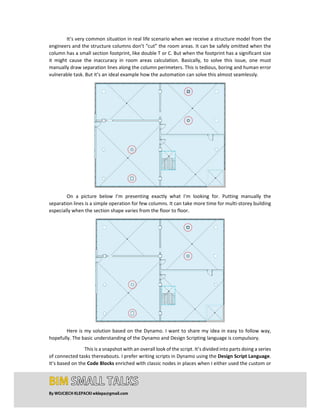
- 1. By WOJCIECH KLEPACKI wklepa@gmail.com It’s very common situation in real life scenario when we receive a structure model from the engineers and the structure columns don’t “cut” the room areas. It can be safely omitted when the column has a small section footprint, like double T or C. But when the footprint has a significant size it might cause the inaccuracy in room areas calculation. Basically, to solve this issue, one must manually draw separation lines along the column perimeters. This is tedious, boring and human error vulnerable task. But it’s an ideal example how the automation can solve this almost seamlessly. On a picture below I’m presenting exactly what I’m looking for. Putting manually the separation lines is a simple operation for few columns. It can take more time for multi‐storey building especially when the section shape varies from the floor to floor. Here is my solution based on the Dynamo. I want to share my idea in easy to follow way, hopefully. The basic understanding of the Dynamo and Design Scripting language is compulsory. This is a snapshot with an overall look of the script. It’s divided into parts doing a series of connected tasks thereabouts. I prefer writing scripts in Dynamo using the Design Script Language. It’s based on the Code Blocks enriched with classic nodes in places when I either used the custom or
- 2. By WOJCIECH KLEPACKI wklepa@gmail.com third‐party nodes or when I decided to leave them for code clarity. It’s a matter of a good practice to plug watch nodes to monitor the outcome in critical locations. The whole idea of this script is to keep the user inputs on the very low level, almost “zero‐ touch‐code”. The first part shown below selects the plans from the model. Subsequently, it extracts the associated levels from the plans. It gives only one unique plan per level as an output. This data is necessary to draw the room separation lines because this is the way how the RoomSeparator.FromCurve works. This node plays the crucial part in the workflow. In the beginning, I must collect all the views in the model: Then I’m cleaning the potential “nulls” in the view names. Subsequently, I’m splitting the view names to extract the real names.
- 3. By WOJCIECH KLEPACKI wklepa@gmail.com Now, I should consider only the views associated with the plans, filter the “empty” levels if any and group plans by the levels. I’m doing this because I want to use this information later to match with the levels associated with the structural columns. This is the outcome I’m looking for:
- 4. By WOJCIECH KLEPACKI wklepa@gmail.com For the second logical part of the script I want to collect all the structural columns, find their locations, detect the intersection between the column geometry and the sketch plane related to every level and finally generate the room separation lines. I’m starting from collecting all the elements from the category “Structural Columns”. If necessary, I can filter them by family type or another parameter later. Now, we are interested in gathering all the columns, hence the filtering is not required. Next, let’s use a very well‐known chunk of the code to group the columns by levels: Now, I’m using the instance parameter “Base Level” values to extract the information about the levels from the columns. I need to create a sketch plane; this step is compulsory because of the RoomSeparator.FromCurve utilises this data to create room separation lines. Finally, I’m bringing the columns geometry into Dynamo to intersect with a sketch plane. Because it performs better than the built‐in Surface.PerimeterCurves node, I’m using the Surfaces.DeconstructSurface node from LunchBox package. Please pay attention that it gives a series of surfaces as a resultant of the intersection.
- 5. By WOJCIECH KLEPACKI wklepa@gmail.com Subsequently. I’m matching the levels assigned to columns with the plans related to these same levels: The next part is little tricky to follow if you haven’t seen it before. Pay attention, that inside the code, there are pieces of script related to extracting the information from the particular level of the nested lists. Instead of using List.Map node I’m using “@‐2<1>” syntax in Code Block. This is basically equal to “Use Levels” procedure in a classic node: Once you get familiar with this, it becomes very easy to follow. The “@‐3<1>” will apply a function on the third level of the nested list accordingly. The code above performs the flatten of the nested list. This list is reversed on the sublevel because I need to consider only the external outline if column “walls” has thickness. The tricky piece
- 6. By WOJCIECH KLEPACKI wklepa@gmail.com performs the checking; if only one curve exists on a list take this curve (the column is solid and has the circular section) if four curves are on a list take them as they are (the column is solid and has a polygonal section). In case of more than four curves are on the list take exactly half of them (the other half is responsible for the inner thickness lines). This assumption is a limitation I put on a script (please refer to the comment at the end of this article). In case of dealing with a column with 8 – sides polygon footprint, this portion of code must be changed. cntIdx=lstCnt==1? 0: lstCnt==4? 3: (lstCnt/2)‐1; defRng=0..cntIdx; This bit of code counts the curves on the list. It’s necessary because I need to convert a circular footprint to the two arcs. The reason is the RoomSeparator.FromCurve accepts only lines and curves. Subsequently, I want to extract the centres of the columns and if columns have a circular footprint, the end point of the radiuses. Please, pay attention that these are not radiuses themselves, only the points on the perimeter of the circles. Once I have this information extracted, I need to calculate the real radiuses. I’m using the length of vector function to solve this. This vector spans between the centre point of the circle and the point on its perimeter. To divide a circle into two arcs, I have to split it into four points first. I’m using the 4 – sides rectangular polygon to get the points. I’m extracting these points from the sublevel of the list using the described “@‐level<1>” method. The first arc has points with indexes 0,1,2 for the start, middle and the end. The second arc has 2,3,0 accordingly. Both of the arcs represent the circular column. I put some comments on the Code Block to make it clearer. Please take your time to analyse the code.
- 7. By WOJCIECH KLEPACKI wklepa@gmail.com The Dynamo itself lacks abilities to “sew” more complex lists together. The built‐in nodes like List.ReplaceItemAtIndex or ReplaceByCondition failed to solve the issue, I decided to write a custom ZIP Lists node in Python. The goal was to replace the single curves with two arcs to compose a full circle. The outcome is shown below:
- 8. By WOJCIECH KLEPACKI wklepa@gmail.com This is what the Python script is doing in a background. Initially, my intention was to write a script using plain “for in” loop but I was advised on the Stack Overflow forum, that using “for in zip” function performs better. The last portion of the script utilises the RoomSeparator.FromCurve node from the Clockwork package. This node generates an error when the curve type is a circle. It must be replaced by the two arcs or polygon. Just one more thing must be done to make it work. Make sure that the Lacing is set to Longest. In case this node is fed with well‐prepared data it should give a positive outcome. The script does the brilliant job for some general cases however, there is always a room for improvements. One can be interested in adding a chunk of code to detect the overlapping room separation line for instance. The other thing worth to mention is that the script will work only for the general and most common column footprints. It will generate separation lines for circles, tubes, and 4 – sides rectangular and non‐rectangular polygons. It may fail for complex shapes composed of multiple arc segments or ellipses. I decided to consider these specific cases separately mainly because they are not very common. For the purpose of this exercise, I’m detecting the structure columns placed directly in a model. It’s not very complicated to rearrange the script to collect the elements from the linked models. I suggest using nodes from the outstanding BimorphNodes package for instance: