1. Multi-master RS485 network
This document briefly describes adaptation of RS485 based systems for multi-master
applications and indicates main features and advantages. In particular, the following modification relates
to Info panel for fire alarm applications. However, this solution is applicable for other kindred
systems too. This report doesn’t provide a thorough description of Master and Slave modules. It
concerns only multi-master aspects.
Necessity of multi-master systems
Some applications demand highly reliable and robust systems that continue to function when
separate crucial units fail. No single central device is allowed for such designs. Otherwise, the whole
system would stop its operation in case of failure of the central device. Therefore, two or more identical
devices with functionality of the central unit are imperative to duplicate each other. This approach leads
to redundancy, helps survive faults of the central devices and improves user interface to boot. At least
one central device must function correctly to maintain the entire network.
RS485 limitations for multi-master systems
RS485 networks are usually based on Master/Slave arrangement. As a rule, these systems consist
of one Master and multiple Slave devices. Master module (MM) acts as a central unit of the system and
initiates data transfer to and from Slave devices. Slave modules (M) are only able to respond to
commands from MM.
Normally, two Master modules can’t share common RS485 bus. Only one device can transmit
data at any time to avoid collisions between active transmitters. Collisions cause errors and aren’t
permissible. Thus, two or more Master modules may coexist if they communicate with Slave modules
alternatively, not simultaneously. In this way, only one Master module pursues communication with
Slave modules at any time and no collisions occur between different Master modules.
Some protocols imply transfer of tokens between Master modules for ring topologies. The
Master module, which currently possesses the token, is permitted to send commands to all Slave
modules. Other competitive Master modules are inactive and wait for token to resume data transfer.
Overview
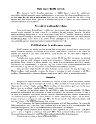
The proposed approach doesn’t transmit tokens between Master modules, which share common
RS485 bus. Figure 1 depicts placement of Master and Slave modules for multi-master applications.
There are shown four virtually identical Master modules for demonstration purposes on the image
below. However, an arbitrary number of Master modules is foreseen.
It’s necessary to set unique address for each MM to make them distinguishable. All Master
devices also need to know the total number of rivals in the network for successful operation. As soon as
an active MM completes data transfer, the next one starts communication with required Slave modules.
The protocol relies on expiration of silence intervals and doesn’t implicate any tokens. This fact doesn’t
increase overhead to comparison with single MM. All Master modules have identical priorities and,
thus, take control of the RS485 bus in equal time intervals.
It’s not mandatory for Master modules to communicate with all Slave modules. Each particular
MM communicates only with those Slave modules, which are mentioned in its configuration. That
enables to save precious time if Master Modules use a small part of Slave modules.
Multiple Master modules don’t influence or affect operation of Slave modules. Each Slave
device is able to respond to commands from every MM. When a Master module ceases to function,
others continue communication with I/O modules and detect fault of the defective device.
Of course, the operation of single MM isn’t forbidden.
2. Normally, operation of two or more Master deveices doesn’t encounter collisions. Nevertheless,
conflicts are unavoidable in some situations. Let’s assume that the RS485 bus breaks into two parts. In
this case, Master modules in each segment become active independently and perhaps simultaneously.
When the damaged cable restores, collisions are probable between active Master devices. If collisions
take place, Master modules immediately adjourn communication with I/O modules and wait for a certain
time to restart operation.
Fig. 1 Multi-master RS485 network
A large number of Master and Slave modules causes greater period between active states of the
Master modules. Each MM shows this period. Therefore, it’s easy to increase the baud rate for big
networks as much as necessary to adjust the total period.
Features
1) Arbitrary number of identical Master modules. The only difference is in the assigned unique
addresses. Dual port mode is allowed for one MM to create a closed loop (see Fig. 1).
2) All Master devices share common RS485 bus. Faulty devices don’t divide the RS485 bus apart.
3) Master devices exchange data only with necessary / configured Slave modules. That significantly
reduces poll time when a handful of I/O modules are used.
4) Each Slave module is available for any MM without exceptions.
5) Minor additional overhead to comparison with single MM. Each MM activates after expiration of
the specific silence interval in the RS485 bus.
6) Identical priorities for all Master devices. Each MM becomes active in equal time intervals.
7) Detection of defective Master devices
8) Master modules duplicate each other completely, if equal configuration is written to both devices. A
faulty MM doesn’t stop operation of the configured / selected I/O modules.
9) Operation without collisions