VIP Call Girls Service Kondapur Hyderabad Call +91-8250192130
ICT III - MPMC - Answer Key.pdf
1. DEPARTMENT OF ELECTRONICS AND COMMUNICATION ENGINEERING
INTENSIVE COACHING TEST
TEST- III – ANSWER KEY
EC 8691-MICROPROCESSORS AND MICROCONTROLLERS
PART A (10×02=20MARKS)
Sl.NO Questions
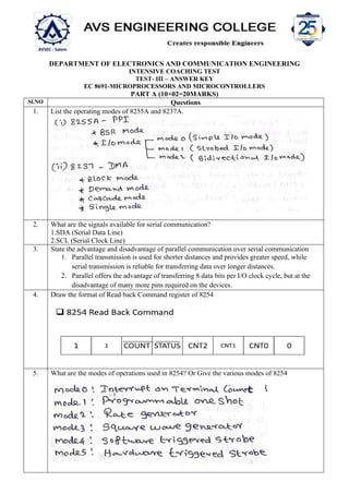
1. List the operating modes of 8255A and 8237A.
2. What are the signals available for serial communication?
1.SDA (Serial Data Line)
2.SCL (Serial Clock Line)
3. State the advantage and disadvantage of parallel communication over serial communication
1. Parallel transmission is used for shorter distances and provides greater speed, while
serial transmission is reliable for transferring data over longer distances.
2. Parallel offers the advantage of transferring 8 data bits per I/O clock cycle, but at the
disadvantage of many more pins required on the devices.
4. Draw the format of Read back Command register of 8254
5. What are the modes of operations used in 8254? Or Give the various modes of 8254
2. 6. Name the applications of programmable interval timer
7. What is the purpose of control word written to control register in 8255?
The control words written to control register state an I/O function for every I.O port. The bit
D7 of the control word verifies either the I/O function of the BSR function.
8. Write some examples of advanced processors
• 80186,80286,Pentium IV and Core2 duo
• I3,i5,i7.i9 and i11 processor
9. Show your understanding on bus request, bus Grant and cycle Stealing?
Collection of wires that carries data or address bit in it is termed as bus.
The DMA controller, after transferring one byte of data, releases control of the system buses
by
sending a bus grant signal through the control bus, lets the CPU process an instruction and
then requests access to the bus by sending the bus request signal through the control bus and
then transfers another byte of data
Cycle stealing is a method of accessing computer memory (RAM) or bus without interfering
3. with the CPU. It is similar to Direct memory access (DMA) for allowing I/O controllers to read
or write RAM without CPU intervention. Clever exploitation of specific CPU or bus timings
can
permit the CPU to run at full speed without any delay if external devices access memory not
actively participating in the CPU's current activity and complete the operations before any
possible CPU conflict. Such systems are nearly dual-port RAM without the expense of high
speed RAM. Most systems halt the CPU during the steal, essentially making it a form of DMA
by another name.
10. Draw the timing diagram of Interrupt acknowledgement on a minimum mode system.
4. PART B (5×13=65 MARKS)
11. a. Draw the block diagram of programmable Interrupt controller (8259) and explain its
operations (13)
5.
6. b. (i) Explain the operation of 8255 PPI Port A programmed as input and output in Mode 1
with necessary handshaking signals. (6)
(ii) Show and explain the ADC interfacing with 8086 microprocessors.
(7)
12. a. Explain the block diagram of 8255 PPI interface. (13)
7.
8. b. (i)Infer and explain the block diagram of ADC converter. (7)
(ii) How is A/D converter interfaced with 8086? (6)
13.` a. Explain in detail about DMA controller with its diagram. (13)
9. b. With functional block diagram, explain the operation and programming of 8251 USART
(Serial communication Interface) in detail (13)
10.
11.
12.
13. 14. a. (i) Design the block diagram of Polling method. (8)
1. Interrupts
Whenever any device need sits service, the device notifies the microcontroller by sending it an
interrupt signal. Up on receiving an interrupt signal, the microcontroller interrupts whatever it
is doing and serves the device.The program which is associated with the interrupt is called the
interrupt service routine(ISR)or interrupt handler.
2.Polling
The microcontroller continuously monitors the status of a given device. When the conditions
met, it performs the service. After that, it moves on to monitor the next device until everyone
is serviced.
14. (ii) Compare closely coupled configuration with loosely coupled configuration. (5)
TIGHTLY COUPLED LOOSELY COUPLED
(1) Tightly-coupled multiprocessor systems
contain multiple CPUs that are connected
at the bus level. These CPUs may have
access
to a central shared memory (SMP or UMA),
or
may participate in a memory hierarchy with
both local and shared memory (NUMA).
(1) Loosely-coupled multiprocessor system
(often referred to as clusters) are baesd on
multiple standalone single or dual processor
commodity computers interconnected via a
high speed communication system .
(2) Tightly-coupled systems perform better
&
are physically smaller than loosely-coupled
system.
(2) Loosely coupled system is just
Opposite of tightly coupled system.
(3) More expensive. (3) Less expensive.
15. (4) In a tightly-coupled system, the
delay Experienced , when a message is sent
from one computer to another is short, and
data
rate is high; that is, the number of bits per
second that can be transferred is large.
(4) In a loosely-coupled system, the opposite
is true: The inter-machine message delay is
large and the data rate is low.
(5) For example, two CPU chips on the same
printed circuit board and connected by wires
etched onto the board are likely to be tightly
Coupled.
(5) For example, two computers connected
by
a 2400 bit/sec modem over the telephone
system are certain to be loosely coupled.
(6) Tightly-coupled systems tend to be much
more energy efficient than clusters. This is
because considerable economies can be
realized by designing components to work
together from the beginning in tightly-
coupled
systems.
(6) loosely-coupled systems use components
that were not necessarily intended
specifically
for use in such systems.
b. Paraphrase the hardware enhancements of 80186, 80286 and Pentium
microprocessors compared to 8086. (13)
15 a. Explain the following
(i) Multiprocessor system (4)
(ii) Coprocessor (3)
(iii) Multiprogramming (3)
(iv) Semaphore (3)
(i) Multiprocessor system (4)
Multiprocessor Systems refer to the use of multiple processors that execute instructions
simultaneously and communicate using mailboxes and semaphores Maximum mode of
8086 is designed to implement 3 basic multiprocessor
configurations:
1. Coprocessor (8087)2. Closely coupled (dedicated I/O processor: 8089)
3. Loosely coupled (Multi bus)
Coprocessors and closely coupled configurations are similar - both the CPU and the
external processor share:
Memory
I/O system
Bus & bus control logic
Clock generator
(ii) Coprocessor (4)
Coprocessor Configuration:
WAIT instruction allows the processor to synchronize itself with external hardware, eg.,
waiting for 8087 math co-processor.
When the CPU executes WAIT waiting state.
TEST input is asserted (low), the waiting state is completed and execution will resume. ESC
instruction:
ESC opcode, operand, opcode: immediate value recognizable to a coprocessor as an
instruction opcode
16. Operand: name of a register or a memory address (in any mode)
When the CPU executes the ESC instruction, the processor accesses the memory operand by
placing the address on the address bus.
If a coprocessor is configured to share the system bus, it will recognize the ESC instruction
and therefore will get the opcode and the operand
(iii) Multiprogramming (4)
17. Semaphore was proposed by Dijkstra in 1965 which is a very significant
technique to manage concurrent processes by using a simple integer value,
which is known as a semaphore. Semaphore is simply an integer variable that
is shared between threads. This variable is used to solve the critical section
problem and to achieve process synchronization in the multiprocessing
environment.
Semaphores are of two types:
1. Binary Semaphore –
This is also known as mutex lock. It can have only two values – 0
and 1. Its value is initialized to 1. It is used to implement the solution
of critical section problems with multiple processes.
2. Counting Semaphore –
Its value can range over an unrestricted domain. It is used to control
access to a resource that has multiple instances
b. (i) Sketch the synchronous diagram between 8086 and its Coprocessor. (6)
(ii) Show how the inter-processor communication through shared memory. (7)
16 a. (i) Discuss how to interface an LCD display with 8086 microprocessors. (7)
(ii) Write a program to display the character “HELP US” for every 5 seconds using LCD
display. (8)
OR
b. Discuss in detail about loosely coupled configuration and explain the various schemes used
to solve the bus arbitration problem in multiprocessors (15)
Loosely Coupled Configuration:
- It has shared system bus, system memory, and system I/O
- each processor has its own clock as well as its own memory (in addition to access to the
system
resources, such as the system clock)
- clocks are of similar frequency, but asynchro-nous towards each other
- Used for medium to large multiprocessor systems
- Each module is capable of being the bus master
- Any module could be a processor capable of being a bus master, a coprocessor configuration
or a
closely coupled configuration.
- No direct connections between the modules. Each share the system bus and communicate
through
shared resources.
- Processor in their saeparate modules can simulateneously access their private subsystems
through
their local busses, and perorm their local data references and instruction fetches
independandtly. This
results in improved degree of concurrent processing.
- Ecellent for real time applications, as separate modules can be assigned specialized tasks.
ADVANTAGES:
- high system throughput can be achieved by having more than one CPU.
- The system can be expanded in modular form. Each bus master module is an independant
unit and
normally resides on a separate PC board. One can be added or removed without affecting the
others in
the system.
- A failure in one module normally does not affect the breakdown of the entire system and the
faulty
module can be easily detected and replaced
18. - each bus master has its own local bus to access dedicated memory or IO devices so a greater
de- gree
of parallel processing can be achieved.
PROBLEMS:
- Bus Arbitration (contention): Make sure that only 1 processor can access the bus at any given
time
- must synchronize local and system clocks for synchronous transfer
- requires control chips to tie into the system bus
Processor Bus Access:
- Needs some kind of priority allocation
- Output a Bus Request >BRQ= to request the bus >> BRQ line goes to some controller
- Input a Bus Grant >BGR= to gain access to bus >> BGR line from some controller
- Output a Bus Busy >BBSY= signal to hold the bus
Clocking:
- take both clocks and derive a common clock (ie: local clock & system clock)
or
- take leading edge of one of the clocks >> can alternate or change for each individual
operation
(clock will jitter)
Simultaneous bus requests are resolved on a priority basis: There are three schemes for
establishing priority:
1. Daisy chaining.
2. Polling.
3. Independent requesting
Daisy Chaining:
- Need a bus controller to monitor bus busy and bus request signals
- Sends a bus grant to a Master >> each Master either keeps the service or passes it on
- Controller synchronizes the clocks
- Master releases the Bus Busy signal when finished
Polling:
- Controller sends address of device to grant bus access
- Can use priority resolution here:
memory= highest priority
- Highest priority is granted first, if it does not respond, then a lower priority is granted, and so
on
until someone accepts
(ie: one request line, 3-bit grant line)
19. Independent:
- Each master has a request and grant line
- Now just a question of priority
- Could have fixed priority, rotating priority, etc.
usually fixed because memory is desired to be the highest priority
- Synchronization of the clocks must be performed once a Master is recognized
- Master will receive a common clock from one side and pass it to the controller which will
derive a
clock for transfer
- Can accurately predict calculations (since memory is always the highest priority)
R- Remembering, U- Understanding, Ap- Applying, A- Analyzing, E- Evaluating, C- Creating
FACULTY INCHARGE HOD PRINCIPAL