SlideShare a Scribd company logo
1 of 19
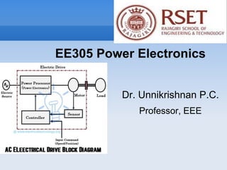
Dr. Unnikrishnan P.C.
Professor, EEE
EE305 Power Electronics
3-phase Half-wave controlled rectifier with R load
• is measured from the
point of natural
commutation
•The only difference of this circuit is that the outgoing
Thyristor keeps conducting till the incoming thyristor is
triggered.
•Each device conducts for 120
•Each phase supplies power for 120.
•A positive voltage across the blocking thyristor is possible.
•Continuous output voltage(0<α<30°)
•Discontinuous output voltage (30°<α<150°)
3-phase Half-wave controlled rectifier with R load
Three Phase Fully Controlled Bridge Converter
with R Load
•T1, T3, T5 : Common
Cathode Configuration
•T2, T4, T6 : Common
Anode Configuration
•If all are diodes,
changeover takes place
at X,Y,Z and P,Q,R
•T5 T1 takes place at X
•T6 T2 takes place at P
 = 30
Three Phase Fully Controlled Bridge Converter
with R-L-E Load
For any current to flow in the load at least
one device from the top group (T1, T3, T5)
and one from the bottom group (T2, T4,
T6) must conduct.
Thyristors are fired in the sequence
T1 → T2 → T3 → T4 → T5 → T6 → T1 with
60° interval between each firing.
Thyristors on the same phase leg are fired at an interval of 180° and
hence can not conduct simultaneously.
This leaves only six possible conduction mode for the converter in the
continuous conduction mode T1T2, T2T3, T3T4
, T4T5, T5T6, T6T1.
Three Phase Fully Controlled Bridge
Converter with R Load ( = 0)
Three Phase Fully Controlled Bridge Converter
with R Load
• =0 is equivalent to an uncontrolled full
wave bridge
•Thyristors should be fired at X,Y Z and
P,Q,R
•Each device conducts for 120
•Each phase supplies power for 240 in a
cycle provided load current is continuous.
•6 Pulses per Cycle, each of 60 .
•At any time only two phase supply power
to the load and one phase is open.
Three Phase Fully Controlled Bridge
Converter with R Load ( = 30)
Three Phase Fully Controlled Bridge
Converter with R Load ( = 60)
Three Phase Fully Controlled Bridge
Converter with R Load ( = 60)
For what firing angle,, the current through the load
becomes discontinuous ?
For =0 Vo varies from 1.5 V to 1.732 Volts
For =30 Vo varies from 0.866 V to 1.732 Volts
For =60 Vo varies from 0 V to 1.5 Volts
At =60, Vo touches the X-axis, so as the load current.
So beyond =60 load current becomes discontinuous.
Three Phase Fully Controlled Bridge
Converter with R Load ( = 90)
Three Phase Fully Controlled Bridge
Converter with R Load ( = 90)
For =90 Average value of the output voltage,Vo ,=0 but
the current is continuous. When is this possible?
This is possible only if the load is purely inductive. (The
average value of the voltage across an inductor is 0).
For other loads a continuous conduction is not possible for
=90.
Three Phase Fully Controlled Bridge
Converter with R Load ( = 120)
Three Phase Fully Controlled Bridge
Converter with R Load ( = 150)
Converter & Inverter
Converter Operation
For =0 Vo varies from 1.5 V to 1.732 Volts
For =30 Vo varies from 0.866 V to 1.732 Volts
For =60 Vo varies from 0 V to 1.5 Volts
For =90 Vo varies from -0.866 V to 0.866 Volts
Inverter Operation
For =120 Vo varies from -0.866 V to -1.5 Volts
For =150 Vo varies from -0.866 V to -1.732 Volts
Question
A DC motor (R-L-E Load) speed need to be controlled
using a single phase fully controlled converter. What
should be the values of  at starting and later to increase
speed?
The natural answer is =90 and then keep on
decreasing.
At =90, the instantaneous value of the input is maximum
and if this is applied to the armature, a very high current
will pass through the armature and damage.
So the safe value of  is around =150and reduce it
slowly
Comparison of various converters
The filter requirement reduces with increase in number of pulses
per cycle.
ee305-pe-m3-l2-over.pptx

More Related Content

Similar to ee305-pe-m3-l2-over.pptx

AC to ac Converters.pptx
AC to ac Converters.pptxAC to ac Converters.pptx
AC to ac Converters.pptx
MahmoudMustafa84
 
1 ph topic 8 resistors and inductors in series
1 ph topic 8 resistors and inductors in series1 ph topic 8 resistors and inductors in series
1 ph topic 8 resistors and inductors in series
mattnlis
 
lecture_7_ujt_and_put.pptx
lecture_7_ujt_and_put.pptxlecture_7_ujt_and_put.pptx
lecture_7_ujt_and_put.pptx
alfian454609
 
lecture_11_invertershhhhjjjjjjj*hbbbnnnnn
lecture_11_invertershhhhjjjjjjj*hbbbnnnnnlecture_11_invertershhhhjjjjjjj*hbbbnnnnn
lecture_11_invertershhhhjjjjjjj*hbbbnnnnn
ManhHoangVan
 

Similar to ee305-pe-m3-l2-over.pptx (20)

RGPV EX7102 UNITIII
RGPV EX7102 UNITIIIRGPV EX7102 UNITIII
RGPV EX7102 UNITIII
 
AC-AC voltage covertors (Cycloconvertors)
AC-AC voltage covertors (Cycloconvertors)AC-AC voltage covertors (Cycloconvertors)
AC-AC voltage covertors (Cycloconvertors)
 
Unit-5 AC-AC Cycloconverter
Unit-5 AC-AC CycloconverterUnit-5 AC-AC Cycloconverter
Unit-5 AC-AC Cycloconverter
 
Inverters (DC-AC)
Inverters (DC-AC)Inverters (DC-AC)
Inverters (DC-AC)
 
Multilevel Inverters [Autosaved].pptx
Multilevel Inverters [Autosaved].pptxMultilevel Inverters [Autosaved].pptx
Multilevel Inverters [Autosaved].pptx
 
AC to ac Converters.pptx
AC to ac Converters.pptxAC to ac Converters.pptx
AC to ac Converters.pptx
 
1 ph topic 8 resistors and inductors in series
1 ph topic 8 resistors and inductors in series1 ph topic 8 resistors and inductors in series
1 ph topic 8 resistors and inductors in series
 
unit4.pdf
unit4.pdfunit4.pdf
unit4.pdf
 
Thyristor_Converters.ppt
Thyristor_Converters.pptThyristor_Converters.ppt
Thyristor_Converters.ppt
 
Inverter PPT.ppt
Inverter PPT.pptInverter PPT.ppt
Inverter PPT.ppt
 
Power electronics Phase Controlled Rectifiers - SCR
Power electronics   Phase Controlled Rectifiers - SCRPower electronics   Phase Controlled Rectifiers - SCR
Power electronics Phase Controlled Rectifiers - SCR
 
lecture_7_ujt_and_put.pptx
lecture_7_ujt_and_put.pptxlecture_7_ujt_and_put.pptx
lecture_7_ujt_and_put.pptx
 
Inverter
InverterInverter
Inverter
 
555 timer
555 timer 555 timer
555 timer
 
A presentation on inverter by manoj
A presentation on inverter by manojA presentation on inverter by manoj
A presentation on inverter by manoj
 
Unit-2 AC-DC converter
Unit-2 AC-DC converter Unit-2 AC-DC converter
Unit-2 AC-DC converter
 
Bjt oscillators
Bjt oscillatorsBjt oscillators
Bjt oscillators
 
lecture_11_invertershhhhjjjjjjj*hbbbnnnnn
lecture_11_invertershhhhjjjjjjj*hbbbnnnnnlecture_11_invertershhhhjjjjjjj*hbbbnnnnn
lecture_11_invertershhhhjjjjjjj*hbbbnnnnn
 
Unit 1
Unit 1Unit 1
Unit 1
 
Rectifiers (ac dc)
Rectifiers (ac dc) Rectifiers (ac dc)
Rectifiers (ac dc)
 

Recently uploaded

Maher Othman Interior Design Portfolio..
Maher Othman Interior Design Portfolio..Maher Othman Interior Design Portfolio..
Maher Othman Interior Design Portfolio..
MaherOthman7
 
Final DBMS Manual (2).pdf final lab manual
Final DBMS Manual (2).pdf final lab manualFinal DBMS Manual (2).pdf final lab manual
Final DBMS Manual (2).pdf final lab manual
BalamuruganV28
 
Online crime reporting system project.pdf
Online crime reporting system project.pdfOnline crime reporting system project.pdf
Online crime reporting system project.pdf
Kamal Acharya
 
Tembisa Central Terminating Pills +27838792658 PHOMOLONG Top Abortion Pills F...
Tembisa Central Terminating Pills +27838792658 PHOMOLONG Top Abortion Pills F...Tembisa Central Terminating Pills +27838792658 PHOMOLONG Top Abortion Pills F...
Tembisa Central Terminating Pills +27838792658 PHOMOLONG Top Abortion Pills F...
drjose256
 
Microkernel in Operating System | Operating System
Microkernel in Operating System | Operating SystemMicrokernel in Operating System | Operating System
Microkernel in Operating System | Operating System
Sampad Kar
 

Recently uploaded (20)

BORESCOPE INSPECTION for engins CFM56.pdf
BORESCOPE INSPECTION for engins CFM56.pdfBORESCOPE INSPECTION for engins CFM56.pdf
BORESCOPE INSPECTION for engins CFM56.pdf
 
Geometric constructions Engineering Drawing.pdf
Geometric constructions Engineering Drawing.pdfGeometric constructions Engineering Drawing.pdf
Geometric constructions Engineering Drawing.pdf
 
Raashid final report on Embedded Systems
Raashid final report on Embedded SystemsRaashid final report on Embedded Systems
Raashid final report on Embedded Systems
 
Maher Othman Interior Design Portfolio..
Maher Othman Interior Design Portfolio..Maher Othman Interior Design Portfolio..
Maher Othman Interior Design Portfolio..
 
Final DBMS Manual (2).pdf final lab manual
Final DBMS Manual (2).pdf final lab manualFinal DBMS Manual (2).pdf final lab manual
Final DBMS Manual (2).pdf final lab manual
 
Piping and instrumentation diagram p.pdf
Piping and instrumentation diagram p.pdfPiping and instrumentation diagram p.pdf
Piping and instrumentation diagram p.pdf
 
Online crime reporting system project.pdf
Online crime reporting system project.pdfOnline crime reporting system project.pdf
Online crime reporting system project.pdf
 
Seismic Hazard Assessment Software in Python by Prof. Dr. Costas Sachpazis
Seismic Hazard Assessment Software in Python by Prof. Dr. Costas SachpazisSeismic Hazard Assessment Software in Python by Prof. Dr. Costas Sachpazis
Seismic Hazard Assessment Software in Python by Prof. Dr. Costas Sachpazis
 
Electrostatic field in a coaxial transmission line
Electrostatic field in a coaxial transmission lineElectrostatic field in a coaxial transmission line
Electrostatic field in a coaxial transmission line
 
Module-III Varried Flow.pptx GVF Definition, Water Surface Profile Dynamic Eq...
Module-III Varried Flow.pptx GVF Definition, Water Surface Profile Dynamic Eq...Module-III Varried Flow.pptx GVF Definition, Water Surface Profile Dynamic Eq...
Module-III Varried Flow.pptx GVF Definition, Water Surface Profile Dynamic Eq...
 
Research Methodolgy & Intellectual Property Rights Series 1
Research Methodolgy & Intellectual Property Rights Series 1Research Methodolgy & Intellectual Property Rights Series 1
Research Methodolgy & Intellectual Property Rights Series 1
 
AI in Healthcare Innovative use cases and applications.pdf
AI in Healthcare Innovative use cases and applications.pdfAI in Healthcare Innovative use cases and applications.pdf
AI in Healthcare Innovative use cases and applications.pdf
 
NEWLETTER FRANCE HELICES/ SDS SURFACE DRIVES - MAY 2024
NEWLETTER FRANCE HELICES/ SDS SURFACE DRIVES - MAY 2024NEWLETTER FRANCE HELICES/ SDS SURFACE DRIVES - MAY 2024
NEWLETTER FRANCE HELICES/ SDS SURFACE DRIVES - MAY 2024
 
litvinenko_Henry_Intrusion_Hong-Kong_2024.pdf
litvinenko_Henry_Intrusion_Hong-Kong_2024.pdflitvinenko_Henry_Intrusion_Hong-Kong_2024.pdf
litvinenko_Henry_Intrusion_Hong-Kong_2024.pdf
 
The battle for RAG, explore the pros and cons of using KnowledgeGraphs and Ve...
The battle for RAG, explore the pros and cons of using KnowledgeGraphs and Ve...The battle for RAG, explore the pros and cons of using KnowledgeGraphs and Ve...
The battle for RAG, explore the pros and cons of using KnowledgeGraphs and Ve...
 
Tembisa Central Terminating Pills +27838792658 PHOMOLONG Top Abortion Pills F...
Tembisa Central Terminating Pills +27838792658 PHOMOLONG Top Abortion Pills F...Tembisa Central Terminating Pills +27838792658 PHOMOLONG Top Abortion Pills F...
Tembisa Central Terminating Pills +27838792658 PHOMOLONG Top Abortion Pills F...
 
5G and 6G refer to generations of mobile network technology, each representin...
5G and 6G refer to generations of mobile network technology, each representin...5G and 6G refer to generations of mobile network technology, each representin...
5G and 6G refer to generations of mobile network technology, each representin...
 
Theory for How to calculation capacitor bank
Theory for How to calculation capacitor bankTheory for How to calculation capacitor bank
Theory for How to calculation capacitor bank
 
Low rpm Generator for efficient energy harnessing from a two stage wind turbine
Low rpm Generator for efficient energy harnessing from a two stage wind turbineLow rpm Generator for efficient energy harnessing from a two stage wind turbine
Low rpm Generator for efficient energy harnessing from a two stage wind turbine
 
Microkernel in Operating System | Operating System
Microkernel in Operating System | Operating SystemMicrokernel in Operating System | Operating System
Microkernel in Operating System | Operating System
 

ee305-pe-m3-l2-over.pptx

  • 1. Dr. Unnikrishnan P.C. Professor, EEE EE305 Power Electronics
  • 2. 3-phase Half-wave controlled rectifier with R load • is measured from the point of natural commutation
  • 3. •The only difference of this circuit is that the outgoing Thyristor keeps conducting till the incoming thyristor is triggered. •Each device conducts for 120 •Each phase supplies power for 120. •A positive voltage across the blocking thyristor is possible. •Continuous output voltage(0<α<30°) •Discontinuous output voltage (30°<α<150°) 3-phase Half-wave controlled rectifier with R load
  • 4. Three Phase Fully Controlled Bridge Converter with R Load •T1, T3, T5 : Common Cathode Configuration •T2, T4, T6 : Common Anode Configuration •If all are diodes, changeover takes place at X,Y,Z and P,Q,R •T5 T1 takes place at X •T6 T2 takes place at P
  • 6. Three Phase Fully Controlled Bridge Converter with R-L-E Load For any current to flow in the load at least one device from the top group (T1, T3, T5) and one from the bottom group (T2, T4, T6) must conduct. Thyristors are fired in the sequence T1 → T2 → T3 → T4 → T5 → T6 → T1 with 60° interval between each firing. Thyristors on the same phase leg are fired at an interval of 180° and hence can not conduct simultaneously. This leaves only six possible conduction mode for the converter in the continuous conduction mode T1T2, T2T3, T3T4 , T4T5, T5T6, T6T1.
  • 7. Three Phase Fully Controlled Bridge Converter with R Load ( = 0)
  • 8. Three Phase Fully Controlled Bridge Converter with R Load • =0 is equivalent to an uncontrolled full wave bridge •Thyristors should be fired at X,Y Z and P,Q,R •Each device conducts for 120 •Each phase supplies power for 240 in a cycle provided load current is continuous. •6 Pulses per Cycle, each of 60 . •At any time only two phase supply power to the load and one phase is open.
  • 9. Three Phase Fully Controlled Bridge Converter with R Load ( = 30)
  • 10. Three Phase Fully Controlled Bridge Converter with R Load ( = 60)
  • 11. Three Phase Fully Controlled Bridge Converter with R Load ( = 60) For what firing angle,, the current through the load becomes discontinuous ? For =0 Vo varies from 1.5 V to 1.732 Volts For =30 Vo varies from 0.866 V to 1.732 Volts For =60 Vo varies from 0 V to 1.5 Volts At =60, Vo touches the X-axis, so as the load current. So beyond =60 load current becomes discontinuous.
  • 12. Three Phase Fully Controlled Bridge Converter with R Load ( = 90)
  • 13. Three Phase Fully Controlled Bridge Converter with R Load ( = 90) For =90 Average value of the output voltage,Vo ,=0 but the current is continuous. When is this possible? This is possible only if the load is purely inductive. (The average value of the voltage across an inductor is 0). For other loads a continuous conduction is not possible for =90.
  • 14. Three Phase Fully Controlled Bridge Converter with R Load ( = 120)
  • 15. Three Phase Fully Controlled Bridge Converter with R Load ( = 150)
  • 16. Converter & Inverter Converter Operation For =0 Vo varies from 1.5 V to 1.732 Volts For =30 Vo varies from 0.866 V to 1.732 Volts For =60 Vo varies from 0 V to 1.5 Volts For =90 Vo varies from -0.866 V to 0.866 Volts Inverter Operation For =120 Vo varies from -0.866 V to -1.5 Volts For =150 Vo varies from -0.866 V to -1.732 Volts
  • 17. Question A DC motor (R-L-E Load) speed need to be controlled using a single phase fully controlled converter. What should be the values of  at starting and later to increase speed? The natural answer is =90 and then keep on decreasing. At =90, the instantaneous value of the input is maximum and if this is applied to the armature, a very high current will pass through the armature and damage. So the safe value of  is around =150and reduce it slowly
  • 18. Comparison of various converters The filter requirement reduces with increase in number of pulses per cycle.