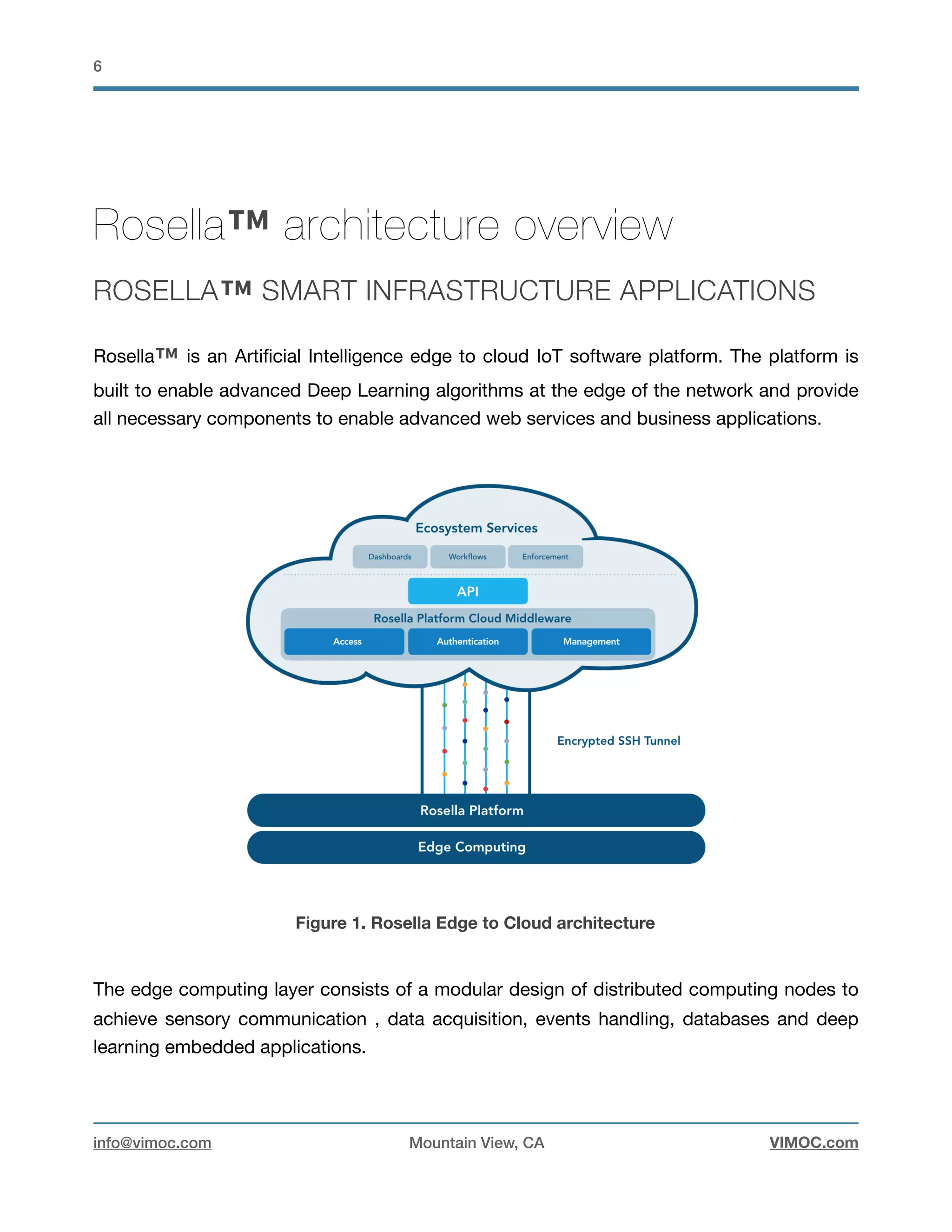
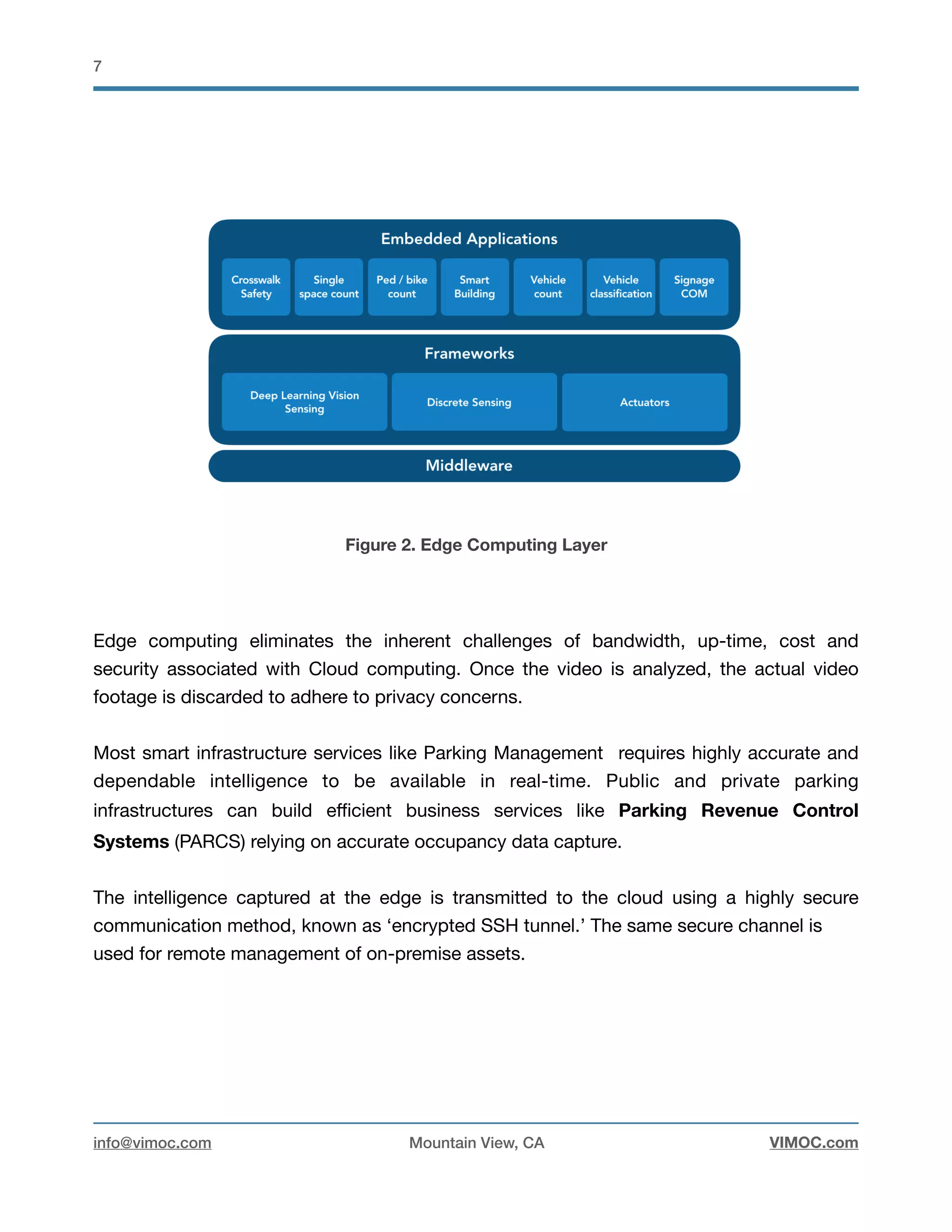
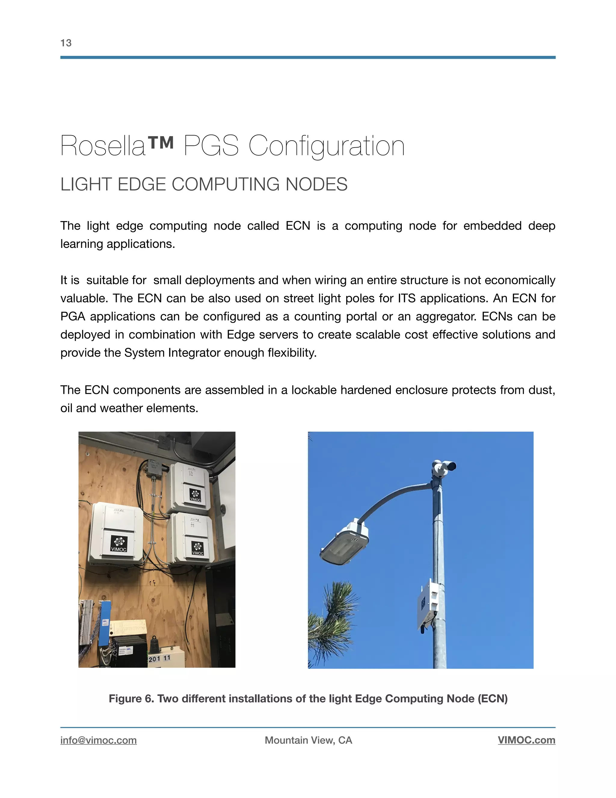
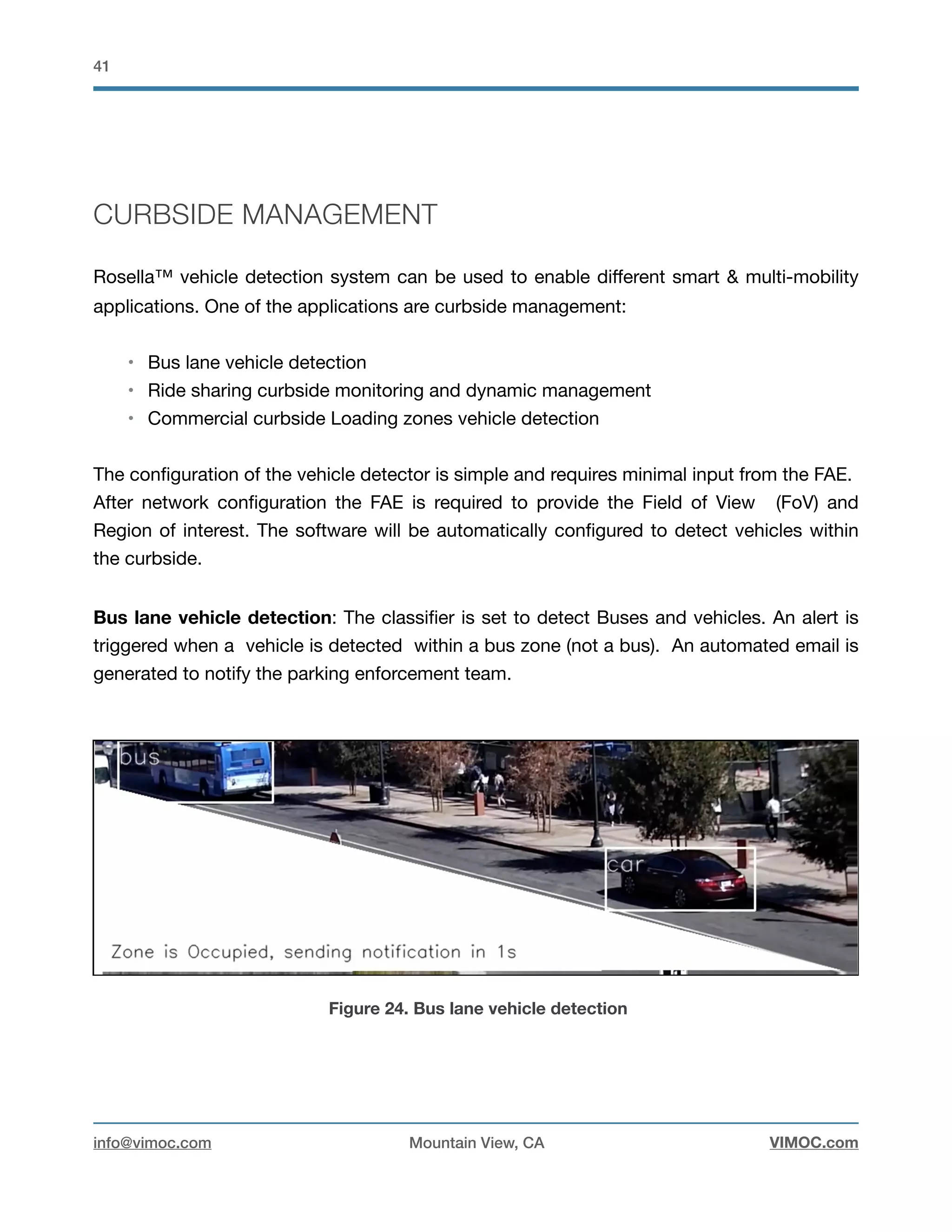
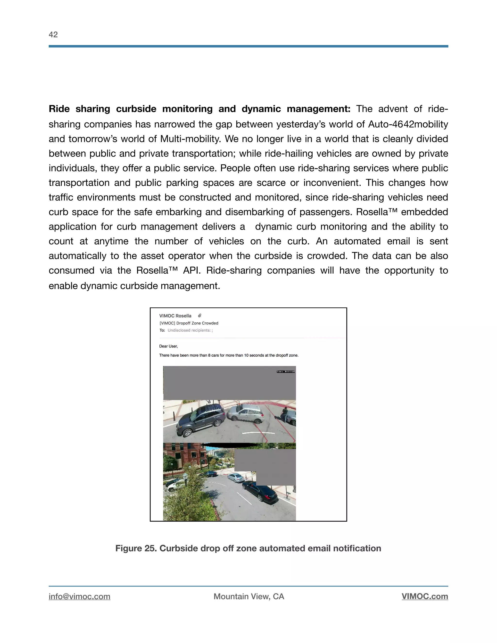
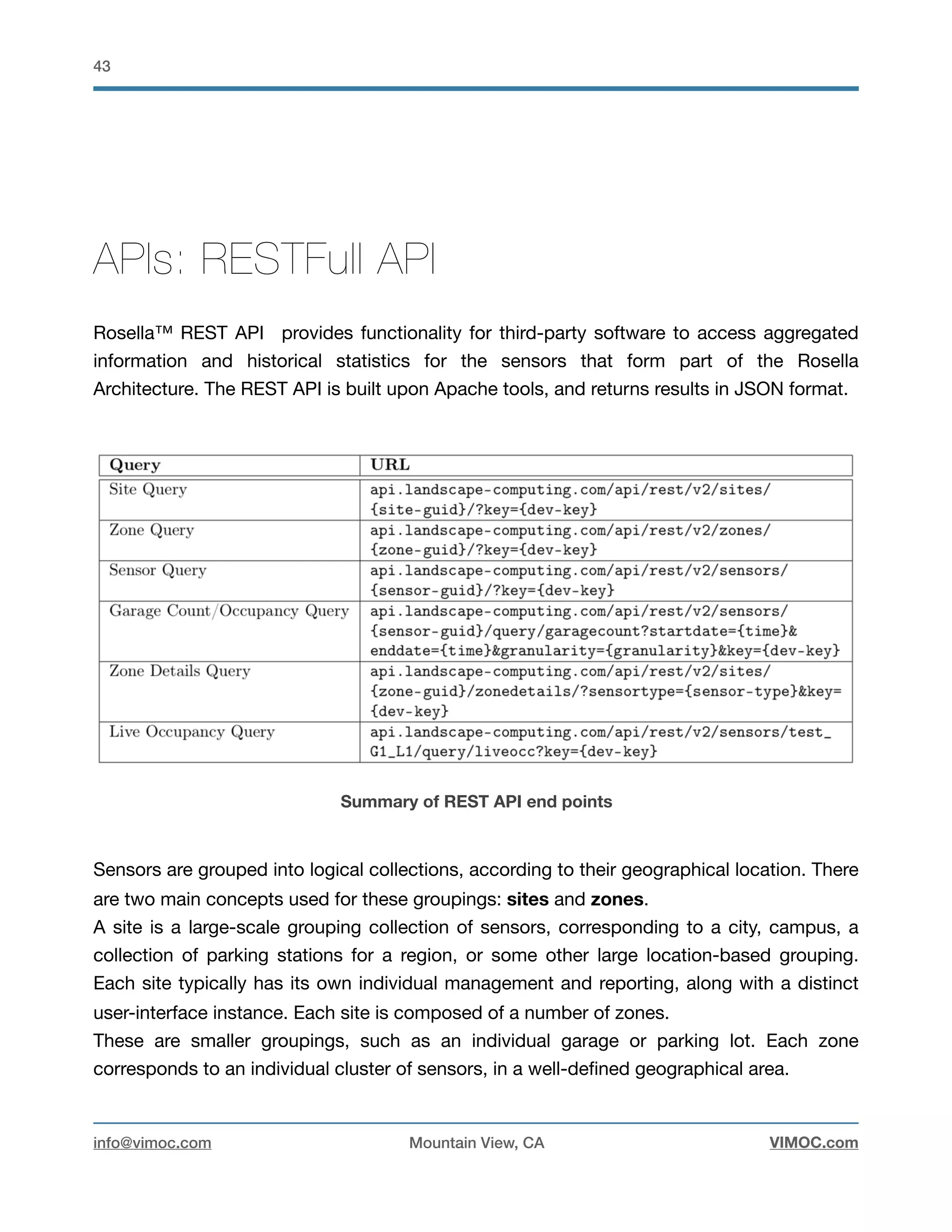
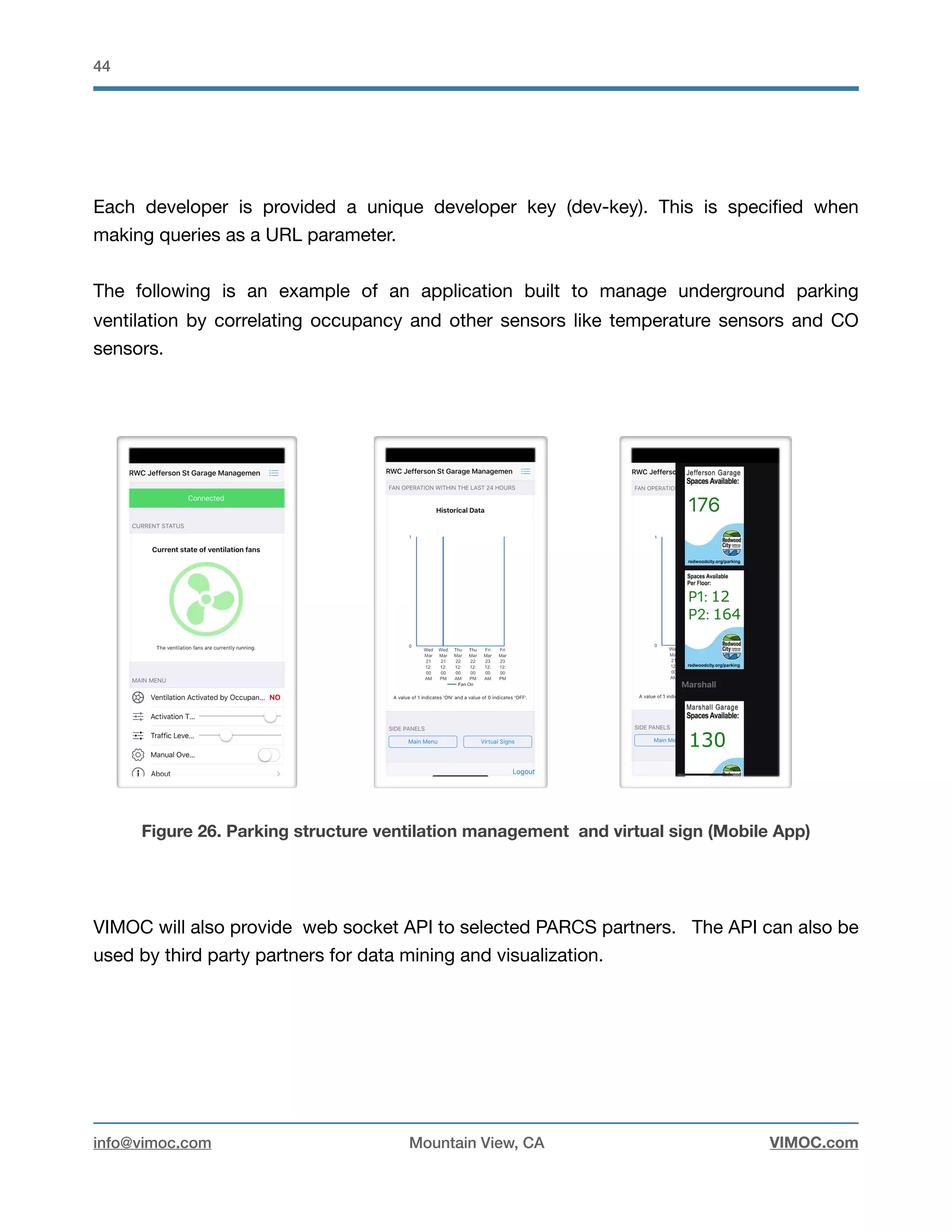
I am pleased to release the first version of the Rosella Reference Design Architecture and Applications document outlining requirements necessary to address the deployment of Rosella edge computing smart infrastructure platform with focus on the Parking Guidance Application (PGA)
2. !2
INTRODUCTION 4
Solution Overview 4
Rethinking Smart Infrastructure 4
applications 5
ROSELLA™ ARCHITECTURE OVERVIEW 6
Rosella™ Smart infraStructure APPLICATIONS 6
Rosella Overview 9
Rosella™ Best Practice for smart infrastructure applications 9
ROSELLA™ PGS CONFIGURATION 13
Light Edge Computing Nodes 13
Parking Structure Example 16
Occupancy Aggregator 18
Parking garage Configuration 18
Single space monitoring 25
Signage support 29
Crosswalk safety Pedestrian 30
CONSOLIDATING RESOURCES & ASSETS 32
Security and surveillance-CCTV 32
anpr Access control (oem only) 32
OTHER ROSELLA™ EMBEDDED APPLICATIONS 34
Multimodal traffic data capture 35
Pedestrian detection & Counting 38
Pedestrian detection: Safety 39
Vehicle/bicycle detection and counting 39
Curbside management 41
info@vimoc.com Mountain View, CA VIMOC.com
3. !3
APIS: RESTFULL API 43
PROJECT DESIGN ASSISTANCE 45
VIMOC CONTACT INFORMATION 45
LEGAL INFORMATION 45
info@vimoc.com Mountain View, CA VIMOC.com
4. !4
Introduction
SOLUTION OVERVIEW
This Reference Design Architecture and Applications document outlines requirements
necessary to address the deployment of Rosella™ edge computing smart infrastructure
platform with focus on the Parking Guidance Application (PGA). It also addresses best
practices in implementing a reliable and affordable design architecture to achieve long-term
performance.
RETHINKING SMART INFRASTRUCTURE
Mobility today is not always safe and secure, clean and sustainable, or inclusive and
efficient. For many, getting around is a daily struggle that consumes a significant portion of
their time, finances or both. Whether navigating a congested urban environment, finding a
parking space, picking up a customer or determining when an essential package will arrive,
the existing transport and mobility system can seem as much a hindrance as help.
Smarter Mobility is an important element within any modern smart infrastructure, it
enables us to get more from existing assets. It does this by improving our understanding of
the way our assets are performing, enabling better decisions over how we design, operate
and maintain them.
Parking Garages offer urban environments a way to direct vehicles to a dedicated structure,
resulting in a reduction of on-street congestion as drivers often precariously look for spaces
close to their destinations. Garages form an integral part of cleaner and more pleasant
urban spaces. The biggest hurdle to direct drivers to parking garages is the perceived risk
of entering a full garage without the guarantee of a quick exit.
info@vimoc.com Mountain View, CA VIMOC.com
5. !5
Real estate developers, asset owners and parking management operators are rapidly
deploying new technologies in both hardware and application software, providing useful
features and benefits to traditional and nontraditional customers.
VIMOC Rosella™ software platform supports the widest choice in networked hardware
devices, with system components such as edge computing nodes, edge servers, digital
cameras, sensors and networking equipments. A key element of deploying Rosella™
system is a reliable and flexible networking topology. The end result is the enablement of
Smarter Multi-Mobility solution to improve the efficiency and ease of an urban structure.
For parking structures general occupancy status, single space monitoring (especially for
high value spaces such as EV, ADA, visitor, carpool), automated parking structure
ventilation control, curbside management and crosswalk safety can be mixed and matched
in a flexible and dynamic system.
Today asset owners and operators are no longer bound to a limited and low performance
PGA solution because VIMOC provides true smart infrastructure enablement, allowing IT
and asset managers to reduce costs and leverage unlimited options to manage the long-
term sustainability of the infrastructure.
APPLICATIONS
VIMOC provides an end to end smart infrastructure solution with smart mobility and PGA
as core applications. Scaling in capacity and performance, Rosella™ is designed to enable
a highly reliable applications with the capability to enable other solutions by fusing other
sources of sensory data.
info@vimoc.com Mountain View, CA VIMOC.com
6. !6
Rosella™ architecture overview
ROSELLA™ SMART INFRASTRUCTURE APPLICATIONS
Rosella™ is an Artificial Intelligence edge to cloud IoT software platform. The platform is
built to enable advanced Deep Learning algorithms at the edge of the network and provide
all necessary components to enable advanced web services and business applications.
Figure 1. Rosella Edge to Cloud architecture
The edge computing layer consists of a modular design of distributed computing nodes to
achieve sensory communication , data acquisition, events handling, databases and deep
learning embedded applications.
info@vimoc.com Mountain View, CA VIMOC.com
7. !7
Figure 2. Edge Computing Layer
Edge computing eliminates the inherent challenges of bandwidth, up-time, cost and
security associated with Cloud computing. Once the video is analyzed, the actual video
footage is discarded to adhere to privacy concerns.
Most smart infrastructure services like Parking Management requires highly accurate and
dependable intelligence to be available in real-time. Public and private parking
infrastructures can build efficient business services like Parking Revenue Control
Systems (PARCS) relying on accurate occupancy data capture.
The intelligence captured at the edge is transmitted to the cloud using a highly secure
communication method, known as ‘encrypted SSH tunnel.’ The same secure channel is
used for remote management of on-premise assets.
info@vimoc.com Mountain View, CA VIMOC.com
8. !8
* Extended application to smart office/Lab. Industrial smart object detection and classification
** Part of SaaS licensing agreement for Express and Enterprise
*** Sensors: Imaging sensors and discrete sensors
Table 1. Rosella™ features and enabled applications
Rosella Features Rosella Express Rosella Enterprise Rosella Corporate
Rudi HW node (Tx1/Tx2) ✔ ✔ ✔
Edge Fog Computing Server ✖ ✔ ✔
Signage Support ✔ ✔ ✔
Signage Configuration ✖ ✔ ✔
CrossWalk Safety ✖ ✔ ✔
Single Space Detection/Count ✖ ✔ ✔
Ped/Bike Count ✖ ✔ ✔
Smart Building/Space * ✖ ✖ ✔
Vehicle Counting (Parking
occupancy)
✔ ✔ ✔
Vehicle Counting( Intelligent
Transportation)
✖ ✔ ✔
Vehicle Classification ✖ ✖ ✔
RestFull API ✔ ✔ ✔
Websocket API ✖ ✖ ✔
Smart Parking garage Ventilation ✖ ✔ ✔
License Plate Recognition ✖ ✖ Q3 2018
Data storage & retention ** 1 year 1 year UNLIMITED
Curb management ✖ ✖ ✔
Device management
Multilevel/Nested Parking
Structure
✖ ✔ ✔
Number of sensors *** 5-20 20-150 UNLIMITED
info@vimoc.com Mountain View, CA VIMOC.com
9. !9
ROSELLA OVERVIEW
This reference document is applicable to all Rosella™ platform applications. Rosella™
Corporate is a powerful AI-IoT management software designed for large-scale
deployments. Its a single-seat management capability enabling efficient administration
across sensors, light edge computing nodes and edge servers, regardless of total system
size or multiple-site distribution.
For systems demanding business efficiency, business awareness and precise/efficient
response to system failure, Rosella™ Corporate features interactive tools linked to
automated maintenance messaging. Rosella™ Corporate provides the ultimate system
reliability for smart infrastructure installations and services. Distributed Edge Computing,
combined with failover computing and redundant management edge nodes and edge
servers, ensure processing and services are never interrupted.
ROSELLA™ BEST PRACTICE FOR SMART
INFRASTRUCTURE APPLICATIONS
VIMOC recommends utilizing specific edge computing hardware devices for Rosella™
Edge. Edge applications are achieved by implementing advanced Deep Learning algorithm
on Edge computing devices. Two type of HW Edge Computing Devices are recommended:
1. Light-Computing Node: For Rosella™ express, Rosella™ Enterprise and
Rosella™ Corporate. Rudi from Connect tech inc. Pre-integrated with the
NVIDIA® Jetson™ TX2/TX1 supercomputer-on-module, providing 256 CUDA®
cores on the NVIDIA Maxwell™ or Pascal™ architectures. The system has 4GB
LPDDR4 memory, 4K video decode/ encode, WiFi, Bluetooth, USB 3.0, CAN
2.0b, USB 2.0, and mSATA and miniPCIe expansion. Multiple mounting options
available.
info@vimoc.com Mountain View, CA VIMOC.com
10. !10
2. Edge Server : For Rosella™ Enterprise and Corporate. HPE Edgeline EL4000
Converged Edge System accommodating multiple NVIDIA GPU cards. Up to four
independent server cartridges, including the HPE m510 servers, giving a 64 Intel
Xeon cores, 512 GB memory, 8 TB of SSDs, and 8 10GbE ports in a slim 1U
form factor. It can accommodate NVIDIA Tesla P4 cards 5 each connecting to
one server cartridge,
Figure 3. Light-Computing-Node Based on Rudi from Connect Tech Inc
Figure 4. Edge server based on HPE EdgeLine EL4000
info@vimoc.com Mountain View, CA VIMOC.com
11. !11
Rosella™ is available in two physical node types: light node and edge server node.
Together with Rosella™ embedded, the Rosella™ distributed system meets evolving
computing demand for new applications and performance requirements by easily adding
capacity and performance through the addition of GPU compute capability within the edge
server or in some situation the addition of light edge computing nodes. A single light
computing node connects to a maximum of 10 imaging sensors. A maximum 80 imaging
sensors are supported by an edge server node.
When computing nodes are idle (Example: No activity) in some areas they can be used to
compute busy computing tasks in other areas. This feature will allow a scalable and
efficient architecture.
VIMOC pioneered the implementation of embedded deep learning applications for smart
infrastructure and has implemented an end to end software solution with an automatic
management policy that requires minimal maintenance.
Sensors and actuators are important components within Rosella™ architecture. VIMOC
recommends the following devices:
1. Imaging Sensors: Rosella™ supports a range of IP cameras from major
manufacturers.
• Pelco: With recommended model IBE129-1R
• Axis: With recommended model P3225-LVE Mk II
• CISCO: With recommended model 3630 IP camera
2. Discrete Sensors: VIMOC support different type of communication protocols for
low power sensor deployments. Lora, Xbee, BLE, Wifi
3. Crosswalk Safety Actuators: from xwalk: (http://www.xwalk.com/)
info@vimoc.com Mountain View, CA VIMOC.com
12. !12
4. Signage: VIMOC supports two type of signs for PGA, an Edge to Edge high
resolution LED sign from Media Resources and a low resolution sign from
Daktronics.
5. Networking switch: CISCO WS-C2960X-48TS-LL CATALYST 2960X-48TS-LL
MANAGED SWITCH - 48 ETHERNET PORTS & 2 GIGABIT SFP PORTS.
Figure 5. Hardware/Networking topology
Network bandwidth is available using a high-performance setup. The 2960-X Series are
stackable Gigabit Ethernet Layer 2 and Layer 3 access switches. They’re easy to deploy,
manage, and troubleshoot. They offer automated software installation and port
configuration. And they help cut costs with energy-efficient features.
info@vimoc.com Mountain View, CA VIMOC.com
13. !13
Rosella™ PGS Configuration
LIGHT EDGE COMPUTING NODES
The light edge computing node called ECN is a computing node for embedded deep
learning applications.
It is suitable for small deployments and when wiring an entire structure is not economically
valuable. The ECN can be also used on street light poles for ITS applications. An ECN for
PGA applications can be configured as a counting portal or an aggregator. ECNs can be
deployed in combination with Edge servers to create scalable cost effective solutions and
provide the System Integrator enough flexibility.
The ECN components are assembled in a lockable hardened enclosure protects from dust,
oil and weather elements.
Figure 6. Two different installations of the light Edge Computing Node (ECN)
info@vimoc.com Mountain View, CA VIMOC.com
14. !14
Figure 7 illustrates an ECN high level electrical design. The main computing element is the
NVIDIA® Jetson™ TX2/TX1 supercomputer-on-module, providing 256 CUDA® cores on the
NVIDIA Maxwell™ or Pascal™ architectures. VIMOC supports different design topologies
using Rudi edge device from Connect Tech Inc. Figure 8, 9 demonstrates a design topology
for ECN using Rudi .
Figure 7. ECN configuration within NEMA box
info@vimoc.com Mountain View, CA VIMOC.com
15. !15
Figure 8. NEMA box ECN hardware configuration
Figure 9. NEMA box ECN hardware configuration. (1) Simple Supports remote reset
(2) Supports Ethernet WAN (3) Supports Cellular Failover (4) Smallish Enclosure (5) Does not
require additional power supply
info@vimoc.com Mountain View, CA VIMOC.com
16. !16
PARKING STRUCTURE EXAMPLE
Figure 10. Simple configuration example: wiring, Edge Computing Nodes (ECNs) location &
imaging sensors.
The occupancy system consists of 4 elements: (1) Counting portal (2) Aggregator (3)
signage (4) Imaging sensors. Figure 10 describes a simple installation diagram with 3
counting portals. Each counting portal in this example can perform Inbound and Outbound
vehicle traffic count. A counting portal ECN can have an aggregator role in the same time.
info@vimoc.com Mountain View, CA VIMOC.com
17. !17
The aggregator role is to aggregate data from each counter to calculate occupancy, another
important role is to provide the communication layer with third party signage devices.
Figure 11. Simple configuration example with each counting :
info@vimoc.com Mountain View, CA VIMOC.com
18. !18
OCCUPANCY AGGREGATOR
The aggregator is an edge software component that fuses together the information
provided by the various portal counters in order to keep track of the current occupancy of
the various garage areas and the total garage occupancy. The aggregator configurations file
is created based on the Parking structure, Capacity Table (CT) and the Edge Computing
Device/Camera Table (ECCT). Setting up the aggregator requires installation of
dependencies, compiling the aggregator code on the edge (Pre-installed) as well as
correctly configuring the aggregator config such that it matches the formal garage
definition. The System Integrator (SI) role is to capture the right information that will lead to
a correct configuration file. The VIMOC field engineers will assist VARs and SIs in achieving
this task.
PARKING GARAGE CONFIGURATION
The Capacity Table (CT) has two columns: Garage Area and Capacity. Garage areas are
typically but not necessarily levels of the garage. Each entry in the CT contains a unique
identifier of the garage area and the capacity of that area. Any alphanumerical name may be
assigned to the garage areas.
Below is an example of a Capacity Table for a garage with three levels and their respective
capacity.
Garage Area Capacity
Leve 3 50
Level 2 200
Level 1 100
info@vimoc.com Mountain View, CA VIMOC.com
19. !19
CT Constraint. The software currently assumes that cars can only move between areas
that are adjacent in the CT, in other words each garage area entry needs to be physically
adjacent to its neighboring entries. This often implies that the first CT entry has to be the
lowest level of the garage and the last entry the highest level of the garage.
This will be illustrated in the following examples:
Example 1: Consider a 5 story garage with two underground levels, one ground level and
two upper levels. We will assign identifier to the areas as follows: the lowest level is
underground_2, the second lowest is underground_1, the ground is level ground_level, the
first floor is floor_1 and the last floor is floor_2.
Fill out the capacity table starting with the lowest level, i.e. underground_2, then
underground_1, then ground_level then floor_1, then floor_2.
The correct CT for this example is:
Lets assume we we swapped Floor_2 and Floor_1 in the CT. This would result in an invalid
CT, as Floor_2 and ground_level would become adjacent entries but cars can not move
directly between those to garage areas without having to pass Floor_1 first.
Garage Area Capacity
Floor_2 100
Floor_1 100
Ground_level 200
Underground_1 500
Underground_2 500
info@vimoc.com Mountain View, CA VIMOC.com
20. !20
Example 2: Consider a garage with a ground level and a single upper level. There are two
entries to the garage on the ground level and the customer wants to partition the ground
level into two areas. Both ground level areas are connected through a portal. We assign
many identifiers ground_level_A and ground_level_B to the two partitions and floor_1 to the
upper level. Cars can travel between ground_level_A and ground_level_B but the upper
level can only be accessed through ground_level_B. The Figure below illustrates the
scenario.
Garage Area Capacity
Floor_1 100
Floor_2 100
Ground_level 200
Underground_1 500
Underground_2 100
info@vimoc.com Mountain View, CA VIMOC.com
21. !21
The only correct CT for this example is:
Swapping any of the entries in the table will result in a table violating the constraints, for
example:
This table violates the constraint because floor_1 and ground_level_A are adjacent entries
in the tables but the areas are not physically adjacent.
ECD/Camera Table: The ECCT contains information about the camera counters and their
associated ECDs that measure the amount of cars traveling between areas of the garage,
including leaving or entering the garage from outside. Each camera for portal counting is
assigned to exactly one ECD. Below is a generic example of an ECCT.
Garage Area Capacity
Floor_1 200
Ground_level_A 200
Ground_level_B 100
Garage Area Capacity
Ground_level_B 100
Ground_level_A 200
Floor_1 200
ECD ID ECD IP Address Associated
Imaging Sensor IP
address
On Counting Up On Counting
Down
Description
…… ………. ……… …… ……. ……
113 192.168.1.3 192.168.1.30 Enter floor_3 From floor_2 Enter floor_2
From floor_3
Counting Cars going
between floor_2 and
floor_3
…… …….. …….. …….. …….. ……..
info@vimoc.com Mountain View, CA VIMOC.com
22. !22
The rows of the table have the following meaning.
• ECP-ID - The ID of the ECP running the portal counting software
• ECP IP Address - The IP address of the ECP in the local garage network
• Associated Camera IP Address - The IP of the camera that the ECP is processing
• Description - A brief description on what the portal counter is measuring, referencing the
garage areas involved.
• On Counting Up/OnCounting Down
Cameras installed in garages for portal counting are always installed such that cars move in
the vertical direction through the image plane, i.e. either towards the camera or away from
the camera but never sidewards. This field describes what areas of the garage the cars are
entering when they move in a specific direction. Cars are either going UP (from bottom
image border towards top image border) or going DOWN (from top image border
towards bottom image border). The entries in these fields must follow the format “Enter
{garage_area} From {garage_area}”, where {garage_area} is either an area defined in the CT
or “Outside” if cars are leaving the garage. Depending on how a particular camera is
installed, at least one of the two entries “On Counting Up” or “On Counting Down” has to
be defined. Both entires may also be defined.
The entries in the table do not have to follow a specific order but for consistency purposes,
it is recommended to start with cameras associated with areas lowest in the CT. In the
following, multiple examples for various scenarios are provided.
Example 3. Consider the following situation based on Example 2, where a single camera is
monitoring cars moving both ways between
ground_level_A and ground_level_B and the camera with IP address is 192.168.1.23. The
associated ECP-ID is 333, and the ECP IP for 333 is 192.168.1.3.
info@vimoc.com Mountain View, CA VIMOC.com
23. !23
With the camera installed as depicted:
• Cars will move from top to bottom (therefore going Down) through the camera image
when they move from ground_level_A to ground_level_B
• Cars will move from bottom to top (therefore going Up) through the camera image
when they move from ground_level_B to ground_level_A.
Therefore, the correct entry for this ECD/Camera combination is:
ECD ID ECD IP Address Associated
Imaging Sensor IP
address
On Counting Up On Counting Down Description
…… ………. ……… …… ……. ……
333 192.168.1.3 192.168.1.23 Enter ground_level_A
From ground_level_B
Enter
ground_level_B
From
ground_level_A
Counting Cars going
between
ground_level_A and
ground_level_B
…… …….. …….. …….. …….. ……..
info@vimoc.com Mountain View, CA VIMOC.com
24. !24
Example 4. Consider a scenario where the garage structure that connects two garage
areas with two separate, one way lanes. Two cameras and two ECPs are required to
monitor cars going between ground_level_A and ground_level_B, as depicted in the
following Figure.
With the cameras installed as depicted:
• Cars moving from top to bottom from (therefore going Down) in Camera with IP
192.168.1.21 are moving from ground_level_B to ground_level_A
• Cars moving from top to bottom from (therefore going Down) in Camera with IP
192.168.1.22 are moving from ground_level_A to ground_level_B
The correct entries in the ECCT are therefore as follows:
info@vimoc.com Mountain View, CA VIMOC.com
25. !25
FAE procedures:
SINGLE SPACE MONITORING
The single space monitoring software is able to classify parking spots as occupied or
vacant. It keeps track of how long the spot has been occupied and is able to issue email
alerts if the car has overstayed the configurable, maximum parking time.
ECD ID ECD IP Address Associated
Imaging Sensor IP
address
On Counting Up On Counting Down Description
…… ………. ……… …… ……. ……
333 192.168.1.3 192.168.1.23 Enter ground_level_A
From ground_level_B
Enter
ground_level_B
From
ground_level_A
Counting Cars going
between
ground_level_A and
ground_level_B
…… …….. …….. …….. …….. ……..
1- Understand how to define
CT and ECCT
The FAE reads the Definition section in order to get familiar with the CT
and the ECCT
2 - Assign names to the garage
areas
The FAE assignes unique, alphanumeric names to every garage area that will
be used consistently throughout the construction of the CT and the ECCT
3 - Obtain Occupancy
Information
The FAE obtains information on how many cars can park in each garage area
4 - Construct CT The FAE creates the CT for the respective garage such that the CT constraint
is not violated, using the reference table provided in Reference 1.
5 - Construct ECCT The FAE creates the ECCT based on installation plans that follow the
description, using the ECCT table provided in Reference 2.
6 - Document The FAE stores the CT/ECCT for a respective garage in an appropriate
location
info@vimoc.com Mountain View, CA VIMOC.com
26. !26
Figure 12. Single space monitoring application with automated email
Cameras installed in the field with the purpose of single space monitoring in garages have
to be configured with respect to:
• Masking static parking spots
• Wide Dynamic Range
• Frame-rate
FAE procedure:
We assume the installation and network configuration is completed and FAE has access to
camera interfaces. We are also assuming the cameras used are from Pelco.
1- Configure Zoom level:
In this step we will setup the zoom level such that the camera image captures the parking
spots as close as possible.
• Go to imaging menu and select the Focus.
• Zoom in such that the parking spots that are to be monitored cover as much as possible
of the image.
info@vimoc.com Mountain View, CA VIMOC.com
27. !27
Consider the following example, where we are interested in monitoring the three parking
spots in front of the camera.
With zoom level 0 (Figure 13), we capture much more of the scene than we actually need.
Figure 13. Single space configuration
By increasing the zoom level to 1.8 the parking spots of interest are taking up as much as
possible of the image. Note that further increasing the zoom level would lead to cutting
away parts of the rightmost parking spot.
2- Configure frame rate: Click on the A/V Stream menu and change the settings to match
the picture below.
3- Low noise setup: Click on Imaging → Exposure and change Basic Settings to match
the following settings
info@vimoc.com Mountain View, CA VIMOC.com
29. !29
SIGNAGE SUPPORT
VIMOC supports two type of signs for PGA, an Edge to Edge high resolution LED sign from
Media Resources suitable for outdoor applications and a low resolution sign from
Daktronics (DF-2053). The Rosella™ edge computing Aggregator connect with sign and
update occupancy with minimal latency.
Viewing angle: 110° horizontal x 70° vertical
Contract enhancement: Painted black aluminum face
Digit format: 7 segment bar digits
Temperature range: 20° F to +120° F (-28° c to 48° c)
Intensity control: Standard light sensor for dimming
Power requirements 120 VAC, 60 Hz
Product safety approvals: UL listed, FCC compliant
Network Control Options: RS422, Ethernet/TCP/IP.
6.67mm SMD
Cabinet size: 4’2.4”H x 2’1.2”W
LED viewing area: 4’2.4”H x 2’1.2”W
Pixel configuration: RGB surface mount
Maximum Brightness: > 6,000 NITs
Viewing angle: 160° H x 160° V
Power input per Face: 0.59kW (Avg: 0.18kW)
Amp input PerFace: 5.4A(Avg: 1.7A)120V single
phase
LED display matrix: 192 H x 96 W
Pixels per face: 18432
Ingression protection: IP67
Light sensor: Photocell auto-adjust
info@vimoc.com Mountain View, CA VIMOC.com
30. !30
CROSSWALK SAFETY PEDESTRIAN
Safety is of utmost importance in the design of shared vehicle/pedestrian zones. Solutions
that improve visibility for drivers and pedestrians are key to reducing the risk of accidents.
Pedestrians are the most vulnerable parties when such events occur, so VIMOC has
implemented a rapid pedestrian detection system for outdoor and indoor applications. We
identify when a pedestrian is approaching a designated shared space such as a crosswalk
and our system rapidly activates flashing LEDs embedded on that shared space to alert the
driver of the collision risk ahead.
The signal can also be sent to traffic signal control boxes as an input to either change the
light’s state for traffic purposes or accident avoidance.
Figure 14. xWalk integration and wiring
info@vimoc.com Mountain View, CA VIMOC.com
31. !31
Figure 15. two ways ramp counting
Figure 16. Complete end to end integrated solution: PGS, ventilation, ped safety, revenue
control
info@vimoc.com Mountain View, CA VIMOC.com
32. !32
Consolidating resources & assets
Modern smart infrastructure solutions requires a seamless integrated approach to
consolidate between different assets and resources. As described in previous sections, the
Rosella™ platform presents an off-the-shelf hardware components and an open software
platform to enable seamless integration with different smart building applications.
Furthermore, other applications can benefits from Rosella™ Deep Learning embedded
applications to bring a higher level of operational efficiency.
SECURITY AND SURVEILLANCE-CCTV
Existing CCTV networks can benefit from Rosella™. Cameras acquire a vast amount of
video data which is almost impossible for humans to realistically triage and infer to convert
into actionable intelligence. Much of the video data is typically archived for post-processing
and analysis after an event has been known to have been detected. This is typically done
centrally (in the cloud or data center today) leading to excessive data movement costs or
loss of accuracy (due to reduced frame rate or resolution to meet data movement costs).
Existing CCTV networks can benefit from Rosella™. The VIMOC edge server with the
Rosella™ deep learning can be configured within an existing CCTV network to achieve
different situation awareness tasks and intelligent detections. Asset owners and operators
are able to enable different type of applications (Detection, Classification, Recognition) and
push alerts via Rosella™ web-socket API for real time alerts or video summarization.
ANPR ACCESS CONTROL (OEM ONLY)
Automate vehicle access control by identifying vehicles and opening the gate for approved
vehicles. By automating this process there is less congestion during the morning and
evening rush, and reduces the risks of collisions between vehicles and the gate.
info@vimoc.com Mountain View, CA VIMOC.com
33. !33
Traditional ANPR systems have relied on hand-crafted methods for plate localization,
normalization, segmentation, character recognition (Example: OpenLPR adopted by most
suppliers). Rosella™ ANPR is a real time edge computing system/solution with minimal
domain-specific knowledge and relatively small computational requirement (cost effective)
VIMOC unified deep neural network model can localize license plates and recognize the
letters simultaneously in a single forward pass. The whole network can be trained end-to-
end. In contrast to existing approaches which take license plate detection and recognition
as two separate tasks and settle them step by step, VIMOC’s solution jointly solves these
two tasks by a single network. It is not only going to avoid intermediate error accumulation,
but also accelerates the processing speed for performance and reliability.
info@vimoc.com Mountain View, CA VIMOC.com
34. !34
Other Rosella™ Embedded Applications
Deep learning technology is becoming ubiquitous and have achieved better performance
on many recognition tasks, such as image classification and language modeling. Along
with the exploration of real world applications like robotics, self-driving car, and image
processing.
Figure 17. Deep Learning concept
There is a rising need for deploying deep learning models on edge devices to enable smart
infrastructure. However, because deep learning models are inherently computation-
intensive, the deployment on such devices is nontrivial. VIMOC has built the most
info@vimoc.com Mountain View, CA VIMOC.com
35. !35
comprehensive end to end solution platform to deploy at scale different deep learning
embedded applications at the edge to achieve high accuracy and real time applications.
The VIMOC Distributed Deep Neural Network solution meets the requirement for real time
applications and are optimized for a high level of accuracy. Existing cloud models on the
other hand require continuous network access, which is hard to guarantee and often
unavailable, especially for latency-sensitive applications like pedestrian bicycle safety.
Another problem cloud models introduce the privacy issue, as users’ sensitive data need to
be uploaded to the server.
MULTIMODAL TRAFFIC DATA CAPTURE
The object classification counting is a configurable counting engine not only used for the
multimodal transportation application but also for portal counting in garages. The software
can be configured with regards to what objects types the detector is supposed to detect,
that are being tracked in subsequent processing stages.
info@vimoc.com Mountain View, CA VIMOC.com
37. !37
The software allows to setup multiple counting lines. Each counting line has two internal
counters, one for objects going "UP" and one for objects going "DOWN". Object tracks that
cross counting lines will increment one of the two counters, depending on the direction of
the track. Counting lines are defined by two points on the image plane, with the counting
line connecting the two points and an object filter, causing the counter to disregards
objects that are not in the object filter.
The embedded application comes with a default config file and three fields have to be
edited in this config file to customize for the use case at hand (ped, car, bicycle, person).
Figure 20. Multimodal Traffic Management typical installation.
info@vimoc.com Mountain View, CA VIMOC.com
38. !38
PEDESTRIAN DETECTION & COUNTING
The pedestrian detection can be used for different applications and not limited to counting.
It can also be used to improve safety at trail crossings where the warning lights only
flash when a trail user is present. Once the warning lights have been activated and the
timed flashing cycle begins, the application can monitor the end of the flashing cycle and
allow for the warning lights to continue flashing while a pedestrian is still in the roadside. It
can also be used for early activation of the warning lights away from the roadside.
This system provides increased pedestrian safety by activating the crosswalk signals
(example xWalk) And detecting pedestrians in the crosswalk area with no special action
required by the pedestrian!
Figure 21. Pedestrian detection
1- High accuracy 95% + 4- Adapt to different angles and field of view
2- Robust against shadows 5- Robust classification (high accuracy)
3- Works in rain, snow 6- Real time warning & situation awareness
7- Detection zone and crossing line are the only parameters: Rapid deployment
info@vimoc.com Mountain View, CA VIMOC.com
39. !39
PEDESTRIAN DETECTION: SAFETY
High speed processing on industrial storage sites, forklift trucks often operate in close
proximity to pedestrians, leading to increased risk of collision due to the narrow width of
aisles.
Driver maneuvers must be quick and accurate, whilst also staying alert for any nearby
movement. In these sensitive areas of co-activity, the Rosella™ solution instantly detect
and classify forklift truck and pedestrian and communicates with driver the presence of any
people in the path of the machine. Workers operating on foot therefore remain safe. The
driver can concentrate on his task and remain productive in total level of awareness and
confidence.
Figure 22. Pedestrian safety
VEHICLE/BICYCLE DETECTION AND COUNTING
The Vehicle/Bicycle Detector embedded application measures vehicle and bicycle presence
simultaneously, along with count and intersection lanes occupancy, with industry-leading
accuracy and reliability through superior vision systems based on Rosella deep learning
info@vimoc.com Mountain View, CA VIMOC.com
40. !40
framework. In addition, it can provide specific bicycle-related data, so Intelligent
Transportation Solution (ITS) providers can provide safe bicycle lanes by providing priority
to cyclists. The Rosella™ Vehicle/Bike detector is a multi-lane vehicle and bicycle detector
designed to be implemented as stand alone computing nodes within a light pole or
implemented on existing control cabinet as an embedded software (See OEM
engagement).
The application can detect and classify bikes in dedicated bike lanes or intersections with a
mix of bicycles and other vehicular traffic. When required a dedicated Websocket API
output can be configured to indicate detected bicycles. When a bicycle is detected, an
option can be enabled to give it priority over vehicles.
Figure 23. Vehicle/bike detection and count
info@vimoc.com Mountain View, CA VIMOC.com
41. !41
CURBSIDE MANAGEMENT
Rosella™ vehicle detection system can be used to enable different smart & multi-mobility
applications. One of the applications are curbside management:
• Bus lane vehicle detection
• Ride sharing curbside monitoring and dynamic management
• Commercial curbside Loading zones vehicle detection
The configuration of the vehicle detector is simple and requires minimal input from the FAE.
After network configuration the FAE is required to provide the Field of View (FoV) and
Region of interest. The software will be automatically configured to detect vehicles within
the curbside.
Bus lane vehicle detection: The classifier is set to detect Buses and vehicles. An alert is
triggered when a vehicle is detected within a bus zone (not a bus). An automated email is
generated to notify the parking enforcement team.
Figure 24. Bus lane vehicle detection
info@vimoc.com Mountain View, CA VIMOC.com
42. !42
Ride sharing curbside monitoring and dynamic management: The advent of ride-
sharing companies has narrowed the gap between yesterday’s world of Auto- mobility4642
and tomorrow’s world of Multi-mobility. We no longer live in a world that is cleanly divided
between public and private transportation; while ride-hailing vehicles are owned by private
individuals, they offer a public service. People often use ride-sharing services where public
transportation and public parking spaces are scarce or inconvenient. This changes how
traffic environments must be constructed and monitored, since ride-sharing vehicles need
curb space for the safe embarking and disembarking of passengers. Rosella™ embedded
application for curb management delivers a dynamic curb monitoring and the ability to
count at anytime the number of vehicles on the curb. An automated email is sent
automatically to the asset operator when the curbside is crowded. The data can be also
consumed via the Rosella™ API. Ride-sharing companies will have the opportunity to
enable dynamic curbside management.
Figure 25. Curbside drop off zone automated email notification
info@vimoc.com Mountain View, CA VIMOC.com
43. !43
APIs: RESTFull API
Rosella™ REST API provides functionality for third-party software to access aggregated
information and historical statistics for the sensors that form part of the Rosella
Architecture. The REST API is built upon Apache tools, and returns results in JSON format.
Summary of REST API end points
Sensors are grouped into logical collections, according to their geographical location. There
are two main concepts used for these groupings: sites and zones.
A site is a large-scale grouping collection of sensors, corresponding to a city, campus, a
collection of parking stations for a region, or some other large location-based grouping.
Each site typically has its own individual management and reporting, along with a distinct
user-interface instance. Each site is composed of a number of zones.
These are smaller groupings, such as an individual garage or parking lot. Each zone
corresponds to an individual cluster of sensors, in a well-defined geographical area.
info@vimoc.com Mountain View, CA VIMOC.com
44. !44
Each developer is provided a unique developer key (dev-key). This is specified when
making queries as a URL parameter.
The following is an example of an application built to manage underground parking
ventilation by correlating occupancy and other sensors like temperature sensors and CO
sensors.
Figure 26. Parking structure ventilation management and virtual sign (Mobile App)
VIMOC will also provide web socket API to selected PARCS partners. The API can also be
used by third party partners for data mining and visualization.
info@vimoc.com Mountain View, CA VIMOC.com