
Recommended
More Related Content
What's hot
What's hot (20)
Similar to proton exchange membrane fuel cell
Similar to proton exchange membrane fuel cell (20)
Recently uploaded
Recently uploaded (20)
proton exchange membrane fuel cell
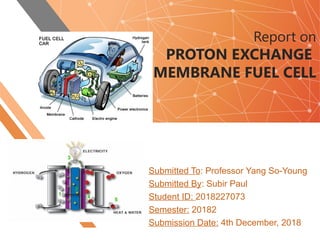
- 1. Report on PROTON EXCHANGE MEMBRANE FUEL CELL Submitted To: Professor Yang So-Young Submitted By: Subir Paul Student ID: 2018227073 Semester: 20182 Submission Date: 4th December, 2018
- 2. Fuel Cells 2 A fuel cell can be defined as a galvanic cell that converts the chemical energy straight into electrical energy. This energy conversion device generates DC (Direct current) electricity from electro-chemical reaction of various chemical fuels. This electrochemical device does not burn fuels, but fuses them with oxygen to produce water. This one step electro-chemical reaction is obstructed by an electrolyte, which puts apart the two reactants. Consequently, two half reactions take place at the electrode Anode Reaction: 2H2 + 2O2 − → 2H2O + 4e− Cathode Reaction: O2 + 4e− → 2O2 − Overall Cell Reaction: 2H2 + O2 → 2H2O The ions only transfer through the electrolyte to the other electrolyte. The fuel cell is a sample robust system that contains only four active elements: cathode, anode, electrolyte and interconnect. Fuel cells show following eight significant advantage over combustion-based heat engines or conventional electricity generations: 1.Single step (form chemical to electrical energy)process. 2.No to negligible (if fossil fuels are used) air pollution and useful byproduct e.g. water. 3.Higher efficiency than diesel or gas engines (Theoretically 100% efficiency but practically 80% efficiency can be achieved in high temperature turbine hybrid systems that can exploit the generated heat). 4.Consistent efficiency at small load. 5.Reduced weight, particularly in mobile applications. 6.Low maintenance cost owing to no moving parts. 7.No sound pollution compared to internal combustion engines . 8.Quit compatible with contemporary energy carriers such as hydrogen and sources of renewable energy.
- 3. 3 Though the very first crude fuel cell was developed by William Grove exactly 179 years ago from now, because of the technical difficulties and lack of appropriate materials there are still not deemed as commercially feasible product. Classification of Fuel Cells
- 4. 4 Proton Exchange Membrane Fuel Cells Proton Exchange Membrane Fuel Cells (PEMFC) are promising contender as the next generation energy source because of their striking features including high energy density, low operating temperature, easy scale up and zero environmental pollution. The key component of PEMFCs is the polymeric proton exchange membrane (PEM) which serves as a solid electrolyte. In presence of water, the PEM swells and its acidic functional groups dissociate to form protons free to move throughout the membrane; thus the conductivity of PEM comes about. PEMFCs also use platinum- based materials as catalyst. In early 1960s, the initial version of a PEMFC was build for the Gemini spacecraft. Owing to short lifetime of the membrane and high cost, in that time its uses excluded in fields other than space flight. Following a dormant phase lasting nearly three decades, some remarkable progress in PEMFC properties were acquired due to an amalgamation of two major aspects: I.Innovation of Nafion as PEM and II.Introduction of a new catalyst-ink techniques for electrode fabrication, which simultaneously increased the efficiency and reduced the amount of platinum catalyst. Working Principal of PEMFC
- 5. Efficiency of PEMFC The PEMFC efficiency can be defined as the ratio between cell output voltage and theoretical cell potential. The electrical work, Wel , generated in a fuel cell is limited by Gives free energy, ΔG, i.e,. Wel = -ΔG Theoretical potential of fuel cell, E = ΔG/nF Where, n = electrons involved in cathode reaction, F = Faraday’s constant. At 25 C , E =⁰ ΔG/nF = 237,340 J mol-1 / (2 X 96,485 As mol -1) = 1.23 Volt. So, efficiency of PEMFC = actual cell potentials/1.23 Volts X 100% Real time potential are thus always smaller compared to the theoretical cell potentials because of the irreversible voltage losses. These losses are mainly attributable to three factors such as I.Activation losses (losses owing to sluggish electrode kinetics) II.Ohmic losses (losses caused by resistance to ion and electron flow through membrane electrode assembly (MEA) and stack's electrically conductive components, respectively) III.Concentration losses (losses because of mass transport i.e., when a reactant (i.e., hydrogen or oxygen) is more quickly used up than supplied). Components of PEMFC and Their Functions In a single cell of PEMFC, major hardware components are Membrane Electrode Assembly (MEA), gaskets and bipolar plates. As single MEA, power house of PEMFC, generates only <1 volt under ordinary operating conditions, hence multiple MEAs are stacked in series to generate a practical voltage output. Each Cell in a stack is sandwiched amid two bipolar plates to isolate it from adjacent cells. Bipolar plates are typically built with metal, carbon (graphite) or composites.
- 6. It possesses grooved channels, called ''flow field'', in their structure, which allow gases to flow over the MEA. Inside all bipolar plates, additional channels are present for liquid coolant circulation. Around the edges of the MBA, gaskets made of a rubbery polymer are added to prevent gas leakage. Table 2 discusses about the functions of components of PEMFC. Components Functions PEM (Electrolyte) Allows protons transfer from anode to cathode. Separates two half reactions i.e., oxidation and reduction. Electrocatalyst (Electrode) Lowers the activation energy and thus facilitates the reaction of oxygen and hydrogen i.e., increases the reaction rate or lowers the operating temperature. Gas Diffusion Layer (GDL) Permits uniform diffusion of reactants toward catalyst layer. Allows electron conduction from anode to cathode. Let out the water and heat produced by electrochemical reaction at the cathode. Supports MEA structure. Bipolar plate Guides reactant gases through flow channels toward respective electrodes. Leads the way 0ut for generated heat and water. Partitions reactant gases in adjacent cells. Acts as inner structural support for PEMFC stack. Current collector Passes collected current in/out of external circuit. End plates Gives enough contact pressure in PEMFC stack with the intention of preventing reactants from leaking and reducing contact resistance between layers. Gaskets Seal the fluid escapes to keep them in their respective zones in PEMFC. Heating/Cooling Plates Controls the optimum temperature for operation of PEMFC Reactant gases manifold Delivers reactants to each cell.
- 7. Proton Exchange Membrane A PEM isolates the anode and cathode to avoid direct contact between oxidation and fuel. But its main purpose is to conduct protons only and block the electrons. It incorporates numerous proton conductive functional groups that allow protons to move from one group to another. A good PEM should at least have following seven criteria: a.High proton conductivity, b.Sufficient mechanical strength, c.Chemical, electrochemical and thermal stability under operating conditions d.Very little hydrogen and oxygen by-pass e.Low cost f.Thin-film formability, and g.Overall compatibility with other cell components. Nafion® Membrane Nafion®, in fact, is the most operated and designated PEM for PEMFCs and DMFCs. Between 1960 and 1980, the U.S. chemical company Du Pont de Numerous began delivery of ion-exchange membranes of a new type trade-named Nafion®. Nafion® not only exhibited a twofold increment in specific conductivity of the membrane but also extended the life time by four orders of magnitude (104 to 105 h). Nafion® is a synthetic polymer incorporating perflurovinyl ether groups terminated with sulfonate group. In contact of water, Nafion® segregates into hydrophilic domains and hydrophobic fluorocarbon domains. Based on the thickness of the commercial Nafion® membrane, DuPont have launched several types of Nafion® membranes such as Nafion® 105, 112, 1135, 115, 117 and 1110. Among these, Nafion® 117 is mainly used for its easy modification.
- 8. Proton Conducting Mechanism Proton conduction mechanism in Nafion® membrane can be divided into two sections: Proton conduction in surface and bulk. Surface transport mechanism can be explained by two mechanism: Grotthuss and Vehicle mechanism. The variation of relative humidity (RH) in membrane decides the proportion of proton conductivity on the basis of the Grotthuss and vehicle mechanisms. In vehicle mechanism, proton propagates together with H20 molecules by complex formation (for example H3O+ form) and for this required number of water molecules are small. On the contrary, in Grotthuss mechanism, proton transfers by proton hopping from one proton carrier site to an adjacent one through hydrogen bonds.
- 9. Water Content of Nation® Membrane The pores of Nation® can hold water in considerable amount. The water content λ of Nation® is a very significant value and can be determined by experimental data using following equation: λ = (water molecules) absorbed / (Sulfonic acid groups) total MOF Crystals as Filler Materials of PEMs Metal-organic frameworks (M0Fs) are one of the most attractive and a fairly new group of porous, highly crystalline, coordination polymers which contain metal centers joined with organic linker by coordination bonds. Among their lots of diverse applications, MOFs act as promising candidates for electrolyte materials of fuel cells because of their controllable structure, large surface area and desirable electrochemical properties. Usually, the inorganic nodes in the structure contain ions of metal such as Al3+ , Co2+ , Cr3+ , Cu+ , Cu2+ , Fe3+ , Mn2+ , Zn2+ and Zr4+ or secondary building units (SBUs) consist of nearly all transition metals, Group-I and Group-IIA metals, lanthanides and actinides. The general organic linkers include negative functional groups like carboxylate, pyridyl, phosphonate, imidazolate or other azolate in their bi-, tri- or tetratopic forms.
- 10. Electrocatalysts An electrocatalyst is a chemical substance that increase the rate of an electrochemical reaction without being consumed in the process; after the reaction, it can potentially be recovered from the reaction mixture and is chemically unchanged. The electrocatalyst lowers the activation energy required, allowing the reaction to proceed more quickly or at a lower temperature. In a fuel cell, the electrocatalyst facilitates the reaction of oxygen and hydrogen. It is usually made of platinum powder very thinly coated onto carbon paper or cloth. Instead of Pt, Pt-alloys can be used as electrocatalyst. An electrocatalyst is rough and porous so the maximum surface area of the platinum can be exposed to the hydrogen or oxygen. The platinum-coated side of the catalyst faces the membrane in the fuel cell. Chemical and Physical Characterization Structural Study XRD Analysis Surface Morphology BET Analysis Thermal Stability Mechanical Stability Oxidative Stability Water Uptake Ion Exchange Capacity Proton Conductivity Performance Test in Single Cell