A Brief Review Of High-Entropy Films
•
0 likes•19 views

Professional Writing Service http://StudyHub.vip/A-Brief-Review-Of-High-Entropy-Films 👈
![However, due to the limitations of the alloy entropy, the traditional
metal nitride, carbide, and oxide film which are low-entropy films,
could not meet the increasing requirements criteria. With the
development of HEAs, researchers have focused on study about
high-entropy films (HEFs). HEFs not only possess the excellent
performance as HEAs, even some of the performances have been
enhanced. These alloy films have shown major application poten-
tials in the fields of solar thermal conversion systems [1], high
hardness coating [2], corrosion resistant coating [3], diffusion bar-
riers in the integrated circuit (IC) systems [4], etc.
2. Emergence and development of HEFs
Since the concept of HEAs was published in 2004, the study of
HEFs has been subsequently developed. HEFs was reported in 2005,
when Chen et al. [5] first prepared FeCoNiCrCuAlMn and FeCo-
NiCrCuAl0.5 nitride film through magnetron sputtering, and
explored the change of phase structure with the nitrogen flow rate.
Then, Huang et al. [6] prepared AlCoCrCu0.5NiFe oxide film, and
analyzed the phase structure, hardness, and phase stability. With
the continuing development of HEFs, Tsai et al. [7] applied
AlMoNbSiTaTiVZr film to the diffusion barrier between Cu and Si
wafer. The experimental results showed that the films have major
application potential. In recent years, high-entropy coatings pre-
pared by laser cladding have gradually developed. Through laser
cladding, Zhang et al. [8,9] prepared NiCoFeCrAl3 and FeCoNiCrAl2Si
high entropy coatings.
At present time, the HEFs are mainly including nitride-films and
oxide-films. The principle of the HEFs composition design is similar
to that of HEAs. Generally speaking, the elements of HEAs can be
divided into “basic element” and “functional element” as shown in
Fig. 1. For example, Cr, Fe, Co, Ni, and Cu, along with other elements,
can be referred to as the base elements, since they do not have large
differences in atomic size, and tend to form simple face-centered
cubic (FCC) or body-centered cubic (BCC) solid-solution struc-
tures. Meanwhile, Ti, V, and W, which have excellent thermal sta-
bility and corrosion resistance properties, can be referred to as the
functional elements. According to the performance requirements,
the function elements can be added into the base elements. In
addition, a number of non-metallic elements, such as C, N, and B,
can also be added, which can fill interstitial positions of films, in
order to improve the hardness characteristics.
3. Preparation of HEFs
The preparation methods of films can mainly be divided into
two categories: physical methods, and chemical methods, which
are shown in Fig. 2. Physical preparation mainly refers to physical
vapor deposition (PVD), including vacuum sputtering, vacuum
evaporation, and ion plating. Meanwhile, chemical preparation
mainly includes chemical vapor deposition (CVD), and the liquid
phase deposition (LPD).
At the present time, the following methods of preparing HEFs
have been reported: magnetron sputtering method [10e13], laser
cladding [8,9,14,15], electrochemical deposition [16], arc thermal
spraying [17], cold spraying [18], electron beam evaporation
deposition [19], and plasma cladding [7]. Among them, magnetron
sputtering and laser cladding are the most mature techniques for
the preparation of HEFs. Table 1 summarizes the characteristics of
the two technologies.
The principle of magnetron sputtering deposition is a sputtering
effect. The high energy particles bombard the surface of the target
(Fig. 3), making the target atoms escape and move along a certain
direction, and eventually thin film forms on the substrate [20]. The
dual function of magnetic and electric fields increases the collision
probabilities of the electron, charged particles, and gas molecules.
In the usual cases, the magnetron sputtering target material is
prepared by the arc melting and powder-metallurgy methods. If
the melting point of each principal component is relatively
different, a powder metallurgy method is usually the priority
choice. Also, it is difficult to obtain an equiatomic ratio thin film,
since the different elements have different sputtering output ca-
pacities. Therefore, the “multi-target sputtering” has been pro-
posed [21]. According the composition design of HEFs, many single
element targets or alloy targets can be prepared, and the atomic
ratio of elements can be controlled by adjusting the target sput-
tering power.
Laser cladding technology is pointed out that melting metal
powder which features certain physical, chemical, or mechanical
properties by high-power and high-speed laser. A layer combining
with the matrix in the way of metallurgy bonding can improve the
mechanical properties between the layer and matrix. Laser clad-
ding technology is divided into two types of methods, referred to as
pre-powder and synchronous feeding, as shown in the schematic
diagram of Fig. 4.
4. Phase structure
The composition design of the HEFs is consistent with the HEAs.
Therefore, the HEFs also has a “high entropy effect”. In addition, the
film cooling rate is relatively fast, and it tends to form an amor-
phous phase or simple FCC, BCC solid solution phase. In this section,
Fig. 1. Composition design of HEFs.
Fig. 2. Classification of thin film processing (Electrochemical (EC) deposition, Liquid
phase epitaxy (LPE), Arc ion plating (AIP), Molecular beam epitaxy (MBE), Direct cur-
rent sputtering (DCS), Radio frequency sputtering (RFS)).
X.H. Yan et al. / Materials Chemistry and Physics 210 (2018) 12e19 13](data:image/gif;base64,R0lGODlhAQABAIAAAAAAAP///yH5BAEAAAAALAAAAAABAAEAAAIBRAA7)
Recommended
More Related Content
Similar to A Brief Review Of High-Entropy Films
Similar to A Brief Review Of High-Entropy Films (20)
More from Sophia Diaz
More from Sophia Diaz (20)
Recently uploaded
Recently uploaded (20)
A Brief Review Of High-Entropy Films
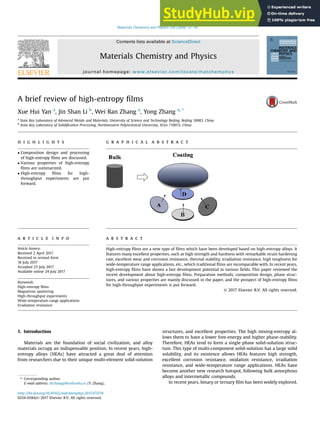
- 1. A brief review of high-entropy films Xue Hui Yan a , Jin Shan Li b , Wei Ran Zhang a , Yong Zhang a, * a State Key Laboratory of Advanced Metals and Materials, University of Science and Technology Beijing, Beijing 10083, China b State Key Laboratory of Solidification Processing, Northwestern Polytechnical University, Xi'an 710072, China h i g h l i g h t s g r a p h i c a l a b s t r a c t Composition design and processing of high-entropy films are discussed. Various properties of high-entropy films are summarized. High-entropy films for high- throughput experiments are put forward. a r t i c l e i n f o Article history: Received 2 April 2017 Received in revised form 18 July 2017 Accepted 23 July 2017 Available online 24 July 2017 Keywords: High-entropy films Magnetron sputtering High-throughput experiments Wide-temperature-range applications Irradiation resistance a b s t r a c t High-entropy films are a new type of films which have been developed based on high-entropy alloys. It features many excellent properties, such as high strength and hardness with remarkable strain hardening rate, excellent wear and corrosion resistance, thermal stability, irradiation resistance, high toughness for wide-temperature range applications, etc., which traditional films are incomparable with. In recent years, high-entropy films have shown a fast development potential in various fields. This paper reviewed the recent development about high-entropy films. Preparation methods, composition design, phase struc- tures, and various properties are mainly discussed in the paper, and the prospect of high-entropy films for high-throughput experiments is put forward. © 2017 Elsevier B.V. All rights reserved. 1. Introduction Materials are the foundation of social civilization, and alloy materials occupy an indispensable position. In recent years, high- entropy alloys (HEAs) have attracted a great deal of attention from researchers due to their unique multi-element solid-solution structures, and excellent properties. The high mixing-entropy al- lows them to have a lower free-energy and higher phase-stability. Therefore, HEAs tend to form a single phase solid-solution struc- ture. This type of multi-component solid-solution has a large solid solubility, and its existence allows HEAs features high strength, excellent corrosion resistance, oxidation resistance, irradiation resistance, and wide-temperature range applications. HEAs have become another new research hotspot, following bulk amorphous alloys and intermetallic compounds. In recent years, binary or ternary film has been widely explored. * Corresponding author. E-mail address: drzhangy@ustb.edu.cn (Y. Zhang). Contents lists available at ScienceDirect Materials Chemistry and Physics journal homepage: www.elsevier.com/locate/matchemphys http://dx.doi.org/10.1016/j.matchemphys.2017.07.078 0254-0584/© 2017 Elsevier B.V. All rights reserved. Materials Chemistry and Physics 210 (2018) 12e19
- 2. However, due to the limitations of the alloy entropy, the traditional metal nitride, carbide, and oxide film which are low-entropy films, could not meet the increasing requirements criteria. With the development of HEAs, researchers have focused on study about high-entropy films (HEFs). HEFs not only possess the excellent performance as HEAs, even some of the performances have been enhanced. These alloy films have shown major application poten- tials in the fields of solar thermal conversion systems [1], high hardness coating [2], corrosion resistant coating [3], diffusion bar- riers in the integrated circuit (IC) systems [4], etc. 2. Emergence and development of HEFs Since the concept of HEAs was published in 2004, the study of HEFs has been subsequently developed. HEFs was reported in 2005, when Chen et al. [5] first prepared FeCoNiCrCuAlMn and FeCo- NiCrCuAl0.5 nitride film through magnetron sputtering, and explored the change of phase structure with the nitrogen flow rate. Then, Huang et al. [6] prepared AlCoCrCu0.5NiFe oxide film, and analyzed the phase structure, hardness, and phase stability. With the continuing development of HEFs, Tsai et al. [7] applied AlMoNbSiTaTiVZr film to the diffusion barrier between Cu and Si wafer. The experimental results showed that the films have major application potential. In recent years, high-entropy coatings pre- pared by laser cladding have gradually developed. Through laser cladding, Zhang et al. [8,9] prepared NiCoFeCrAl3 and FeCoNiCrAl2Si high entropy coatings. At present time, the HEFs are mainly including nitride-films and oxide-films. The principle of the HEFs composition design is similar to that of HEAs. Generally speaking, the elements of HEAs can be divided into “basic element” and “functional element” as shown in Fig. 1. For example, Cr, Fe, Co, Ni, and Cu, along with other elements, can be referred to as the base elements, since they do not have large differences in atomic size, and tend to form simple face-centered cubic (FCC) or body-centered cubic (BCC) solid-solution struc- tures. Meanwhile, Ti, V, and W, which have excellent thermal sta- bility and corrosion resistance properties, can be referred to as the functional elements. According to the performance requirements, the function elements can be added into the base elements. In addition, a number of non-metallic elements, such as C, N, and B, can also be added, which can fill interstitial positions of films, in order to improve the hardness characteristics. 3. Preparation of HEFs The preparation methods of films can mainly be divided into two categories: physical methods, and chemical methods, which are shown in Fig. 2. Physical preparation mainly refers to physical vapor deposition (PVD), including vacuum sputtering, vacuum evaporation, and ion plating. Meanwhile, chemical preparation mainly includes chemical vapor deposition (CVD), and the liquid phase deposition (LPD). At the present time, the following methods of preparing HEFs have been reported: magnetron sputtering method [10e13], laser cladding [8,9,14,15], electrochemical deposition [16], arc thermal spraying [17], cold spraying [18], electron beam evaporation deposition [19], and plasma cladding [7]. Among them, magnetron sputtering and laser cladding are the most mature techniques for the preparation of HEFs. Table 1 summarizes the characteristics of the two technologies. The principle of magnetron sputtering deposition is a sputtering effect. The high energy particles bombard the surface of the target (Fig. 3), making the target atoms escape and move along a certain direction, and eventually thin film forms on the substrate [20]. The dual function of magnetic and electric fields increases the collision probabilities of the electron, charged particles, and gas molecules. In the usual cases, the magnetron sputtering target material is prepared by the arc melting and powder-metallurgy methods. If the melting point of each principal component is relatively different, a powder metallurgy method is usually the priority choice. Also, it is difficult to obtain an equiatomic ratio thin film, since the different elements have different sputtering output ca- pacities. Therefore, the “multi-target sputtering” has been pro- posed [21]. According the composition design of HEFs, many single element targets or alloy targets can be prepared, and the atomic ratio of elements can be controlled by adjusting the target sput- tering power. Laser cladding technology is pointed out that melting metal powder which features certain physical, chemical, or mechanical properties by high-power and high-speed laser. A layer combining with the matrix in the way of metallurgy bonding can improve the mechanical properties between the layer and matrix. Laser clad- ding technology is divided into two types of methods, referred to as pre-powder and synchronous feeding, as shown in the schematic diagram of Fig. 4. 4. Phase structure The composition design of the HEFs is consistent with the HEAs. Therefore, the HEFs also has a “high entropy effect”. In addition, the film cooling rate is relatively fast, and it tends to form an amor- phous phase or simple FCC, BCC solid solution phase. In this section, Fig. 1. Composition design of HEFs. Fig. 2. Classification of thin film processing (Electrochemical (EC) deposition, Liquid phase epitaxy (LPE), Arc ion plating (AIP), Molecular beam epitaxy (MBE), Direct cur- rent sputtering (DCS), Radio frequency sputtering (RFS)). X.H. Yan et al. / Materials Chemistry and Physics 210 (2018) 12e19 13
- 3. the current study on the phase structure of HEFs prepared by magnetron sputtering and laser cladding are mainly analyzed. In particular, during the process of magnetron sputtering, different process parameters such as nitrogen flow rates, substrate bias, and substrate temperatures can play an important role on the phase structure of the HEFs. 4.1. Phase structure of the HEFs prepared by magnetron sputtering 4.1.1. N2 flow rate The N2 flow rate has a significant effect on the phase structure of the HEFs. Under the conditions of low nitrogen gas flow rate, it has been found that the HEFs tends to form an amorphous structure. Chang et al. [13] reported that the TiVCrAlZr films exhibited amorphous structures at low nitrogen gas flow rates (Fig. 5). However, with increases the N2 flow rate, the HEFs phase structure transforms from an amorphous to a simple FCC solid solution structure. Liang et al. [22] found a similar phenomenon in the preparation of TiVCrZrHf nitride films. When the N2 flow rate was between 0 and 2 standard cubic cm per minute (SCCM), the XRD pattern of the film showed a broad diffraction peak. This phe- nomenon indicated that the phase structure of the TiVCrZrHf film was amorphous as shown in Fig. 6. With increases in the nitrogen flow rate, the phase structure also changed from an amorphous phase to a FCC solid solution phase. In addition, many HEFs have been reported to have similar results, such as AlCrTaTiZr [23], AlCrMoSiTi [24], and TiAlCrSiV [25] films. It could be seen that the phase structures of the HEFs were transiting from an amorphous to simple solid solution with the increases of N2 flow rates. The main reason for this phenomenon is that, as the nitrogen flow rate increased, more and more binary nitrides were formed. For example, the (TiVCrZrHf)N thin films contain many binary nitrides, such as TiN, VN, CrN, ZrN and HfN, which were formed with the increase of the nitrogen flow rate. These nitrides are FCC structures, and therefore the structure of the FCC is obvious in the XRD pattern. Another reason is that the larger nitrogen flow rate tended to increase the mobility of the atoms, and ensured the growth and diffusion of the grains. In addition, with the increase of the N2 flow rates, the thicknesses of the film became thinner, which was mainly due to the increased nitrogen content. Meanwhile, the argon content decreased, and the number of argon ions reduced. Therefore, the sputtering frequency was reduced, and the deposition rate was slow. Table 1 Features of the magnetron sputtering and laser cladding. Methods of preparation Advantages Disadvantages Magnetron sputtering 1) The substrate temperature rises slowly, and the deposition rate of the film is high; 2) The film has good consistency and a compact structure; 3) Good compatibility with the substrate; 4) The performance and thickness of the film can be flexibly controlled by the parameters. 1) Target utilization is low; 2) Film thickness is limited Laser cladding 1) High heating and cooling rates; 2) The thermal effect on the substrate is low; 3) The grains are small and uniform; 4) The coating is combined with the matrix for metallurgy, and a high bonding strength is achieved; 5) The thickness is up to several millimeters. 1) Easily produces various defects; 2) The surface is not flat; 3) A cracking sensitivity of the cladding layer is evident. Fig. 3. Schematic of the magnetron sputtering process. (a) (b) Fig. 4. Schematic of laser cladding: (a) Synchronous powder; (b) Pre-powder layer. X.H. Yan et al. / Materials Chemistry and Physics 210 (2018) 12e19 14
- 4. 4.1.2. Substrate bias The substrate bias is an effective method to improve the struc- ture and properties of films. Shen et al. prepared (Al1.5CrNb0.5Si0.5Ti) Nx thin films by magnetron sputtering tech- niques [11] and investigated the effects of substrate bias (Vs) on the phase structures of films. It was found that the phase structures of the films tended to form simple FCC structures. With the change of Vs, the crystal diffraction peak became gradually weakened, and the structure slowly changed from simple columnar crystal to a dense phase structure. At the same time, the grain was refined, and the grain size decreased from 70 nm to 5 nm. Huang et al. [12] also studied the effects of substrate bias on the phase structure of HEFs. The results show that when the Vs were weakened, the phase structure tended to be amorphous. With the increase of the Vs, the energy of ion bombard the target was increased, therefore both the ability of target atoms diffusion and participation in the chemical reactions can be facili- tated. The film's density and film-forming ability were also improved. With the improvements in the film's density and film- forming ability, the high energy bombardment induced various defects in the film, and also inhibited the growth of columnar crystals and refinement of the film grains. 4.1.3. Substrate temperature Along with the substrate bias and the N2 flow rates, the tem- perature of the substrate also was found to have a significant effect on the phase structure of the HEFs. Huang et al. [26] prepared AlCrNbSiTiV nitride film with a substrate temperature between 100 C and 500 C. The results indicated that the phase structure was a single-phase FCC structure (Fig. 7a). In addition, as the sub- strate temperature increased, the size of grain became larger (Fig. 7b), especially at between 100 C and 300 C. Liang et al. also got the same conclusion, with the increase temperature of the substrate, the high entropy nitride film still presented a simple FCC solid solution phase structure. Overall, the grain size shows an increasing trend. It was concluded that the main reason for the phenomenon was that the increasing substrate temperatures enhanced the adsorp- tion capacity and surface mobility of the atoms. Therefore, the grains grew easily. The lattice constants show a tendency to decrease, which may have been due to multiple factors, such as phase separations and residual stresses. 4.2. Phase structure of the HEFs prepared by laser cladding Currently, laser cladding technology is one of the most common ways to prepare the surface coating of a work piece. Similarly, due 2 (degree) Intensity (Arb Units) Fig. 5. XRD patterns of TiVCrAlZr films with different N2 flow rates [13]. 2 (degree) Intensity (Arb Units) Fig. 6. XRD patterns of the TiVCrZrHf films with different N2 flow rates [22]. (a) (b) 2 (degree) Substrate temperature Intensity (Arb Units) Grian size (nm) Lattice constant (A) Fig. 7. (a) XRD patterns of the AlCrNbSiTiV nitride films at different substrate temperatures; (b) Variations of the grain sizes and lattice constant of the AlCrNbSiTiV nitride film at different substrate temperatures [26]. X.H. Yan et al. / Materials Chemistry and Physics 210 (2018) 12e19 15
- 5. to the “high entropy effect”, HEFs which are prepared by laser cladding technology tend to form simple FCC and BCC solid solution structures. Yeh et al. [27] prepared a CrMnFeCoNi coating by laser cladding, and analyzed its microstructure and corrosion resistance. The XRD results indicated that the phase structure of the HEAs coating was mainly a simple FCC solid solution phase. Boron is a common element which is used to improve the hardness of a coating. After adding the B element, the phase structure of the HEFs will not only have the simple solid solution phase of an FCC and BCC, but also an alloy boride phase will exist. Lin et al. [28] reported that, with increases in boron content, the phase structure of FeCoCrNiAlBx HEAs coating had both FCC and BCC phases, along with a large amount of boride (Fig. 8). It has shown the FeCoCrNiB HEFs with high wear resistance, Huang et al. [29] also reported the presence of alloy boride phases. Titanium is a common element which is used to improve the corrosion resistance and high temperature performance of coatings. Following the addition of Ti, a titanium alloy was pre- sented in the HEFs phase structure. Zhang et al. [30] studied high-temperature TiZrNbWMo HEAs coatings, and the XRD pat- terns showed that the phase structure of the coating included a mainly simple BCC solid solution phase, and a TixW1-x precipi- tated phase. 5. Mechanical properties Comparing with traditional alloy films, the HEFs have excellent mechanical properties. Table 2 summarizes the hardness and modulus of HEFs which have been reported. As mentioned in Part 2, by adding N and other elements, the hardness of the HEFs can be further enhanced. It can also be seen in Fig. 9 the hardness and modulus of the nitride films showed a rising trend. In addition to the effects of the elemental content, the hardness of the HEFs is affected by the sputtering power and substrate temperatures. Ren et al. [42] explored the effects of the magnetron sputtering parameters on the hardness and modulus of HEFs. It was found that, as the sputtering power increasing, the hardness and modulus increased from 13.1 and 200 GPa to 15.2 and 221 GPa, respectively (Fig. 10a). Subse- quently, the hardness and modulus display slightly downward trends. However, with increases in the substrate temperature, the hardness and modulus of the film display a single rising trend (Fig. 10b). 6. Thermal stability The HEFs has displayed excellent thermal stability. Even at high temperatures, it has been found to still maintain high strength and phase structure stability. Zhang et al. [43] reported that the hardness of a CoCrCuFeNi coating displayed almost no changes after annealing at 500 C for five hours (Fig. 11a). That which annealed at 750 C for five hours decrease in hardness by 5.5%, and it was maintained at 1000 C for five hours, the hardness was higher than the alloy prepared by vacuum melting. In addition, their study also explored phase stability at high temperatures (Fig. 11b). The phase structure of the CoCrCuFeNi HEAs coating was a simple FCC solid solution phase, after annealing at 500 C, and at 750 C for five hours, the phase structure did not change significantly. Table 3 summarizes the high temperature perfor- mance of the HEFs. 7. Corrosion resistance The HEFs are usually composed of elements such as Ni, Cr, Co, Ti, and Cu, therefore HEFs not only feature excellent mechanical properties, but also can show a good corrosion resistance to high concentrations of acid. Ren et al. [50] studied the corrosion behavior of a CuCrFeNiMn coating by immersion test and potenti- ometric polarization measurement method. The results showed Intensity (Arb Units) 2 (°) 2 (degree) Fig. 8. XRD pattern of FeCoCrNiAlBx coatings [28]. Table 2 Hardness and modulus of the HEFs. Composition Hardness (GPa) Modulus (GPa) Reference FeCoNiCuVZrAl 12.0 166 [31] Al0CoCrCuFeNi 15.4 203.8 [32] Al2.5CoCrCuFeNi 16.5 218.3 [32] AlCrNiSiTi 12.9 141.2 [33] AlCrSiTiZr 11.5 ~203 [34] (AlCrSiTiZr)N 17 ~231 [34] (AlCrTaTiZr)N 23.9 234.77 [35] (AlCrMoTaTiZr)N 40.2 ~385.0 [36] (AlCrTaTiZr)N 30.0 293.1 [37] (TiVCrZrHf)N 23.8 267.3 [22] (AlCrNbSiTiV)N 42 350 [12] (TiHfZrVNb)N 44.3 384 [38] (AlCrTaTiZr)N 20 242 [39] (NbTiAlSi)N 20.5 206.8 [40] (AlCrTaTiZr)N 30 350 [41] Yong’s modulus (GPa) Hardness (GPa) Fig. 9. The hardness and Yong's modulus of HEFs with and without N. X.H. Yan et al. / Materials Chemistry and Physics 210 (2018) 12e19 16
- 6. that when the coating immersed in 1 mol/L of sulfuric acid solution for 100 h at the 25 C, the corrosion rate of the CuCrFeNiMn coating was only 0.074 mm/y, which was much lower than that of 304 stainless steel (1.710 mm/y). Yeh et al. also did a similar work [51]. Both CrMnFeCoNi coating and 304 stainless steel was immersed in a 3.5% NaCl solution, and 0.5 mol/L of H2SO4. The experimental results showed that the corrosion resistance of the HEAs coating was better than that of A316 steel, and the corrosion current was even lower than that of the 304-stainless steel. Qiu et al. [52] compared an AlCrFeNiCoCu coating with 304 stainless steel, and also obtained similar conclusions. 8. HEFs for high-throughput experiments As we all know, material science is developed on the basis of experiments. In the process of scientific exploration, the method which relies on scientific intuition and “trial error” method has been formed. The kind research method can inevitably lead to the shortcoming of time-consuming, long cycle of research and low-efficiency, etc. In the 1970s, Hanak proposed an experimental scheme with a “high-throughput” feature firstly [53]. So far, it has been developed 40 years for high-throughput preparation, various forms of materials such as film, bulk, and (a) (b) Hardness (GPa) Yong ’ s Modulus (GPa) Hardness (GPa) Yong ’ s Modulus (GPa) Sputtering power (W) Substrate temperature (K) Fig. 10. Variations hardness and modulus of the (AlCrMnMoNiZr)N films with: (a) Sputtering power; (b) Substrate temperature [42]. (a) (b) fcc 2 (degree) Annealing temperature ( ) Intensity (Arb Units) Hardness (Hv) Electrical resistivity cm) cm) Fig. 11. (a) Electrical resistivity and hardness changes with annealing temperature of CoCrCuFeNi films; (b) XRD patterns of CoCrCuFeNi films [43]. Table 3 Phase structures of the HEFs after annealing. Composition Temperature ( C) Time (hours) Phase structure Ref. Before annealing/after annealing (TiVCrZrHf)N 300 2 FCC/FCC [44] (AlBCrSiTi)N 700 2 Amorphous/Amorphous [45] (NbTiAlSiW)N 700 24 Amorphous/Amorphous [1] TaNbTiW 700 1.5 BCC/BCC [46] 6FeNiCoCrAlTiSi 750 5 BCC/BCC [47] FeCrNiCoMn 900 2 FCC þ BCC/FCC þ BCC [48] FeCoCrNiB 900 5 FCC þ M3B/FCC þ M3B [49] X.H. Yan et al. / Materials Chemistry and Physics 210 (2018) 12e19 17
- 7. powder, have achieved the high-throughput preparation. The film deposition is the most usual method for high- throughput preparation. It mainly includes co-deposition method [53], Separate template coating method [54], continuous phase diagram template coating method [55]. Among them, the co- deposition is the most suitable high-throughput preparation method for HEAs with multi-elements. Target atoms have a “dis- tance advantage” in the process of deposition, taking advantage of the different distance between targets and substrate, the proba- bility of target atoms depositing nearby is larger, therefore a film with a continuous composition gradient is formed on the substrate. Co-deposition technology is divided into single target co- deposition (Fig. 12) and multi-target co-deposition (Fig. 13). Both methods can achieve co-deposition of multiple elements. In com- parison, multi-target co-deposition is more controllable for each component content than single target co-deposition, and a larger gradient of composition can be obtained easier. According the composition design of HEAs, many single element targets or alloy targets can be prepared, and the atomic ratio of elements can be controlled by adjusting target sputtering power. And finally HEFs with a continuous composition gradient is obtained. Combined with high-throughput characterization techniques, we can achieve rapid screening of HEAs and HEFs. 9. Prospects The HEFs has been proven to have excellent mechanical prop- erties, and high temperature performance, as well as wear and corrosion resistance. The HEFs has shown great development po- tential in the fields of solar thermal conversion, surfaces of work piece engineering, and integrated circuit diffusion barriers. How- ever, there are still some problems involved in the research of the HEFs, as follows: (1) The composition design of the alloy is still in the form of a “cocktail”; (2) The studies about HEFs are mainly focused on the microstructure. The properties about corrosion resistance, wear resistance, and high temperatures stability have been less studied; (3) To date, there has been no complete phase formation rule to support the study of HEFs. Finally, this study believed that during the processes of HEFs film research, the method of “trial and error” should be abandoned. The composition selection and design of HEFs should be combined with simulated calculations. In addition, high throughput experiments should be taken into account. Developing purposeful and efficient research is the most effective way to promote the development of the HEFs. Acknowledgment The authors would like to thank the financial supports by the National Science Foundation of China (NSFC, Granted Nos. 51471025 and 51671020). References [1] W. Sheng, X. Yang, C. Wang, Y. Zhang, Nano-crystallization of high-entropy amorphous NbTiAlSiWxNy films prepared by magnetron sputtering, Entropy 18 (6) (2016) 226. [2] M. Zhang, X. Zhou, X. Yu, J. Li, Synthesis and characterization of refractory TiZrNbWMo high-entropy alloy coating by laser cladding, Surf. Coat. Technol. (2017) 321e329. [3] Y. Shon, S.S. Joshi, S. Katakam, R.S. Rajamure, N.B. Dahotre, Laser additive synthesis of high entropy alloy coating on aluminum: corrosion behavior, Mater. Lett. 142 (2015) 122e125. [4] S.Y. Chang, C.E. Li, S.C. Chiang, Y.C. Huang, 4-nm thick multilayer structure of multi-component (AlCrRuTaTiZr)N x as robust diffusion barrier for Cu in- terconnects, J. Alloys Compd. 515 (9) (2012) 4e7. [5] T.K. Chen, T.T. Shun, J.W. Yeh, M.S. Wong, Nanostructured nitride films of multi-element high-entropy alloys by reactive DC sputtering, Surf. Coat. Technol. 188e189 (1) (2004) 193e200. [6] Y.S. Huang, L. Chen, H.W. Lui, M.H. Cai, J.W. Yeh, Microstructure, hardness, resistivity and thermal stability of sputtered oxide films of AlCoCrCu 0.5 NiFe high-entropy alloy, Mater. Sci. Eng. A 457 (1e2) (2007) 77e83. [7] M.H. Tsai, J.W. Yeh, J.Y. Gan, Diffusion barrier properties of AlMoNbSiTaTiVZr high-entropy alloy layer between copper and silicon, Thin Solid Films 516 (16) (2008) 5527e5530. [8] H. Zhang, Y.Z. He, Y. Pan, Y.S. He, K.S. Shin, Synthesis and characterization of NiCoFeCrAl3 high entropy alloy coating by laser cladding, Adv. Mater. Res. 97e101 (2010) 1408e1411. [9] H. Zhang, Y. Pan, Y.Z. He, The preparation of FeCoNiCrAl 2 Si high entropy alloy coating by laser cladding, J. Metals Chin. 8 (2011) 1075e1079. [10] R.-S. Yu, C.-J. Huang, R.-H. Huang, C.-H. Sun, F.-S. Shieu, Structure and opto- electronic properties of multi-element oxide thin film, Appl. Surf. Sci. 257 (14) (2011) 6073e6078. [11] W.J. Shen, M.H. Tsai, Y.S. Chang, J.W. Yeh, Effects of substrate bias on the structure and mechanical properties of (Al 1.5 CrNb 0.5 Si 0.5 Ti)N x coatings, Thin Solid Films 520 (19) (2012) 6183e6188. [12] P.K. Huang, J.W. Yeh, Effects of substrate bias on structure and mechanical properties of (AlCrNbSiTiV)N coatings, J. Phys. D Appl. Phys. 42 (11) (2009) 115401e115407 (115407). [13] Z.C. Chang, S.C. Liang, S. Han, Y.K. Chen, F.S. Shieu, Characteristics of TiVCrAlZr multi-element nitride films prepared by reactive sputtering, Nucl. Instrum. Methods Phys. Res. 268 (16) (2010) 2504e2509. [14] H. Zhang, Y. Pan, Y.Z. He, The preparation of FeCoNiCrAl 2 Si high entropy alloy coating by Laser cladding, J. Metals Chin. (8) (2011) 1075e1079. [15] C. Huang, Y. Zhang, J. Shen, R. Vilar, Thermal stability and oxidation resistance of laser clad TiVCrAlSi high entropy alloy coatings on Tie6Ale4V alloy, Surf. Coat. Technol. 206 (6) (2011) 1389e1395. [16] C.Z. Yao, F.H. Wei, P. Zhang, X.H. Lu, P. Liu, Y.X. Tong, Facile preparation and magnetic study of amorphous Tm-Fe-Co-Ni-Mn multicomponent alloy nanofilm, J. Rare Earths 29 (2) (2011) 133e137. [17] Q. Li, T. Yue, Z. Guo, Electro-spark Deposition of Multi-element High Entropy Alloy Coating, ASM International, Member/Customer Service Center, Materials Park OH 44073-0002 United States, 2010. [18] S. Zhu, W.B. Du, X.M. Wang, J.K. Yao, Surface protection technology of mag- nesium alloy based on high entropy alloy, J. Armored Force Eng. Coll. Chin. 27 (6) (2013). [19] T.M. Yue, H. Xie, X. Lin, H. Yang, G. Meng, Microstructure of laser re-melted AlCoCrCuFeNi high entropy alloy coatings produced by plasma spraying, En- tropy 15 (7) (2013) 2833e2845. [20] F. Li, Y. Zhu, L.H. Li, Q.Y. Lu, J.H. Zhu, The development of magnetron sput- tering technology, Vac. Electron. Technol. Chin. 3 (2011) 49e54. [21] X. Feng, G. Tang, M. Sun, X. Ma, L. Wang, K. Yukimura, Structure and prop- erties of multi-targets magnetron sputtered ZrNbTaTiW multi-elements alloy Fig. 12. Schematic of single target co-deposition. Fig. 13. Schematic of multi-target co-deposition. X.H. Yan et al. / Materials Chemistry and Physics 210 (2018) 12e19 18
- 8. thin films, Surf. Coat. Technol. 228 (9) (2013) S424eS427. [22] S.C. Liang, D.C. Tsai, Z.C. Chang, H.S. Sung, Y.C. Lin, Y.J. Yeh, M.J. Deng, F.S. Shieu, Structural and mechanical properties of multi-element (TiVCrZrHf) N coatings by reactive magnetron sputtering, Appl. Surf. Sci. 258 (1) (2011) 399e403. [23] C.H. Lai, S.J. Lin, J.W. Yeh, S.Y. Chang, Preparation and characterization of AlCrTaTiZr multi-element nitride coatings, Surf. Coat. Technol. 201 (6) (2006) 3275e3280. [24] H.W. Chang, P.K. Huang, A. Davison, J.W. Yeh, C.H. Tsau, C.C. Yang, Nitride films deposited from an equimolar AleCreMoeSieTi alloy target by reactive direct current magnetron sputtering, Thin Solid Films 516 (18) (2008) 6402e6408. [25] C.H. Lin, J.G. Duh, J.W. Yeh, Multi-component nitride coatings derived from TieAleCreSieV target in RF magnetron sputter, Surf. Coat. Technol. 201 (14) (2007) 6304e6308. [26] P.K. Huang, J.W. Yeh, Effects of substrate temperature and post-annealing on microstructure and properties of (AlCrNbSiTiV)N coatings, Thin Solid Films 518 (1) (2009) 180e184. [27] Q. Ye, K. Feng, Z. Li, F. Lu, R. Li, J. Huang, Y. Wu, Microstructure and corrosion properties of CrMnFeCoNi high entropy alloy coating, Appl. Surf. Sci. 396 (2016) 1420e1426. [28] Lin D-y, Zhang N-n, He B, Zhang G-w, Zhang Y, Li D-y: tribological properties of FeCoCrNiAlB x high-entropy alloys coating prepared by laser cladding, J. Iron Steel Res. Int. 24 (2017) 184e189. [29] B. Huang, C. Zhang, H. Cheng, Q.H. Tang, H.C. Rao, P.Q. Dai, Microstructure and wear resistance of FeCoCr_xNiB high entropy alloy coating by laser cladding, China Surf. Eng. Chin. 27 (6) (2014) 82e88. [30] M. Zhang, X. Zhou, X. Yu, J. Li, Synthesis and characterization of refractory TiZrNbWMo high-entropy alloy coating by laser cladding, Surf. Coat. Technol. (2017) 321e329. [31] L. Liu, J.B. Zhu, C. Hou, J.C. Li, Q. Jiang, Dense and smooth amorphous films of multicomponent FeCoNiCuVZrAl high-entropy alloy deposited by direct cur- rent magnetron sputtering, Mater. Des. 46 (4) (2013) 675e679. [32] Z.F. Wu, X.D. Wang, Q.P. Cao, G.H. Zhao, J.X. Li, D.X. Zhang, J.J. Zhu, J.Z. Jiang, Microstructure characterization of Al x Co 1 Cr 1 Cu 1 Fe 1 Ni 1 ( x ¼ 0 and 2.5) high-entropy alloy films, J. Alloys Compd. 609 (609) (2014) 137e142. [33] T.K. Chen, T.T. Shun, J.W. Yeh, M.S. Wong, Nanostructured nitride films of multi-element high-entropy alloys by reactive DC sputtering, Surf. Coat. Technol. 188e189 (1) (2004) 193e200. [34] H.T. Hsueh, W.J. Shen, M.H. Tsai, J.W. Yeh, Effect of nitrogen content and substrate bias on mechanical and corrosion properties of high-entropy films (AlCrSiTiZr) 100 x N x, Surf. Coat. Technol. 206 (19e20) (2012) 4106e4112. [35] X. Wang, L. Wang, R.B. Li, Y.Y. Sun, M.D. Chen, Microstructure and mechanical properties of AlCrTaTiZrNx high entropy alloy nanometer coatings, Therm. Process. Technol. Chin. 16 (2015) 198e201. [36] K.H. Cheng, C.H. Lai, S.J. Lin, J.W. Yeh, Structural and mechanical properties of multi-element (AlCrMoTaTiZr)Nx coatings by reactive magnetron sputtering, Thin Solid Films 519 (10) (2011) 3185e3190. [37] S.Y. Chang, S.Y. Lin, Y.C. Huang, C.L. Wu, Mechanical properties, deformation behaviors and interface adhesion of (AlCrTaTiZr)N x multi-component coat- ings, Surf. Coat. Technol. 204 (20) (2010) 3307e3314. [38] A.D. Pogrebnjak, I.V. Yakushchenko, A.A. Bagdasaryan, O.V. Bondar, R. Krause- Rehberg, G. Abadias, P. Chartier, K. Oyoshi, Y. Takeda, V.M. Beresnev, Micro- structure, physical and chemical properties of nanostructured (TieHfeZreVeNb)N coatings under different deposition conditions, Mater. Chem. Phys. 147 (3) (2014) 1079e1091. [39] S.Y. Lin, S.Y. Chang, Y.C. Huang, F.S. Shieu, J.W. Yeh, Mechanical performance and nanoindenting deformation of (AlCrTaTiZr)NC y multi-component coat- ings co-sputtered with bias, Surf. Coat. Technol. 206 (24) (2012) 5096e5102. [40] Sheng W-J, Yang X, Zhu J, Wang C, Zhang Y: Amorphous phase stability of NbTiAlSiN X high-entropy films. Rare Met.:1e8. [41] C.H. Lai, M.H. Tsai, S.J. Lin, J.W. Yeh, Influence of substrate temperature on structure and mechanical, properties of multi-element (AlCrTaTiZr)N coatings, Surf. Coat. Technol. 201 (16e17) (2007) 6993e6998. [42] B. Ren, S. Lv, R. Zhao, Z. Liu, S. Guan, Effect of sputtering parameters on (AlCrMnMoNiZr)N films, Surf. Eng. 30 (2) (2014) 152e158. [43] H. Zhang, Y.Z. He, Y. Pan, S. Guo, Thermally stable laser cladded CoCrCuFeNi high-entropy alloy coating with low stacking fault energy, J. Alloys Compd. 600 (600) (2014) 210e214. [44] D.C. Tsai, Z.C. Chang, L.Y. Kuo, T.J. Lin, T.N. Lin, M.H. Shiao, F.S. Shieu, Oxidation resistance and structural evolution of (TiVCrZrHf)N coatings, Thin Solid Films 544 (4) (2013) 580e587. [45] C.W. Tsai, S.W. Lai, K.H. Cheng, M.H. Tsai, A. Davison, C.H. Tsau, J.W. Yeh, Strong amorphization of high-entropy AlBCrSiTi nitride film, Thin Solid Films 520 (7) (2012) 2613e2618. [46] X. Feng, G. Tang, L. Gu, X. Ma, M. Sun, L. Wang, Preparation and character- ization of TaNbTiW multi-element alloy films, Appl. Surf. Sci. 261 (1) (2012) 447e453. [47] H. Zhang, Y. Pan, Y. He, Effects of annealing on the microstructure and properties of 6FeNiCoCrAlTiSi high-entropy alloy coating prepared by laser cladding, J. Therm. Spray Technol. 20 (5) (2011) 1049e1055. [48] Z.Q. Wen, G. Dong, Q.L. Zhang, S.R. Guo, J.H. Yao, Effect of annealing on microstructure and properties of FeCrNiCoMn high entropy alloy coating by laser cladding, China Laser Chin. 3 (2014) 59e64. [49] Z.F. Huang, C. Zhang, Q.H. Tang, P.Q. Dai, B. Wu, Effect of annealing on microstructure and hardness of FeCoCrNiB high entropy alloy coating by laser cladding, Surf. Technol. Chin. 42 (1) (2013). [50] B. Ren, Z.X. Liu, D.M. Li, L. Shi, B. Cai, M.X. Wang, Corrosion behavior of CuCrFeNiMn high entropy alloy system in 1 M sulfuric acid solution, Mater. Corros. 63 (9) (2011) 828e834. [51] Q. Ye, K. Feng, Z. Li, F. Lu, R. Li, J. Huang, Y. Wu, Microstructure and corrosion properties of CrMnFeCoNi high entropy alloy coating, Appl. Surf. Sci. 396 (2017) 1420e1426. [52] X.W. Qiu, Microstructure and properties of AlCrFeNiCoCu high entropy alloy prepared by powder metallurgy, J. Alloys Compd. 555 (4) (2013) 246e249. [53] J.J. Hanak, The “multiple-sample concept” in materials research: synthesis, compositional analysis and testing of entire multicomponent systems, J. Mater. Sci. 5 (11) (1970) 964e971. [54] H. Chang, C. Gao, I. Takeuchi, Y. Yoo, J. Wang, P.G. Schultz, X.D. Xiang, R.P. Sharma, M. Downes, T. Venkatesan, Combinatorial synthesis and high throughput evaluation of ferroelectric/dielectric thin-film libraries for mi- crowave applications, Appl. Phys. Lett. 72 (17) (1998) 2185e2187. [55] S.S. Mao, High throughput growth and characterization of thin film materials, J. Cryst. Growth 379 (3) (2013) 123e130. X.H. Yan et al. / Materials Chemistry and Physics 210 (2018) 12e19 19