Assignment 2

This document contains 4 questions regarding thermodynamics assignments on topics like cogeneration power plants, combined gas-steam power cycles, refrigeration cycles, and isentropic nozzle flow of carbon dioxide. Question 1 involves a cogeneration plant with reheat and asks to draw a T-s diagram and determine the heat input and steam extraction fraction. Question 2 involves a combined gas-steam cycle and asks to determine moisture content, steam temperatures, net power output, and efficiency. Question 3 involves a refrigeration cycle and asks to determine quality, refrigeration load, COP, and theoretical maximum load. Question 4 involves isentropic nozzle flow of CO2 and asks to calculate properties at different pressures and comment on how increasing inlet pressure

Recommended
More Related Content
What's hot
What's hot (20)
Similar to Assignment 2
Similar to Assignment 2 (20)
More from Sijal Ahmed
More from Sijal Ahmed (20)
Recently uploaded
Recently uploaded (20)
Assignment 2
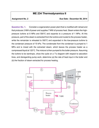
- 1. ME 234 Thermodynamics II Assignment No. 2 Due Date : December 08, 2014 Question No. 1. Consider a cogeneration power plant that is modified with reheat and that produces 3 MW of power and supplies 7 MW of process heat. Steam enters the high-pressure turbine at 8 MPa and 500°C and expands to a pressure of 1 MPa. At this pressure, part of the steam is extracted from the turbine and routed to the process heater, while the remainder is reheated to 500°C and expanded in the low-pressure turbine to the condenser pressure of 15 kPa. The condensate from the condenser is pumped to 1 MPa and is mixed with the extracted steam, which leaves the process heater as a compressed liquid at 120°C. The mixture is then pumped to the boiler pressure. Assuming the turbine to be isentropic, show the cycle on a T-s diagram with respect to saturation lines, and disregarding pump work, determine (a) the rate of heat input in the boiler and (b) the fraction of steam extracted for process heating.
- 2. Question No. 2. Consider a combined gas–steam power cycle. The topping cycle is a simple Brayton cycle that has a pressure ratio of 7. Air enters the compressor at 15°C at a rate of 10 kg/s and the gas turbine at 950°C. The bottoming cycle is a reheat Rankine cycle between the pressure limits of 6 MPa and 10 kPa. Steam is heated in a heat exchanger at a rate of 1.15 kg/s by the exhaust gases leaving the gas turbine and the exhaust gases leave the heat exchanger at 200°C. Steam leaves the high-pressure turbine at 1.0 MPa and is reheated to 400°C in the heat exchanger before it expands in the low-pressure turbine. Assuming 80 percent isentropic efficiency for all pumps and turbine, determine (a) the moisture content at the exit of the low-pressure turbine, (b) the steam temperature at the inlet of the high-pressure turbine, (c) the net power output and the thermal efficiency of the combined plant.
- 3. Question No. 3. A commercial refrigerator with refrigerant-134a as the working fluid is used to keep the refrigerated space at _30°C by rejecting its waste heat to cooling water that enters the condenser at 18°C at a rate of 0.25 kg/s and leaves at 26°C. The refrigerant enters the condenser at 1.2 MPa and 65°C and leaves at 42°C. The inlet state of the compressor is 60 kPa and -34°C and the compressor is estimated to gain a net heat of 450 W from the surroundings. Determine (a) the quality of the refrigerant at the evaporator inlet, (b) the refrigeration load, (c) the COP of the refrigerator, and (d) the theoretical maximum refrigeration load for the same power input to the compressor.
- 4. Question No. 4. a. Carbon dioxide flows steadily through a varying cross-sectional-area duct such as a nozzle shown in Fig. 7–12 at a mass flow rate of 3 kg/s. The carbon dioxide enters the duct at a pressure of 1400 kPa and 200°C with a low velocity, and it expands in the nozzle to a pressure of 200 kPa. The duct is designed so that the flow can be approximated as isentropic. Determine the density, velocity, flow area, and Mach number at each location along the duct that corresponds to a pressure drop of 200 kPa. Also calculate the critical properties; critical area, critical velocity, critical speed of sound, critical temperature and critical pressure. b. Repeat part a and change inlet condition to 1600 kPa and 180 oC. Is there any shift in critical region? And why? Clearly indicate critical location for both parts on same graph. c. Show graph of each quantity as function of duct length for both data of part a and part b and comment what is effect of increasing inlet pressure and reducing inlet temperature. (Hint: First increase inlet pressure and draw a graph then keep the same inlet pressure as part a and decrease inlet temperature.)